Sign In
Upload
Manuals
Brands
Omega Manuals
Measuring Instruments
DP461-S
Omega DP461-S Manuals
Manuals and User Guides for Omega DP461-S. We have
1
Omega DP461-S manual available for free PDF download: User Manual
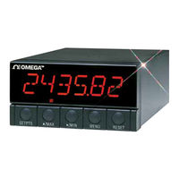
Omega DP461-S User Manual (175 pages)
High Performance Strain Gage Indicator
Brand:
Omega
| Category:
Measuring Instruments
| Size: 1.45 MB
Table of Contents
Table of Contents
3
Section 1 Introduction
11
Description
11
Features
11
Available Models
12
Section 2 Unpacking
14
Section 3 Safety Considerations
16
Safety Considerations
16
Section 4 Parts of the Meter
17
Front of the Meter
17
Figure 4-1 Front Detail
17
Rear of the Meter
20
Figure 4-2A AC Power - Connector Label for Rear Connectors
20
Figure 4-2B DC Power - Connector Label for Rear Connectors
21
Section 5 Setup
23
Conditions Requiring Disassembly
23
Assembly/Disassembly Opening
23
Figure 5-1 Meter Exploded View
24
Figure 5-2 Board Assembly Removing/Installing Detail
25
Safety Precaution/Product ID Label
26
Main Board Power Jumpers
27
Figure 5-3 Transformer Jumpers
27
Printed Circuit Board(S) Installation
28
Figure 5-4 Optional Printed Circuit Board Locations
28
How to Access Jumpers
29
Figure 5-5 Signal Input Board
29
Figure 5-6 Ac-Powered Main Board
30
Figure 5-7 DC-Powered Main Board
30
Figure 5-8 Relay Option Board
31
Figure 5-9 4-Relay Option Board
31
Figure 5-10 Analog Output Option Board
32
Figure 5-11 RS-232 Option Board
32
Figure 5-12 RS-485 Option Board
32
Panel-Mount Assembly
33
Figure 5-13 BCD Option Board
33
Figure 5-14 Panel Mounting Assembly
34
Section 6 Jumper Positions
36
Introduction
36
S1 Jumper Positions for Readrate and Unipolar or Bipolar Input(S)
36
S2 Jumper Positions for Input Range
36
Figure 6-1 S1 and S2 Jumper Locations on Signal Input Board
36
Jumper Setting(S) for Sensor Excitation
38
Jumper Setting(S) for Sensor Excitation Ac-Powered Unit
38
Jumper Setting(S) for Sensor Excitation DC-Powered Unit
40
Section 7 Signal and Power Input Connections
41
Introduction
41
Signal Input Connections
41
Figure 7-1 Current Input Without Sensor Excitation
41
Figure 7-2 Current Input with Sensor Excitation
41
Figure 7-3 Voltage Input Without Sensor Excitation
42
Figure 7-4 3-Wire Voltage Input with Sensor Excitation
42
Connecting Main Power
43
Figure 7-6 Bridge Input with External Sensor Excitation
43
Figure 7-9 AC Connector Wiring at P1
44
Figure 7-10 DC Connector Wiring at P1
44
Section 8 Methods for Scaling the Meter to Display in
45
Figure 8-1 S3 and S4 Main Board Jumper Positions
46
Figure 8-2 S1 and S2 Signal Input Jumper Positions
47
Engineering Units
48
Figure 8-3 Internally-Powered Bridge Input
48
Voltage Input (Non-Ratiometric), Programming the Meter for a Desired Display
59
Figure 8-5 S1 and S2 Signal Input Jumper Positions
60
Figure 8-6 Sensor Input Connections
61
Current Input, Programming the Meter for Adesired Display
72
Figure 8-7 S3 and S4 Main Board Jumper Positions
72
Figure 8-8 S1 and S2 Signal Input Jumper Positions
73
Figure 8-10 S3 and S4 Main Board Jumper Positions
85
Figure 8-11 S1 and S2 Signal Input Jumper Positions
86
Figure 8-12 Sensor Input Connections
86
Section 9 Meter Function Menus
97
Individual Lockout Information
97
Meter Function Menus
98
Input
103
RDG.CNF (Reading Configuration)
103
RDG SC (Reading Scale) and RDG of (Reading Offset)
105
IN CNF (Input Configuration)
107
IN.SC.OF (Input Scale and Offset)
108
DEC PT (Decimal Point)
110
CNT by (Count By)
111
FIL.CNF (Filter Configuration)
112
FIL TI (Filter Time Constant)
113
SP CNF (Setpoints 1 & 2 Configuration)
114
AL CNF (Alarm Configuration)
115
AL FNC (Alarm Function)
117
AL RDG (Alarm Readings)
118
SP DB (Setpoint Deadband)
119
AL DB (Alarm Deadband)
119
OUT.CNF (Output Configuration)
120
OT.SC.OF (Output Scale and Offset)
121
BAUD (Baud Rate)
122
SERCNF (Serial Communication Configuration)
123
ADDRESS (Multipoint Communications Device Address)
124
DAT FT (Data Format)
124
BUS FT (Bus Format)
126
SERCNT (Serial Count)
127
Analog Output Calibration Numbers
128
Section 10 Setpoints/Alarms
129
Features Overview
129
Figure 10-1 Setpoints 1 & 2 Action
130
Figure 10-2 Setpoints 3 & 4 Action
130
Unlocking the Features
131
Selecting "SP CNF" Setpoint Configuration Features
131
Deviation Function for Alarms
132
Figure 10-3 Process Deviation
132
Figure 10-4 High Deviation for both Active above and Active below
132
Selecting "AL CNF" Alarm Configuration Features
133
Figure 10-5 Low Deviation for both Active above and Active below
133
Figure 10-6 Band Deviation for both Active above and Active below
133
Figure 10-7 al CNF Hysteresis
134
AL RDG": Alarm Readings-Select Delay in Alarm Action
136
SP DB": Select "SP 1"And "SP 2" Deadband (Hysteresis)
136
Al Db": Select Alarm 1 ("Sp 3") and Alarm 2 ("Sp 4") Deadband (Hysteresis)
136
OUT.CNF": Control Flashing of the Display
137
Entering Setpoint Levels (in Run Mode)
137
Section 11 Peak and Valley Readings
138
Section 12 Analog Output Option
139
Features Overview
139
Unlocking
140
OUT.CNF": Configuring the Output
140
OT.SC.OF": Setting Output Scale and Offset
140
Board Installation; Entering the Trim Data
141
Figure 12-1 Analog Option Board and Connection Diagram at P5
141
Filter Configuration "FIL.CNF" Value to be Transmitted
143
Wiring/Connections
143
Figure 12-2 Isolated Analog Output Board Wiring Connections
143
Features Overview
144
Figure 13-1 BCD 40-Pin Cable Connector (P8)
144
Figure 13-2 BCD Option Board
145
BCD Card Jumper Table
146
Interconnect Board
146
50-Line Cable Compatibility
147
Selecting the Source of BCD Data: "OUT.CNF
147
Hold Control
147
Data Ready Timing Pulses
147
Bringing out the BCD Overflow Line
147
Digit at a Time Multiplex
147
Digit at a Time Card Address
148
Figure 13-3 Address Programming Chart for 4 -Line Address
148
Select Data Polarity: Jumper S8
149
Decimal Point Address Code
149
Applying Non-Isolated/Isolated Power
149
Driving a Printer
149
Features Overview
150
Figure 14-1 Dual Relay
150
Figure 14-2 4 Relay Board Jumpers and Plugs
151
Wiring/Connections
152
Figure 14-3 Dual Relay Output Board Wiring Connections
152
Figure 14-4 4 Relay Output Board Wiring Connections
152
Features Overview
153
Figure 15-1 RS-232/RS-485 Option Board and Pin Designations
154
Front-Panel Pushbutton Configuration
155
Section 16 External Control Lines
156
Tare (Pin 1)
156
Peak (Pin 2)
156
Valley (Pin 3)
156
Swlin2 (Pin 4)
156
PEAK & VALLEY or EXTERNAL RESET (PIN 5)
156
Push to Cal (Pin 6)
157
Digital Return (PIN 7)
157
Pin 8)
157
Display Hold (PIN 9)
157
LOCKOUT EEPROM (and 'MENU' BUTTON) (PIN 10)
157
Print Command And/Or Reset of Alarms (PIN 11)
157
Nonstandard RX (PIN 12) and Nonstandard TX (PIN 13)
157
Push to Cal (Pin 14)
158
Ext (Pin 15)
158
Sp1 (Pin 16)
158
Sp2 (Pin 17)
158
Al1 (Pin 18)
158
Al2 (Pin 19)
158
Rtn Ext (Pin 20)
158
Error Mode Message
159
Flashing "999999" (Numerical Overflow)
159
Flashing "ERR O1" (Offset Overflow)
159
Flashing "ERR O2" (Setpoint Overflow)
159
NOSTOR" & "STORED (Programming Entries in EEPROM)
159
Flashing "+OVLD" (Positive Input Overload)
159
Flashing "+OPEN" (Open Sensor Indication)
159
Flashing "-OPEN" (Open Sensor Indication)
160
Flashing "I OVSC" (Input Overscale)
160
Flashing "R OVSC" (Reading Overscale)
160
Flashing "CB OVF" (Count by Overflow)
160
Flashing "UOM.OVF" (Unit of Measure Overflow)
160
Troubleshooting Guide
160
Section 18 Specifications
163
Current Input
163
Voltage Input
163
Potentiometer Input
163
General
163
Section 20 Record Your Setup Values
171
Advertisement
Advertisement
Related Products
Omega DP41-B Series
Omega DPF500 Series
Omega DP6060
Omega DPF501
Omega DPF503
Omega DP25B-E
Omega DPF20 Series
Omega PLATINUM DP8EPT
Omega DP3001
Omega DPG8001
Omega Categories
Measuring Instruments
Thermometer
Oven
Watch
Cooktop
More Omega Manuals
Login
Sign In
OR
Sign in with Facebook
Sign in with Google
Upload manual
Upload from disk
Upload from URL