Sign In
Upload
Manuals
Brands
HEIDENHAIN Manuals
Control Panel
ITNC 530 - CYCLE PROGRAMMING
HEIDENHAIN ITNC 530 - CYCLE PROGRAMMING Manuals
Manuals and User Guides for HEIDENHAIN ITNC 530 - CYCLE PROGRAMMING. We have
1
HEIDENHAIN ITNC 530 - CYCLE PROGRAMMING manual available for free PDF download: User Manual
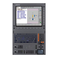
HEIDENHAIN ITNC 530 - CYCLE PROGRAMMING User Manual (514 pages)
Cycle Programming
Brand:
HEIDENHAIN
| Category:
Control Panel
| Size: 10.7 MB
Table of Contents
About this Manual
3
TNC Model, Software and Features
4
Software Options
6
Feature Content Level (Upgrade Functions)
8
New Cycle Functions of Software 340 49X-02
10
Table of Contents
19
Fundamentals / Overviews
21
Fixed Cycles: Drilling
23
Fixed Cycles: Tapping / Thread Milling
24
Fixed Cycles: Pattern Definitions
26
Fixed Cycles: Cylindrical Surface
28
Fixed Cycles: Multipass Milling
30
Cycles: Coordinate Transformations
31
Cycles: Special Functions
33
Touch Probe Cycles: Special Functions
40
Fundamentals / Overviews
43
Available Cycle Groups
45
Overview of Fixed Cycles
45
Overview of Touch Probe Cycles
46
Using Fixed Cycles
47
Machine-Specific Cycles
48
Working with Fixed Cycles
48
Defining a Cycle Using Soft Keys
49
Defining a Cycle Using the GOTO Function
49
Example NC Blocks
49
Calling a Cycle with CYCL CALL
50
Calling a Cycle with CYCL CALL PAT
50
Calling Cycles
50
Calling a Cycle with CYCL CALL POS
51
Calling a Cycle with M99/89
51
Working with the Secondary Axes U/V/W
52
Program Defaults for Cycles
53
Entering GLOBAL DEF
54
Using GLOBAL DEF Information
54
Global Data for Drilling Operations
55
Global Data Valid Everywhere
55
Global Data for Milling Operations with Pocket Cycles 25X
56
Global Data for Positioning Behavior
56
Global Data for Probing Functions
57
Application
58
Pattern Definition PATTERN DEF
58
Entering PATTERN DEF
59
Using PATTERN DEF
59
Defining Individual Machining Positions
60
Defining a Single Row
61
Defining a Single Pattern
62
Defining Individual Frames
63
Defining a Full Circle
64
Defining a Circular Arc
65
Creating a Point Table
66
Function
66
Point Tables
66
Hiding Single Points from the Machining Process
67
Selecting a Point Table in the Program
68
Calling a Cycle in Connection with Point Tables
69
Fixed Cycles: Drilling
71
Basics
72
Overview
72
Centering Diameter or Centering Depth
73
Cycle Parameters
74
Cycle Run
75
Drilling
75
Setup Clearance
76
Reaming
77
Setup Clearance
78
Boring
79
Setup Clearance
82
Universal Drilling
83
Back Boring
87
Setup Clearance
90
Universal Pecking
91
Bore Milling
95
Single-Fluted Deep-Hole Drilling
98
Programming Examples
101
Example: Using Drilling Cycles in Connection with PATTERN DEF
103
Fixed Cycles: Tapping / Thread Milling
105
Tapping New
107
Rigid Tapping
109
Retracting after a Program Interruption
111
Tapping with Chip Breaking
112
Fundamentals of Thread Milling
115
Prerequisites
115
Thread Milling
117
Thread Milling/Countersinking
120
Thread Drilling/Milling
124
Helical Thread Drilling/Milling
128
Outside Thread Milling
132
Fixed Cycles: Pocket Milling / Stud Milling /Slot Milling
139
Rectangular Pocket
141
Circular Pocket
146
Slot Milling
150
Circular Slot
155
Rectangular Stud
160
Circular Stud
164
Fixed Cycles: Pattern Definitions
171
Circular Pattern
173
Linear Pattern
176
Example: Circular Hole Patterns
178
Fixed Cycles: Contour Pocket, Contour Trains
181
Characteristics of the Subprograms
182
SL Cycles
182
Characteristics of the Fixed Cycles
183
Contour Geometry
185
Overlapping Contours
186
Subprograms: Overlapping Pockets
187
Area of Inclusion
188
Area of Exclusion
189
Contour Data
190
Pilot Drilling
192
Rough-Out
194
Floor Finishing
198
Side Finishing
199
Contour Train
201
Trochoidal Slot
205
Finishing with Closed Slots
206
Roughing with Closed Slots
206
Roughing with Open Slots
206
Example: Roughing-Out and Fine-Roughing a Pocket
211
Example: Contour Train
216
Fixed Cycles: Cylindrical Surface
219
Overview of Cylindrical Surface Cycles
220
Cylinder Surface
221
Example: Cylinder Surface with Cycle 27
233
Example: Cylinder Surface with Cycle 28
235
Fixed Cycles: Contour Pocket with Contour Formula
237
SL Cycles with Complex Contour Formula
238
Properties of the Subcontours
239
Selecting a Program with Contour Definitions
240
Defining Contour Descriptions
241
Entering a Complex Contour Formula
242
Contour Machining with Sl Cycles
245
Roughing/Finishing Superimposed Contours with Contour Formula
246
Fixed Cycles: Multipass Milling
253
Run 3-D Data
255
Multipass Milling
257
Ruled Surface
259
Face Milling
263
Example: Multipass Milling
268
Datum Shift
274
DATUM Shift with Datum
275
Editing a Pocket Table in a Program Run Operating Mode
279
Transferring the Actual Values into the Datum Table
279
Configuring the Datum Table
280
To Exit a Datum Table
280
Datum Setting
281
Mirror Image
282
Rotation
284
Scaling Factor
286
Axis-Specific Scaling Factor
288
Working Plane
290
Positioning the Axes of Rotation
293
Automatic Positioning of Rotary Axes
294
Position Display in the Tilted System
295
Positioning in a Tilted Coordinate System
295
Workspace Monitoring
295
Combining Coordinate Transformation Cycles
296
Example: Coordinate Transformation Cycles
299
Cycles: Special Functions
301
Dwell Time
303
Program Call
304
Cycle Function
306
Oriented Spindle Stop
306
Tolerance
307
Influences of the Geometry Definition in the CAM System
308
Cycle Parameters
310
Using Touch Probe Cycles
311
General Information about Touch Probe Cycles
312
Cycles in the Manual and El. Handwheel Modes
313
Touch Probe Cycles for Automatic Operation
313
Before You Start Working with Touch Probe Cycles
315
Maximum Traverse to Touch Point: MP6130
315
Orient the Infrared Touch Probe to the Programmed Probe Direction: Mp
315
Safety Clearance to Touch Point: MP6140
315
Confidence Interval for Multiple Measurement: Mp
316
Consider a Basic Rotation in the Manual Operation Mode: Mp
316
Multiple Measurement: Mp
316
Kinematicsopt, Permissible Deviation of the Calibration Ball Radius: Mp
317
Kinematicsopt: Tolerance Limit in Optimization Mode: Mp
317
Touch Trigger Probe, Probing Feed Rate: MP6120
317
Touch Trigger Probe, Rapid Traverse for Positioning: Mp
317
Executing Touch Probe Cycles
318
Basic Rotation
322
Basic Rotation
331
Compensation Via Rotary Axis
331
Set Basic Rotation
335
Example: Determining a Basic Rotation from Two Holes
340
Touch Probe Cycles: Automatic Datum Setting
341
Measurement Results in Q Parameters
344
Saving the Calculated Datum
344
Slot Center Ref Pt
345
Ridge Center Ref Pt
349
Datum from Outside of Corner
368
Classification of Results
399
Tolerance Monitoring
400
Tool Compensation
400
Tool Monitoring
400
Reference System for Measurement Results
401
Tool Breakage Monitoring
401
Ref. Plane
402
Polar Reference Plane
403
Measure Angle
405
Measure Hole
408
Meas. Circle Outside
412
Meas. Rectan. Outside
420
Measure Inside Width
424
Measure Ridge Width
427
Measure Coordinate
430
Meas. Bolt Hole Circ.
433
Measure Plane
437
Touch Probe Cycles: Special Functions
445
Calibrate Ts
447
Calibrate Ts Length
448
Measuring
449
Cycle Run
451
Measuring in 3-D
451
Cycle Parameters
452
Measure Axis Shift
453
Fast Probing
456
Touch Probe Cycles: Automatic Kinematics Measurement
461
Kinematic Measurement with TS Touch Probes
462
Save Kinematics
464
Log Function
465
Measure Kinematics
466
Positioning Direction
468
Example Calculation of Measuring Positions for an a Axis
469
Machines with Hirth-Coupled Axes
469
Choice of Number of Measuring Points
470
Choice of the Calibration Sphere Position on the Machine Table
470
Notes on the Accuracy
471
Fine Optimization over the Entire Range of Traverse
472
Inspecting the Machine Accuracy
472
Notes on Various Calibration Methods
472
Optimization of a Specific Rotary Axis Position
472
Backlash
473
Position and Angle Optimization Mode Q406 = 2
478
Position Optimization Mode Q406 = 1
478
Test Mode Q406 = 0
478
Various Modes (Q406)
478
Dispersion (Standard Deviation)
480
Error Outputs
480
Evaluation of Measuring Points
480
Notes on Log Data
480
Measurement Uncertainty of Angles
481
Preset Compensation
482
Adjustment of Tool Changer Heads
487
Example: Adjusting a Tool Changer Head
488
Drift Compensation
489
Touch Probe Cycles: Automatic Tool Measurement
493
Setting the Machine Parameters
495
Differences between Cycles 31 to 33 and Cycles 481 to 483
495
Entries in the Tool Table TOOL.T
497
Display of the Measurement Results
498
Calibrating the TT
499
Calibrating the Wireless
500
Measuring the Tool Length
501
Cycle for Measuring a Tool During Rotation
501
Cycle for Measuring a Tool During Standstill (E.g. for Drills)
501
Cycle for Measuring Individual Teeth
501
Measuring the Tool Radius
503
Measuring Tool Length and Radius
505
Fixed Cycles
509
Advertisement
Advertisement
Related Products
HEIDENHAIN ITNC 530 - PILOT SMART NC
HEIDENHAIN iTNC 530 E
HEIDENHAIN ITNC 530 - CONVERSATIONAL PROGRAMMING
HEIDENHAIN iTNC 530 HSCI
HEIDENHAIN IK 5000 QUADRA-CHEK
HEIDENHAIN QUADRA-CHEK IK 529 Series
HEIDENHAIN QUADRA-CHEK IK 539 Series
HEIDENHAIN ID 331143-03
HEIDENHAIN IK 215
HEIDENHAIN ID 510020-61
HEIDENHAIN Categories
Media Converter
Measuring Instruments
Industrial Equipment
Control Systems
Controller
More HEIDENHAIN Manuals
Login
Sign In
OR
Sign in with Facebook
Sign in with Google
Upload manual
Upload from disk
Upload from URL