Sign In
Upload
Manuals
Brands
Enterasys Manuals
Network Hardware
DFE-Platinum 7G4205-72
Enterasys DFE-Platinum 7G4205-72 Manuals
Manuals and User Guides for Enterasys DFE-Platinum 7G4205-72. We have
1
Enterasys DFE-Platinum 7G4205-72 manual available for free PDF download: Hardware Installation Manual
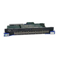
Enterasys DFE-Platinum 7G4205-72 Hardware Installation Manual (96 pages)
DFE-Platinum Series
Brand:
Enterasys
| Category:
Network Hardware
| Size: 2.86 MB
Table of Contents
Industry Canada Notice
4
Product Safety
4
Regulatory Compliance Information
4
Hazardous Substances
5
Declaration of Conformity
8
Safety Information
8
Table of Contents
13
About this Guide
17
Important Notice
17
Who Should Use this Guide
17
How to Use this Guide
18
Related Documents
18
Conventions Used in this Guide
19
Getting Help
20
Chapter 1 : Introduction
21
Overview of DFE-Platinum Series Module Capabilities
21
DFE Module and Interface Options
22
7G4205-72
22
G4285-49
22
7G4285-49 DFE-Platinum Module
23
7G4205-72 DFE-Platinum Module
25
Network Expansion Module (NEM)
26
Connectivity
26
G4285-49
26
Switch Configuration Using Webview
26
Management
26
Switch Configuration Using CLI Commands
27
Secure Networks Policy Support
27
Standards Compatibility
27
LANVIEW Diagnostic Leds
28
Chapter 2: Network Requirements
29
Link Aggregation
30
10BASE-T Network
30
100BASE-TX Network
31
1000BASE-T Network
31
Chapter 3 : Installation
34
Installation Site Requirement
34
Required Tools
34
Unpacking the DFE Module
34
Contents of DFE Module Carton
34
Installing an Optional Network Expansion Module (NEM)
35
DFE Module Placement and Installation Rules
35
Examples, Module Placement in Matrix E7 Chassis
36
Preparing to Install into a Chassis
38
Installing the DFE Modules into a Matrix E7 or N7 Chassis
39
Installing Module into Matrix E7 or N7 Chassis (Matrix E7 Shown)
41
Installing the DFE Modules into a Matrix N3 or N5 Chassis
42
Installing Module into Matrix N3 or N5 Chassis (Matrix N3 Shown)
43
Connecting 48 VDC Power for Poe Operation
44
Connecting to the Network
44
Connecting UTP Cables to DFE Modules
45
Connecting a Twisted Pair Segment with RJ45 Connector
46
Four-Wire Crossover Cable RJ45 Pinouts, Connections between Hub Devices
47
Four-Wire Straight-Through Cable RJ45 Pinouts, Connections between Switches and End User Devices
47
Eight-Wire Crossover Cable RJ45 Pinouts, Connections between Hub Devices
48
Eight-Wire Straight-Through Cable RJ45 Pinouts, Connections between Switches and End User Devices
48
Connecting to COM Port for Local Management
50
What Is Needed
50
Connecting to an IBM PC or Compatible Device
50
Connecting to a VT Series Terminal
51
Connecting an IBM PC or Compatible
51
Connecting to a Modem
52
Connecting a VT Series Terminal
52
Connecting to a Modem
53
Adapter Wiring and Signal Assignments
54
Completing the Installation
56
Completing the Installation of a New System
56
Matrix DFE Startup Screen Example (N7 Chassis)
57
Completing the Installation of a DFE Module in an Existing System
58
Chapter 4: Troubleshooting
59
Using LANVIEW
59
About the Management (MGMT) LED
59
Troubleshooting Checklist
59
Viewing Receive/Transmit Activity on 7G4285-49
60
LANVIEW Leds on 7G4285-49
60
Viewing Receive/Transmit Activity on 7G4205-72
61
LANVIEW Leds on 7G4205-72
61
Viewing the Poe Port Status
62
LANVIEW Leds
63
Troubleshooting Checklist
66
Overview of DFE Module Shutdown Procedure
68
Recommended Shutdown Procedure Using OFFLINE/RESET Switch
69
OFFLINE/RESET Switch
69
Last Resort Shutdown Procedure Using OFFLINE/RESET Switch
70
Appendix A: Specifications
71
DFE Module Specifications
72
7G4285-49 Specifications
72
7G4205-72 Specifications
73
COM Port Pinout Assignments
74
Regulatory Compliance
74
COM Port Pin Assignments
74
Compliance Standards
74
Appendix B: Mode Switch Settings and Option Installations
75
Required Tools
75
Setting the Mode Switches
76
Memory Locations and Replacement Procedures
77
Mode Switch Location (7G4285-49 Shown Without Safety Cover
77
DIMM and DRAM SIMM Locations (7G4285-49 Shown Without Safety Cover
78
Gaining Access to Memory Modules
79
Removing the Safety Cover
79
Removing the Safety Cover
80
DRAM SIMM Replacement Procedure
81
Removing the Optional Network Expansion Module
81
Removing the Existing DIMM
83
DIMM Replacement Procedure
84
Installing the DIMM
84
Removing the Existing DIMM
85
Installing the Network Expansion Module (NEM
86
Installing the DIMM
86
Installing the Network Expansion Module (NEM
87
Reinstalling the Safety Cover
88
Installing the Safety Cover
89
Appendix C: about Poe (Power over Ethernet)
91
Overview
91
Powered Device Classifications
91
C-1 Powered Device Classifications
91
Front Panel 48 VDC Interface
92
Matrix N5 Backplane 48 VDC Interface
92
Power Interface
92
Proprietary PD Detection
92
Poe Port Status Leds
93
Poe Status LED Indications
93
Advertisement
Advertisement
Related Products
Enterasys Matrix DFE-Diamond 7KR4297-02
Enterasys Matrix DFE-Gold 4G4285-49
Enterasys Matrix DFE-Gold 4G4205-72
Enterasys Matrix DFE-Platinum Series
Enterasys Enterasys Matrix DFE-Gold Series
Enterasys Matrix DFE-Diamond Series
Enterasys DFE-Gold 4G4282-49
Enterasys DFE-Gold 4H4202-72
Enterasys DFE-Gold 4H4284-49
Enterasys Matrix DFE-Gold 4H4285-49
Enterasys Categories
Switch
Network Router
Network Hardware
Wireless Access Point
Software
More Enterasys Manuals
Login
Sign In
OR
Sign in with Facebook
Sign in with Google
Upload manual
Upload from disk
Upload from URL