Sign In
Upload
Manuals
Brands
Delta Manuals
Controller
VFD-V Series
Delta VFD-V Series Manuals
Manuals and User Guides for Delta VFD-V Series. We have
1
Delta VFD-V Series manual available for free PDF download: User Manual
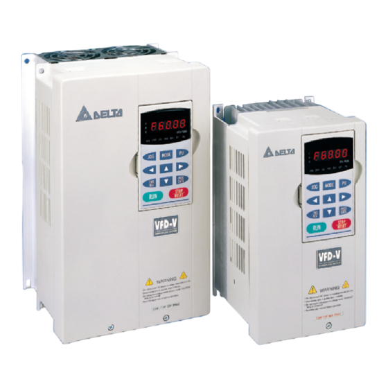
Delta VFD-V Series User Manual (186 pages)
Flux vector control AC motor drivers
Brand:
Delta
| Category:
Controller
| Size: 10.3 MB
Table of Contents
Warning
4
Table of Contents
5
Nameplate Information
8
Model Explanation
8
Chapter 1 Receiving and Inspection
8
Serial Number Explanation
9
Ambient Conditions
10
Chapter 2 Storage and Installation
10
Installation
11
Chapter 3 Wiring
12
Basic Wiring Diagram
13
Wiring of SINK Mode and SOURCE Mode
15
External Wiring
16
Main Circuit Terminal Explanations
17
Control Terminal Explanations
17
Component Explanations
19
Wiring Notice
25
Description of the Digital Keypad VFD-PU05
28
Explanations of Display Messages
28
Chapter 4 Digital Keypad (Vfd-Pu05) Operation
28
Operation Steps of the Digital Keypad VFD-PU05
30
Group 0: System Parameter
32
Chapter 5 Description of Parameter Settings
32
Parameter Reset
33
Definitions of the Multi-Function Display
34
Start-Up Display of the Drive
34
User-Defined Coefficient Setting
35
Frequency and the Operation Method of PU05
36
Control Methods
37
Forward Reverse Transition in V/F Mode
38
Constant Torque Operation Selection
39
Optimal Acceleration/Deceleration Setting
39
Time Unit for Acceleration/Deceleration and S Curve
39
Carrier Frequency Lower Bound
40
Carrier Frequency Upper Bound
40
Center Frequency of Soft Pwm
40
Auto Voltage Regulation (AVR) Function
41
Automatic Energy-Saving Operation
41
Source of the Frequency Command
42
Source of the Operation Command
42
Stop Methods
42
Reverse Operation
43
Group 1: Basic Parameter
44
Maximum Output Frequency
44
Maximum Output Voltage
44
Upper Midpoint Output Voltage
44
Lower Bound Frequency
45
Startup Frequency
45
Upper Bound Frequency
45
Acceleration Time
46
Deceleration Time
46
JOG Acceleration Time
46
JOG Deceleration Time
46
1Th/4Th Acceleration/Deceleration Frequency
47
JOG Frequency
47
S-Curve for Acceleration Arrival Time
48
S-Curve for Acceleration Departure Time
48
S-Curve for Deceleration Arrival Time
48
S-Curve for Deceleration Departure Time
48
Skip Frequency
49
2-Wire/3-Wire Operation Control
50
Group 2: Digital Output/Input Parameter
50
Full List of the Functions
51
Multi-Function Input Command
51
Acceleration/Deceleration Speed of UP/DOWN Key with Constant Speed
54
Digital Input Responding Time
54
UP/DOWN Key Mode
54
Digital Input Operation Direction
55
Multi-Function Output
55
Multi-Function Output Direction
56
Counter Values Achieve the Pre-Set Values
57
Designated Counter Value Achieved
57
Digital Output Gain
58
Pre-Set Arrival Frequency
58
(ACI) Analog Input Bias 2
59
(AUI) Analog Input Bias 3
59
(AVI) Analog Input Bias 1
59
Group 3: Analog Output/Input Parameter
59
(ACI) Positive/Negative Bias Mode
60
(AUI) Positive/Negative Bias Mode
60
(AVI) Positive/Negative Bias Mode
60
Addition Function of the Analog Inputs
61
Analog Input 1 Gain (AVI)
61
Analog Input 2 Gain (ACI)
61
Analog Input 3 Gain (AUI)
61
Analog Input Noise Filter
64
Analog Output Selection
64
Loss of the ACI Signal
64
Analog Output Gain
65
Analog Output Bias Voltage
66
Analog Output Value in REV Direction
66
Multi-Step Speed and Process Control Operation (PCO)
67
The PCO Operation Direction
68
The PCO Time Multiplier
68
Time Duration of the PCO Master Speed
68
Multi-Step Speed Operation Mode
70
Process Control Operation Mode
70
Disable Skip Frequency Width
71
Interfere Jump Width
71
Motor Auto Tuning
72
Motor Parameters
72
Full-Load Current of Motor 1
73
No-Load Current of Motor 1
73
Slip Compensation of Motor 1 (for V/F Mode Only)
73
Torque Compensation of Motor 1 (for the V/F Mode Only)
73
Full-Load Current of Motor 2/No-Load Current of Motor 2
74
Iron Loss of Motor 1
74
LC of Motor 1
74
Number of Poles for Motor 1
74
ASR I (Integration) Time 1
75
Frequency Switch between ASR1 and 2
75
Iron Loss of Motor 2
75
LC of Motor 2
75
Low-Speed Excitation Magnet Compensation
76
R1 Detection Frequency
76
Time Delay of the Pre-Controlled Torque Feedback
76
Vibration Compensation Factor
76
Group 6: Protection Parameter
77
Low Voltage Level
77
Over-Voltage Stall Prevention
77
Over-Current Stall Prevention During Acceleration
78
Phase-Loss Protection
78
Over-Current Deceleration Time During Operation
79
Over-Current Stall Prevention During Operation
79
Over-Torque Detection Level (Ol2)
79
Over-Torque Detection Selection (Ol2)
79
Over-Torque Detection Level 2 (OL3)
80
Over-Torque Detection Selection 2 (OL3)
80
Over-Torque Detection Time (Ol2)
80
Over-Torque Detection Time 2 (OL3)
80
Electronic Thermal Relay Selection
81
Electronic Thermal Relay Time
81
Heat Sink Over-Heat (Oh) Warning
81
Over-Torque Limit
81
Most Recent Fault Record
82
Op Stall Low Limit
82
DC Braking Current Level
84
DC Braking Time at Start-Up/DC Braking Time During a STOP
84
Group 7: Special Parameter
84
Software Braking Level
84
Increasing Rate of the DC Voltage
85
Base Block Time for Speed Search
86
Maximum Allowable Power Loss Time
86
Maximum Current Level for Speed Search
86
Re-Activate after Momentary Power Loss
86
Auto Restart after Fault
87
Deceleration Time for Speed Search
87
Speed Search Frequency (FWD Direction)
88
Speed Search Frequency (REV Direction)
88
Speed Search Type
88
External Terminals RUN after Fault Reset
89
Gear Gap Acceleration-Interruption Frequency
89
Gear Gap Acceleration-Interruption Time
89
Gear Gap Deceleration-Interruption Time/Frequency
89
Group 8: High-Performance Parameter
90
Integral Time (I)/Differential Time (D)
90
Integration’s Upper Bound Frequency
90
PID Feedback Terminal Selection/Proportional Gain (P)
90
One-Time Delay
91
PID Deviation Range
91
PID Frequency Output Command Limit
91
Detection Time of the Feedback Error
92
Dwell (Sleep) Frequency
92
Feedback Signal Fault Treatment
92
Revival Frequency/Dwell (Sleep) Period
92
Fan Control
93
Communication Address
94
Group 9: Communication Parameter
94
Transmission Fault Treatment/Overtime Detection/Communication Protocol
94
Transmission Speed of the Communication
94
Meaning of Encoding
95
WORD Structure
95
Communication Data Structure
96
The Data Format Frame
96
Function Code and Data Contents
98
The CRC Check of the RTU Mode
100
The LRC Check of the ASCII Mode
100
Definition of the Parameters Addresses of the Communication Protocol
101
Additional Response During Erroneous Communication
103
Keypad Transmission Fault Treatment
104
Encoder Input Setting (Channel 1)
105
Group 10: Speed Feedback Parameter
105
PG (Encoder) Pulses
105
PG Feedback Fault Detection Time
106
PG Feedback Fault Treatment
106
PG Feedback Filter Time
106
PG Electrical Gear A/Gear B
107
PG Position Control Point (Home)/Range for PG Position Attained
107
PG Slip Range
107
PG Stall Level (Overspeed Protection)
107
PG Encoder Input Filter Time
108
PG04 Encoder Input Selection (Channel 2)
108
Position Control Parameter
109
Feed Forward
110
Position Control Speed Gain
110
Delay Time for Position Command
111
Direction Command of Absolute P2P
111
PG Position Attained 2
111
Selection of P2P Control Mode
111
REV Limit of Absolute P2P
112
Chapter 6 Maintenance and Inspections
114
Error Message and Troubleshooting
116
Chapter 7 Troubleshooting
116
System Parameter
122
Chapter 8 Parameter Summary
122
Group 1: Basic Parameter
127
Group 2: Digital Output/Input Parameter
129
Group 3: Analog Output/Input Parameter
134
Group 4: Multi-Step Speed and Process Control Operation Parameter
137
Group 5: Motor Parameter
140
Group 6: Protection Parameter
142
Group 7: Special Parameter
145
Group 8: High-Performance Parameter
147
Group 9: Communication Parameter
148
Group 10: Speed Feedback Parameter
149
Specifications
154
Accessories
156
Non-Fuse Circuit Breaker Chart
156
Appendix A Specifications
156
Appendix B Accessories
156
Fuse Specification Chart
156
All Braking Resistors & Braking Units Use in AC Drives
158
Braking Resistors & Braking Units
159
AMD - EMI Filter Cross Reference
162
EMI Filters
163
PG Card
168
Explanations on the PG Card Terminals
169
Exterior of PG-03
170
The Output Types to Accommodate the Encoder
170
VFD-V & VFD-B Series Speed Regulation Comparison
171
Zero Phase Reactor (RF220X00A)
172
Appendix C Dimensions
174
The Apparatus Size of the Digital Hand-Held Programming Panel VFD-PU05
182
Appendix D Ec Declaration of Conformity
184
Advertisement
Advertisement
Related Products
Delta VFD-M-D series
Delta VFD-037B
Delta VFD-370B
Delta VFD-450B
Delta VFD11AMS21AFSHA
Delta VFD11AMS23ANSHA
Delta VFD5A5MS43ANSHA
Delta VFD32AMS43ENSHA
Delta VFD17AMS43ENSHA
Delta VFD7A5MS21ENSHA
Delta Categories
Plumbing Product
Kitchen & Bath Fixtures
Bathroom Fixtures
Saw
Power Supply
More Delta Manuals
Login
Sign In
OR
Sign in with Facebook
Sign in with Google
Upload manual
Upload from disk
Upload from URL