Sign In
Upload
Manuals
Brands
Delta Manuals
Controller
DVP-ES3 Series
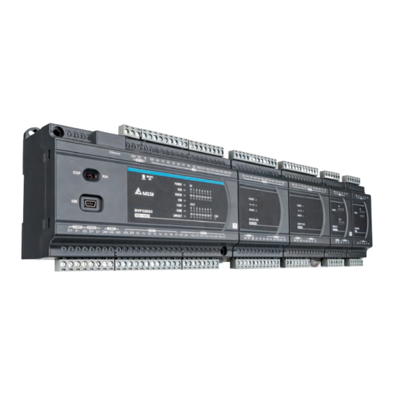
Delta DVP-ES3 Series Manuals
Manuals and User Guides for Delta DVP-ES3 Series. We have
2
Delta DVP-ES3 Series manuals available for free PDF download: Hardware Manual, Operation Manual
Delta DVP-ES3 Series Hardware Manual (489 pages)
Brand:
Delta
| Category:
Industrial Equipment
| Size: 13.72 MB
Table of Contents
Table of Contents
39
CPU Module Specifications
41
DVP-SV3/SX3 Series
56
General Specifications
56
CPU Module Specifications
57
Power Supply Module
66
General Specifications
66
Power Supply Module Profiles
66
Installing and Uninstalling Ispsoft
70
Installing Ispsoft
71
Uninstalling Ispsoft
77
Installing Diadesigner
79
Installing and Uninstalling COMMGR
81
Installing COMMGR
81
Uninstalling COMMGR
84
Notes on Installation
89
Installation
90
Wiring
93
Connecting Power Cables
95
Wiring Digital Input Terminals on CPU Modules
99
Wiring Digital Output Terminals on CPU Modules
103
Wiring Differential Input/Output Module (28EX300MT)
108
Wiring PLC CPU Analog Input /Output Module (EX3 Series)
109
Wiring RS-485 Terminals
110
Wiring Canopen Terminals
110
Recommended USB Wiring for the PLC CPU
111
Recommend Ethernet/Ethercat Wiring for the PLC CPU
111
DVP-SV3/SX3 Series
112
DVP-SV3/SX3 Hardware Framework
112
Notes on Installation
114
Installation
115
Wiring
118
Connecting Power Cables
120
Wiring Digital Input Terminals on DVP-SV3 Series
124
Wiring Digital Output Terminals on DVP-SV3 Series
128
Wiring Digital Input Terminals on DVP-SX3 Series
133
Wiring Digital Output Terminals on DVP-SX3 Series
134
Wiring SX3 Series Analog Input /Output
137
Wiring DVP-SV3/SX3 Communication Ports
138
Basic Structure of I/O Storage
143
Relation between the PLC Action and the Device Type
144
Latched Areas in the Device Range
145
CPU Device Functions
146
Values and Constants
146
Floating-Point Numbers
148
Strings
150
Output Relays (Y)
152
Auxiliary Relays (M)
152
Special Auxiliary Relays (SM)
152
Flags (S)
153
Timers (T)
153
Counters
155
32-Bit Counters (HC)
157
Data Registers (D)
159
Special Data Registers (SR)
159
Index Register (E)
159
File Registers (FR)
160
Quick Start
162
Example
162
Hardware
163
Program
163
Procedure for Creating a Project in Ispsoft
164
Creating a Project
165
Hardware Configuration
166
Configuring a Module
166
Setting the Parameters
167
Creating a Program
168
Adding a Ladder Diagram
168
Basic Editing ─ Creating a Contact and a Coil
170
Basic Editing ─ Inserting a Network and Typing an Instruction
173
Basic Editing ─ Selection of a Network and Operation
176
Basic Editing ─ Connecting a Contact in Parallel
178
Basic Editing ─ Editing a Comment
180
Basic Editing ─ Inserting an Applied Instruction
181
Basic Editing ─ Creating a Comparison Contact and Typing a Constant
183
Writing a Program
184
Checking and Compiling a Program
185
Testing and Debugging a Program
186
Creating a Connection
186
Downloading a Program and Parameters
189
Connection Test
190
Setting a Real-Time Clock
198
Overview of Memory Cards
202
Appearances of Memory Cards
202
Memory Card Specifications
202
Before Using a Memory Card
203
Formatting a Memory Card
203
Installing and Removing a Memory Card
204
Memory Card Slot in a CPU Module
204
Installing a Memory Card
205
Removing a Memory Card
206
Memory Card Contents
207
Initializing a Memory Card
207
Folder Structure in a Memory Card
207
Introduction to the CARD Utility
209
Backing up a Project
211
Restoring a Project
217
CPU Error Log
222
Hardware Configuration Tool for DVP-ES3 Series Modules - Ispsoft HWCONFIG
224
Introduction of the HWCONFIG Environment
224
Configuring a Module
225
Editing a Comment
228
Hardware Configuration Tool for DVP-ES3/EX3/SV3/SX3 Series Modules - Diadesigner
229
Introduction of the Diadesigner Environment
229
Configuring a Module
231
Editing a Comment
232
Setting the Parameters in a DVP-ES3 Series CPU Module - Ispsoft
233
Opening the PLC Parameter Setting Window
233
Setting the Basic CPU Parameters
234
Setting the Parameters in a DVP-ES3/EX3/SV3/SX3 Series CPU Module - Diadesigner
253
Opening the Controller Parameter Setting Window
253
Setting the Basic CPU Parameters
254
Data Exchange
272
Device Settings Dialog Box Descriptions - Ispsoft
272
Device Settings Dialog Box Descriptions - Diadesigner
276
Introduction
285
Ethernet/Ip
285
Definitions of Common Network Terms
286
Ethernet Features
287
Installation
289
Ethernet/Ip Device
289
Network Cable Installation
289
Specifications
293
Ethernet Specification
293
Ethernet/Ip Specification
294
Ethernet Communication Port
295
EIP Builder
296
Run the EIP Builder
296
Set up the IP Address
298
Network
305
Add Devices
308
Data Mapping
311
TAG Function
314
Diagnosis
317
Explicit Message
318
Troubleshooting
319
Ethernet/Ip Error Codes and Their Solutions
319
Studio 5000 Software Operation
322
Architecture
322
Create a New Project
322
Create a Scanner
322
Connect to a Delta Adapter
323
CIP Object
325
Object List
325
Data Type
326
Identity Object (Class ID: 01 Hex)
329
Message Router Object (Class ID: 02 Hex)
331
Connection Manager Object (Class ID: 06 Hex)
334
Port Object (Class ID: F4 Hex)
336
TCP/IP Interface Object (Class ID: F5 Hex)
338
Ethernet Link Object (Class ID: F6 Hex)
341
Register (Class ID: 350 Hex)
344
Y Register (Class ID: 351 Hex)
344
M Register (Class ID: 353 Hex)
346
S Register (Class ID: 354 Hex)
347
C Register (Class ID: 356 Hex)
349
HC Register (Class ID: 357 Hex)
350
SM Register (Class ID: 358 Hex)
351
SR Register (Class ID: 359 Hex)
351
Delta EIP Product List
353
Delta EIP Products
354
Network Security
354
Operation and Monitor on the Web
355
Getting Started
355
Device Information
359
Network Configuration
359
Data Monitoring
362
Diagnostic
367
Configurations
368
Introduction to Canopen
370
Canopen Function Descriptions
370
The Input/Output Mapping Areas
371
Refreshing Mechanism in the Input/Output Mapping Areas
372
Installation and Network Topology
376
Canopen Communication Port
376
Configure the DVP-ES3 Series PLC with HWCONFIG
376
The CAN Interface and Network Topology
378
The Canopen Protocol
383
Introduction to the Canopen Protocol
383
The Canopen Communication Object
384
The Predefined Connection Set
390
Data Structure of SDO Request Message
391
Data Structure of NMT Message
393
Data Structure of EMERGENCY Request Message
395
Example of Sending SDO through the Ladder Diagram
397
Troubleshooting
399
Canopen Network Node State Display
399
Application Example
402
Object Dictionary
411
Introduction
418
Ethercat Port
418
Wiring
419
IP Settings
419
Sm/Sr
419
Ethercat Master
420
Webpage
421
Network Security
422
CPU Module Operations
424
Procedure
424
I/O Refreshing and Communication Service
425
Execution Timing of Interrupts
425
CPU Module Operating Modes
426
Operating Modes
426
Status and Operation under Different Operating Modes
426
Data Tracer
430
About Data Tracer
430
Data Logger
435
About Data Logger
435
Related SM Flags and SR Registors
440
Troubleshooting
443
Basic Troubleshooting Steps
443
Troubleshooting SOP
443
Viewing System Log and Error Step
444
ERROR LED Indicators Are on
447
ERROR LED Indicators Blinking Rapidly Every 0.2 Seconds
449
ERROR LED Indicators Slow Blinking Every 3 Seconds and Lighting up for 1 Second
449
The LED RUN and ERROR Indicators Are Blinking Simultaneously Every
450
Seconds
450
The RUN and LED Indicators Are Blinking One after Another Every
450
Other Errors (Without LED Indicators)
450
Troubleshooting for Other Modules
457
LED Indicators and Error Codes for CPU Modules
457
Disable Driver Signature Enforcement
464
Disable Driver Signature Enforcement in Windows 8
464
Disable Driver Signature Enforcement in Windows 10
466
Installing the USB Driver
468
Notes on Utilizing USB Communication
473
Cautions
484
Daily Maintenance
485
Daily Inspection
485
Periodic Maintenance
486
Periodic Inspection
486
Advertisement
Delta DVP-ES3 Series Operation Manual (411 pages)
Brand:
Delta
| Category:
Controller
| Size: 10.8 MB
Table of Contents
Revision History
3
Table of Contents
3
Chapter 1 Product Introduction
14
Overview
14
Related Manuals
14
Models Descriptions
14
Overview
19
Characteristics
20
2 Chapter 2 Specifications and System
27
General Specifications
28
CPU Module Specifications
29
Functional Specifications
29
Electrical Specifications
30
CPU Module Profiles
32
CPU Module Input/Output Terminals
33
Digital Input/Output Module Specifications
36
General Specifications
36
Digital Input/Output Module Profiles
38
Digital Input/Output Module Terminals
39
Analog Input/Output Module Specifications
42
General Specifications
42
Analog Input/Output Module Profiles
46
Analog Input/Output Terminals
47
Analog Input/Output Module Terminals
47
Temperature Measurement Modules Specifications
48
General Specifications
48
Temperature Measurement Module Profiles
50
Temperature Measurement Module Dimensions
51
Temperature Mesurement Module Terminals
52
Extension Cable Interface Module Specifications
53
General Specifications
53
Extension Cable Interface Module Profiles
53
Installation and Wiring
54
Chapter 3 Installing Software
55
Installing and Uninstalling Ispsoft
56
Installing Ispsoft
57
Uninstalling Ispsoft
61
Installing and Uninstalling COMMGR
63
Installing COMMGR
63
Uninstalling COMMGR
66
4 Chapter 4 Installing Hardware
67
DVP-ES3 Hardware Framework
69
DVP-ES3 Hardware Component
69
Necessary Components
70
Optional Components
70
Installation
71
Linking the CPU Module and a Module
72
Installation on the Set
73
Notes on Installation
71
Wiring
74
Connecting Power Cables
76
Precautions
76
Ground
76
Wiring Power Supply
77
Power Consumption
78
Wiring CPU Modules
80
Wiring Digital Input Terminals
80
Wiring Digital Output Terminals
83
Wiring RS-485 Terminals
87
Wiring Canopen Terminals
87
Wiring Digital Input / Output Modules
88
Wiring DVP08XM211N
88
Wiring DVP08XN211R
88
Wiring DVP08XN211T
89
Wiring DVP08XP211R
89
Wiring DVP08XP211T
90
Wiring DVP16XM211N
91
Wiring DVP16XN211R
92
Wiring DVP16XN211T
93
Wiring DVP16XP211R
94
Wiring DVP16XP211T
95
Wiring DVP24XP200R
96
Wiring DVP24XP200T
97
Wiring DVP24XN200R
98
Wiring DVP24XN200T
98
Wiring DVP32XP200R
99
Wiring DVP32XP200T
100
Wiring Analog Input / Output Modules
101
Wiring DVP06XA-E2
103
Wiring Temperature Measurement Modules
105
Wiring DVP04PT-E2/DVP06PT-E2
105
Wiring DVP04TC-E2
106
Chapter 5 CPU and Module Devices
107
Introduction to CPU Devices
108
Device Table
108
Basic Structure of I/O Storage
109
Relation between the PLC Action and the Device Type
109
Latched Areas in the Device Range
110
CPU Device Functions
111
Values and Constants
111
Floating-Point Numbers
113
Single-Precision Floating-Point Numbers
113
Decimal Floating-Point Numbers
114
Strings
115
Input Relays (X)
116
Output Relays (Y)
117
Auxiliary Relays (M)
117
Special Auxiliary Relays (SM)
117
Flags (S)
118
Timers (T)
118
Counters
120
32-Bit Counters (HC)
122
Data Registers (D)
124
Special Data Registers (SR)
124
Index Register (E)
124
File Registers (FR)
124
Module Device Functions
125
DVP04AD-E2 Control Registers
125
DVP06XA-E2 Control Registers
134
6 Chapter 6 Writing a Program
151
Quick Start
152
Example
152
Hardware
152
Program
153
Procedure for Creating a Project in Ispsoft
153
Creating a Project
154
Hardware Configuration
155
Configuring a Module
155
Setting the Parameters
156
Creating a Program
157
Adding a Ladder Diagram
157
Basic Editing ─ Creating a Contact and a Coil
159
Basic Editing ─ Inserting a Network and Typing an Instruction
162
Basic Editing ─ Selection of a Network and Operation
164
Basic Editing ─ Connecting a Contact in Parallel
167
Basic Editing ─ Editing a Comment
168
Basic Editing ─ Inserting an Applied Instruction
169
Basic Editing ─ Creating a Comparison Contact and Typing a Constant
171
Writing a Program
172
Checking and Compiling a Program
173
Testing and Debugging a Program
174
Creating a Connection
174
Downloading a Program and Parameters
177
Connection Test
178
Setting a Real-Time Clock
186
Chapter 7 Memory Card
187
Overview of Memory Cards
188
Appearances of Memory Cards
188
Memory Card Specifications
188
Before Using a Memory Card
189
Formatting a Memory Card
189
Installing and Removing a Memory Card
189
Memory Card Slot in a CPU Module
189
Installing a Memory Card
190
Removing a Memory Card
190
Memory Card Contents
191
Initializing a Memory Card
191
Folder Structure in a Memory Card
191
Introduction to the CARD Utility
192
Backing up a Project
194
Restoring a Project
199
Restoration Starts Once CPU Is Supplied with Power
203
CPU Error Log
204
Chapter 8 Hardware Configuration and Data Exchange Setups
205
Hardware Configuration Tool for DVP-ES3 Series Modules
206
Introduction of the HWCONFIG Environment
206
Configuring a Module
207
Editing a Comment
207
Setting the Parameters in a DVP-ES3 Series CPU Module
208
Opening the PLC Parameter Setting Window
208
Setting the Basic CPU Parameters
209
Data Exchange
228
Device Settings Dialog Box Descriptions
228
Chapter 9. Ethernet/Ip Specification and Operation
233
Introduction
236
Ethernet/Ip
236
Definitions of Common Network Terms
236
Ethernet Features
237
Delta EIP Architecture
237
EIP Features
238
Installation
238
Ethernet/Ip Device
238
Network Cable Installation
238
Single Port Device
239
Dual Port Device
239
EIP Builder Software
241
Specifications
242
Ethernet Specification
242
Ethernet/Ip Specification
243
Ethernet Communication Port
244
Communication Port Pin Assignment
244
Communication LED Indicator
244
EIP Builder
245
Run the EIP Builder
245
Run the EIP Builder Via an EIP Scanner
245
Set up the IP Address
247
IP Address Types
247
Set the IP Address (Static IP)
247
Set the IP Address (BOOTP/DHCP)
249
Re-Enable BOOTP/DHCP
252
Troubleshooting
254
Error Code Classification
254
Error Codes & How to Fix Them
254
Configuration Errors
254
Application Error
257
Studio 5000 Software Operation
258
Architecture
258
Create a New Project
258
Create a Scanner
260
Create a New Ethernet/Ip Module
260
Connect to a Delta Adapter
262
Import an EDS File
262
Create an Adapter
264
Editing Corresponding Addresses for DVP-ES3
267
Download
268
Data Mapping
269
CIP Object
270
Object List
270
Data Type
271
Identity Object (Class ID: 01 Hex)
274
Message Router Object (Class ID: 02 Hex)
276
Assembly Object (Class ID: 04 Hex)
277
Connection Manager Object (Class ID: 06 Hex)
279
Port Object (Class ID: F4 Hex)
281
TCP/IP Interface Object (Class ID: F5 Hex)
283
Ethernet Link Object (Class ID: F6 Hex)
286
Register (Class ID: 350 Hex)
289
Y Register (Class ID: 351 Hex)
289
D Register (Class ID: 352 Hex)
290
M Register (Class ID: 353 Hex)
291
S Register (Class ID: 354 Hex)
292
T Register (Class ID: 355 Hex)
293
C Register (Class ID: 356 Hex)
294
Chapter 10 Canopen Function and Operation
313
Introduction to Canopen
314
Canopen Function Descriptions
314
The Input/Output Mapping Areas
315
Installation and Network Topology
316
The Dimensions of DVP-ES3 Series PLC
316
Canopen Communication Port
317
Configure the DVP-ES3 Series PLC with HWCONFIG
317
The Canopen Protocol
323
Introduction to the Canopen Protocol
323
The Canopen Communication Object
324
The Predefined Connection Set
329
Data Structure of SDO Request Message
331
Data Structure of EMERGENCY Request Message
335
Example of Sending SDO through the Ladder Diagram
337
Troubleshooting
339
Canopen Network Node State Display
339
Application Example
342
Chapter 11 11 CPU Module Operating Principles
355
CPU Module Operations
356
Procedure
356
I/O Refreshing and Communication Service
357
CPU Module Operating Modes
358
Operating Modes
358
Status and Operation under Different Operating Modes
358
Chapter 12 Troubleshooting
360
Basic Troubleshooting Steps
361
Clear the Error States
361
Troubleshooting SOP
362
System Log
363
ERROR LED Indicators Blinking Rapidly Every 0.2 Seconds
365
ERROR LED Indicators Slow Blinking Every 3 Seconds and Lighting up for 1 Second
365
Other Errors (Without LED Indicators)
365
Seconds
365
The LED RUN and ERROR Indicators Are Blinking Simultaneously Every
365
The RUN and LED Indicators Are Blinking One after Another Every 0.5 Seconds
365
Troubleshooting for Analog Modules (AD/DA/XA) and Temperature Modules (PT/TC)
372
LED Indicators and Error Codes for CPU Modules
373
Chapter 13 Data Tracer and Data Logger
379
Data Tracer
379
About Data Tracer
379
Example
381
Data Logger
382
About Data Logger
382
Related SM Flags and SR Registors
384
Appendix C EMC Standards
401
EMC Standards for an as Series System
401
DVP-ES3 Series System EMC Standards
401
C1.2 Installation Instructions to Meet EMC Standards
403
C1.3 Cables
404
Appendix D Maintenance and Inspection
407
Cautions
407
Daily Maintenance
408
Required Inspection Tools
408
Daily Inspection
408
Periodic Maintenance
410
Required Inspection Tools
410
Periodic Inspection
410
Advertisement
Related Products
Delta DVP-EH3
Delta DVP-ES2
Delta DVP-EX2
Delta DVP-SX2
Delta DVP-20PM
Delta DVP08SN11R
Delta DVP32ES200RC
Delta DVP20SX211S
Delta DVP14SS211R
Delta DVPEN01-SL
Delta Categories
Plumbing Product
Kitchen & Bath Fixtures
Bathroom Fixtures
Saw
Power Supply
More Delta Manuals
Login
Sign In
OR
Sign in with Facebook
Sign in with Google
Upload manual
Upload from disk
Upload from URL