Sign In
Upload
Manuals
Brands
Carrier Manuals
Chiller
Aquasnap 30RAP015
Carrier Aquasnap 30RAP015 Manuals
Manuals and User Guides for Carrier Aquasnap 30RAP015. We have
5
Carrier Aquasnap 30RAP015 manuals available for free PDF download: Start Up & Operation Manual, Operation And Service Manual, Product Data, Installation Instructions Manual
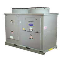
Carrier Aquasnap 30RAP015 Operation And Service Manual (125 pages)
Air-Cooled Chillers with COMFORTLINK Controls
Brand:
Carrier
| Category:
Air Conditioner
| Size: 5.09 MB
Table of Contents
Table of Contents
1
Safety Considerations
2
Unit Sizes
3
Scrolling Marquee Display
3
General
3
Conventions Used in this Manual
3
Basic Controls Usage
3
Accessory Navigator Display Module
4
Scrolling Marquee Display Menu Structure
5
Controls
5
Run Status Mode and Sub-Mode Directory
6
Service Test Mode and Sub-Mode Directory
8
Temperature Mode and Sub-Mode Directory
9
Inputs Mode and Sub-Mode Directory
10
Configuration Mode and Sub-Mode Directory
12
Time Clock Mode and Sub-Mode Directory
16
Operating Mode and Sub-Mode Directory
17
Alarms Mode and Sub-Mode Directory
17
Operating Modes
18
General
19
Main Base Board (MBB)
19
Energy Management Module (EMM)
19
Current Sensor Board (CSB)
19
AUX Board (AUX)
19
Expansion Valve Board (EXV)
19
Enable/Off/Remote Contact Switch
19
Emergency On/Off Switch
19
Board Addresses
19
Control Module Communication
19
Status Inputs
20
Output Relays
20
CCN Communication Bus Wiring
20
Sensors
20
Compressor Return Gas Temperature Sensor
20
Outdoor-Air Temperature Sensor (Oat)
20
Discharge Temperature Thermistor (Dtt)
20
Remote Space Temperature Sensor or Dual
20
Typical Control Box for 30RAP010,015
22
Typical Control Box for 30RAP018-030
22
Typical Wiring Schematic, 30RAP018-030 Units — Power Wiring
24
Main Base Board
28
Enable/Off/Remote Contact Switch/Emergency On/Off Switch Locations
28
Typical Space Temperature Sensor Wiring
28
Energy Management Module
29
Loss-Of-Cooler Flow Protection
29
Minutes Left for Start
29
Minutes off Time
29
Lead/Lag Determination
30
Capacity Control Overrides
30
Deadband Multiplier
31
Electronic Expansion Valves (EXV)
29
Capacity Control
29
Operating Envelope for R-410A Compressor
32
Head Pressure Control
32
Operation of Machine Based on Control Method and Cooling Set Point Selection Settings
32
Fan Stages
33
30RAP Condenser Fan Layout
33
Cooling Set Point Select
33
Low Sound Mode Operation
34
Heating Operation
34
Service Test
34
Optional Factory-Installed Hydronic Package
34
Cooler Pump Control
34
Cooler Pump Sequence of Operation
35
Configuring and Operating Dual Chiller Control
36
Dual Chiller Configuration
37
Dual Leaving Water Thermistor Well
38
Dual Chiller Thermistor Location
38
Temperature Reset
38
Dual Chiller Configuration (Slave Chiller Example)
39
4 To 20 Ma Reset
40
Menu Configuration of 4 to 20 Ma Cooling Set Point Control
40
Configuring Outdoor Air and Space Temperature Reset
41
Configuring Return Temperature Reset
41
DEMAND LIMIT (2-Stage Switch Controlled)
42
Externally Powered Demand Limit
42
Outdoor-Air Temperature Reset
42
Space Temperature Reset
42
Standard Chilled Fluid Temperature Control — no Reset
42
DEMAND LIMIT (CCN Loadshed Controlled)
43
Cooling Set Point (4 to 20 Ma)
43
Configuring Demand Limit
44
Digital Scroll Option
44
Pre-Start-Up
44
Digital Compressor Configuration
44
System Check
44
Sight Glass Location
45
Minimum Cooler Flow Rates and Minimum Loop Volume
45
Start-Up and Operation
45
Actual Start-Up
45
Check Refrigerant Charge
45
Temperature Limits for Standard 30RAP Units
46
Operating Limitations
46
Operation Sequence
46
Service
47
Electronic Components
47
Electronic Expansion Valve (EXV)
47
EXV Troubleshooting Procedure
47
Electronic Expansion Valve Details
48
EXV Cable Connections to EXV Module
49
Unit Torque Specification
49
Compressor Replacement
49
Cooler
49
Oil Charge
50
Microchannel Heat Exchanger (MCHX) Condenser Coil Maintenance and Cleaning
50
Recommendations
50
Compressor Location — 30RAP010-030
51
Compressor Location — 30RAP035-060
51
Check Refrigerant Feed Components
50
Brazed-Plate Cooler Heat Exchanger
50
Thermistor/Temperature Sensor Check
52
Check Unit Safeties
52
Cooler Freeze-Up Protection
52
Thermistors
52
Pressure Transducers
53
Chilled Water Flow Switch
53
Strainer
53
Condenser Fans
53
5K Thermistor Temperatures Vs. Resistance/Voltage Drop
54
Mounted Fan Position
58
Motormaster
58
Controller
58
Drive Programming
59
Replacing Defective Modules
59
Epm Chip
59
Loss of Ccn Communications
59
Wiring Diagram
60
Typical Motormaster Wiring
60
Motormaster V Mode Buttons and Mode Display
60
Fault Codes
61
Motormaster V Program Parameters for Operating Modes
62
Replacement Modules
63
Hydronic Package
63
Recommended Maintenance Schedule
63
Complete Unit Stoppage and Restart
64
Microchannel Heat Exchanger (MCHX) Condenser Coil Maintenance and Cleaning
64
Recommendations
64
Advanced Scroll Temperature Protection Label
65
Alarms and Alerts
65
Recommended Minimum Cool down Time after Compressor Is Stopped
65
Alarm and Alert Codes
67
Compressor Failure Alerts
71
Possible Causes
71
Compressor Stuck on Failure Alarms
72
Display Tables
74
Outputs Mode and Sub-Mode Directory
78
Configuration Mode and Sub-Mode Directory
79
Optional Bacnet Communications Wiring
102
Address Rotary Switches
102
UPC Open Controller
102
SW3 Protocol Switch Settings for MS/TP
103
Baud Selection Table
103
DIP Switches
103
Network Wiring
103
BT485 Terminator Installation
104
MS/TP Wiring Recommendations
104
Open System Wiring Specifications and Recommended Vendors
105
Bacview Device Connection
105
LED Status Indicators
106
Run and Error Leds Controller and Network Status Indication
106
Network Points List
107
Maintenance Summary and Log Sheets
110
30RAP Maintenance Interval Requirements
110
30RAP Monthly Maintenance Log
112
30RAP Seasonal Shutdown Log
113
Troubleshooting
64
Advertisement
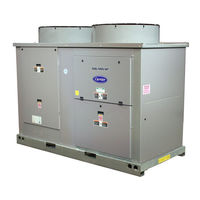
Carrier Aquasnap 30RAP015 Start Up & Operation Manual (132 pages)
Air-Cooled Chillers with ComfortLink Controls
Brand:
Carrier
| Category:
Chiller
| Size: 8.16 MB
Table of Contents
Table of Contents
1
Safety Considerations
2
General
3
Conventions Used in this Manual
3
Basic Controls Usage
3
General
6
Controls
6
Main Base Board (MBB)
22
Energy Management Module (EMM)
23
Current Sensor Board (CSB)
23
AUX Board (AUX)
23
Expansion Valve Board (EXV)
23
Compressor Expansion Board (CXB)
23
Enable/Off/Remote Contact Switch
23
Emergency On/Off Switch
23
Board Addresses
23
Control Module Communication
23
Carrier Comfort Network
24
(CCN) Interface
24
Sensors
25
Cooler Leaving Fluid Sensor
25
Cooler Entering Fluid Sensor
25
Compressor Return Gas
25
Temperature Sensor
25
Outdoor-Air Temperature Sensor (Oat)
25
Discharge Temperature Thermistor (Dtt)
25
Remote Space Temperature Sensor or Dual
25
Leaving Water Temperature Sensor
25
Energy Management Module
26
Loss-Of-Cooler Flow Protection
26
Electronic Expansion Valves (EXV)
26
Capacity Control
26
Minutes Left for Start
27
Minutes off Time
27
Lead/Lag Determination
27
Loading Sequence Select
27
Capacity Control Overrides
27
Head Pressure Control
29
Operation of Machine Based on Control Method and Cooling Set Point Selection Settings
30
Cooling Set Point Select
32
Cooling Set Point (4 to 20 Ma)
32
Low Sound Mode Operation
32
Heating Operation
32
Service Test
32
Optional Factory-Installed Hydronic Package
33
Cooler Pump Control
33
Cooler Pump Operation
33
Cooler Pump Sequence of Operation
33
Configuring and Operating Dual Chiller Control
35
Temperature Reset
35
Demand Limit
41
DEMAND LIMIT (2-Stage Switch Controlled)
41
Externally Powered Demand Limit
41
4 To 20 Ma Controlled
41
DEMAND LIMIT (CCN Loadshed Controlled)
42
Digital Scroll Option
43
Digital Compressor Configuration
43
Pre-Start-Up
43
System Check
43
Start-Up and Operation
43
Actual Start-Up
43
Check Refrigerant Charge
44
Charge Adjustment for Brine Operation
44
Operating Limitations
44
Cooler Flow Rates and Loop Volumes
44
Temperatures
44
Low Ambient Operation
45
Voltage - All Units
45
Operation Sequence
45
Service
46
Electronic Components
46
Electronic Expansion Valve (EXV)
46
EXV Troubleshooting Procedure
46
Exv Valve Replacement
47
Valve Motor Replacement
48
Compressor Replacement
50
Cooler
50
Brazed-Plate Cooler Heat Exchanger
50
Oil Charge
50
Microchannel Heat Exchanger (MCHX) Condenser Coil Maintenance and Cleaning
51
Recommendations
51
Check Refrigerant Feed Components
51
Check Unit Safeties
53
Cooler Freeze-Up Protection
53
Thermistors
53
Pressure Transducers
54
Chilled Water Flow Switch
54
Strainer
59
Condenser Fans
59
Motormaster
59
Controller
59
Drive Programming
60
Epm Chip
60
Loss of Ccn Communications
60
Service
64
Hydronic Package
64
Maintenance
65
Recommended Maintenance Schedule
65
Microchannel Heat Exchanger (MCHX)
65
Recommendations
65
Control Box Maintenance
65
Troubleshooting
65
Complete Unit Stoppage and Restart
65
Unit Enable-Off-Remote Contact Switch Is
65
Chilled Fluid Proof-Of-Flow Switch Open
65
Open 24-V Control Circuit Breakers
65
Motor Overload Protection
66
Alarms and Alerts
67
Alarm/Alert Codes Table
69
Compressor Failure Alerts
74
Compressor Stuck on Failure Alarms
74
Appendix A - Display Tables
77
Appendix B - Ccn Tables
93
Appendix C - Factory Settings for Pump and Manual Starters
106
Option
107
Option
115
Appendix D - Bacnet Communicatons
116
Appendix E - Maintenance Summary and Log Sheets
116
4 To 20 Ma Controlled
119
Index
119
Manufacturer Reserves the Right to Discontinue, or Change at any Time, Specifications or Designs Without Notice and Without Incurring Obligations
120
Start-Up Checklist for 30Rap Liquid Chiller
121
Manufacturer Reserves the Right to Discontinue, or Change at any Time, Specifications or Designs Without Notice and Without Incurring Obligations
132
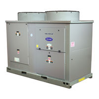
Carrier Aquasnap 30RAP015 Installation Instructions Manual (41 pages)
Liquid Chillers with COMFORTLINK Controls
Brand:
Carrier
| Category:
Chiller
| Size: 3.07 MB
Table of Contents
Table of Contents
1
Installation Instructions
1
Rig and Place the Unit
1
Safety Considerations
1
Dual Pump Units
3
Single Pump Units
3
Standard Units
3
Unit Operating Weights
3
Physical Data, 30RAP — English
4
Physical Data, 30RAP — si
5
Step 1 - Rig and Place the Unit
6
Safety Considerations
6
Cooler Fluid and Drain Piping Connections
6
Installation
6
Step 2 - Check Compressor Mounting
6
Step 3 - Cooler Fluid and Drain Piping
6
All Units
6
Units with Factory-Installed Hydronic Packages
13
System Pressurization
13
Typical Piping Diagram — 30RAP Units with Hydronic Package
13
Typical Dual Pump Package
14
“X” Factor for Setting Tank Pressure
14
Expansion Tank Pre-Charge
14
Air Separation
14
Water Quality Characteristic and Limitations
15
Typical Air Separator
15
Expansion Tank Location on Primary-Secondary Systems
15
Air Separation
15
Unit Rigging Label Detail
6
Step 4 - Fill the Chilled Water Loop
15
Filling the System
16
Maximum Loop Volume (Units with Hydronic Package)
16
Minimum Loop Volume
16
Set Water Flow Rate
16
Head (Ft Water) as Read on Balancing Valve for 30RAP010-030
17
Head (Ft Water) as Read on Balancing Valve for 30RAP035-060
17
Head (Kpa) as Read on Balancing Valve for 30RAP010-030
17
Head (Kpa) as Read on Balancing Valve for 30RAP035-060
17
Heat Exchanger Pressure Drop — 30RAP010-030 (SI)
18
Heat Exchanger Pressure Drop — 30RAP035-060 (English)
18
Heat Exchanger Pressure Drop — 30RAP035-060 (SI)
19
Maximum Loop Volume Limits
19
Minimum Fluid Volume in Circulation
19
Tank Baffling
19
Freeze Protection
20
Power Supply
20
Preparation for Winter Shutdown
20
Preparation for Year-Round Operation
20
Step 5 - Make Electrical Connections
20
Wind Baffle Accessory Quantities
20
30RAP Electrical Data — no Hydronic Package
21
Maximum Field Wiring Sizes
21
Power Supply
21
30RAP Electrical Data
22
Fan Electrical Data
26
Optional Value Sound Fans
26
Standard Low-Sound Aeroacoustic Fans
26
Accessory Tank Electrical Data
27
Pump Electrical Data
27
Compressor Electrical Data
28
Field Connections
29
General Wiring Notes
29
Power Wiring
29
Step 6 - Install Accessories
29
Step 7 - Check Refrigerant Circuit
29
Leak Testing
29
Refrigerant Charge
29
Typical Main Power and Control Connections
30
Non-Fused Disconnect
30
Suction Access Port
31
Unit Pressure Drop Curves, 30RAP010-060
32
Units Without Hydronic Package
32
Pressure Drop Curves, Accessory Storage Tanks
38
Advertisement
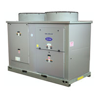
Carrier Aquasnap 30RAP015 Product Data (76 pages)
Air-Cooled Chillers with PURON Refrigerant (R-410A) 10 to 90 Nominal Tons (35 to 316 Nominal kW)
Brand:
Carrier
| Category:
Air Conditioner
| Size: 11.41 MB
Table of Contents
Table of Contents
2
Features/Benefits
2
Model Number Nomenclature
4
AHRI Capacity Ratings
5
Physical Data
6
Options and Accessories
9
Base Unit Dimensions
11
Accessory Dimensions
15
Selection Procedure
18
Performance Data
19
Typical Piping and Wiring
41
Electrical Data
45
Controls
57
Typical Control Wiring Schematic
60
Application Data
61
Guide Specifications
69
Carrier Aquasnap 30RAP015 Product Data (60 pages)
AIr-Cooled Chillers with Puron Refrigerant (R-410A)
Brand:
Carrier
| Category:
Chiller
| Size: 4.23 MB
Table of Contents
Features/Benefits
1
Table of Contents
4
Model Number Nomenclature
4
AHRI Capacity Ratings
5
Physical Data
6
Options and Accessories
9
Base Unit Dimensions
11
Accessory Dimensions
14
Selection Procedure
17
Performance Data
18
Typical Piping and Wiring
31
Electrical Data
34
Controls
43
Typical Control Wiring Schematic
46
Application Data
47
Guide Specifications
54
Advertisement
Related Products
Carrier AQUASNAP 30RAP010-150
Carrier Aquasnap 30RAP010
Carrier Aquasnap 30RAP018
Carrier AquaSnap 30RAP011-060
Carrier Aquasnap 30RAP030
Carrier Aquasnap 30RAP045
Carrier Aquasnap 30RAP050
Carrier Aquasnap 30RAP055
Carrier Aquasnap 30RAP060
Carrier Aquasnap 30RAP040
Carrier Categories
Air Conditioner
Heat Pump
Furnace
Thermostat
Chiller
More Carrier Manuals
Login
Sign In
OR
Sign in with Facebook
Sign in with Google
Upload manual
Upload from disk
Upload from URL