Table of Contents
Advertisement
CONTENTS
SAFETY CONSIDERATIONS . . . . . . . . . . . . . . . . . . . . . . 1
Installation . . . . . . . . . . . . . . . . . . . . . . . . . . . . . . . . 1-31
Step 1 — Rig and Place the Unit. . . . . . . . . . . . . . . . . . 1
• RIGGING
• PLACING UNIT
• MOUNTING UNIT
Step 2 — Check Compressor Mounting . . . . . . . . . . 6
Step 3 — Cooler Fluid and Drain Piping
Connections . . . . . . . . . . . . . . . . . . . . . . . . . . . . . . . . . . . 6
• ALL UNITS
• UNITS WITH FACTORY-INSTALLED
HYDRONIC PACKAGES
• AIR SEPARATION
Step 4 — Fill the Chilled Water Loop . . . . . . . . . . . . 15
• WATER SYSTEM CLEANING
• FILLING THE SYSTEM
• PREPARATION FOR YEAR-ROUND OPERATION
• FREEZE PROTECTION
• PREPARATION FOR WINTER SHUTDOWN
Step 5 — Make Electrical Connections . . . . . . . . . . 20
• POWER SUPPLY
• POWER WIRING
• FIELD CONNECTIONS
Step 6 — Install Accessories . . . . . . . . . . . . . . . . . . . . 29
• ELECTRICAL
Step 7 — Check Refrigerant Circuit . . . . . . . . . . . . . 29
• LEAK TESTING
• DEHYDRATION
• REFRIGERANT CHARGE
APPENDIX A (Pressure Drop Curves) . . . . . . . . 32-38
SAFETY CONSIDERATIONS
Installing, starting up, and servicing air-conditioning equip-
ment can be hazardous due to system pressures, electrical
components, and equipment location (roofs, elevated struc-
tures, etc.).
Only trained, qualified installers and service mechanics
should install, start up, and service this equipment (Fig. 1).
Untrained personnel can perform basic maintenance func-
tions such as cleaning coils. All other operations should be
performed by trained service personnel.
When working on the equipment, observe precautions in the
literature and on tags, stickers, and labels attached to the
equipment.
• Follow all safety codes.
• Wear safety glasses and work gloves.
• Keep quenching cloth and fire extinguisher nearby when
brazing.
• Use care in handling, rigging, and setting bulky
equipment.
These instructions cover installation of 30RAP010-060 air-cooled
liquid chillers. Refer to Fig. 2 for model number to determine factory-
installed options.
Manufacturer reserves the right to discontinue, or change at any time, specifications or designs without notice and without incurring obligations.
Catalog No. 04-53300036-01
Installation Instructions
Page
Printed in U.S.A.
with COMFORTLINK
.
Electrical shock can cause personal injury and death. Shut
off all power to this equipment during installation. There
may be more than one disconnect switch. Tag all discon-
nect locations to alert others not to restore power until work
is completed.
INSTALLATION
Step 1 — Rig and Place the Unit
RIGGING — Preferred method for rigging is with spreader
bars from above the unit. Use hooks in lifting holes. Rig at a
single point with 4 cables or use spreader bars. All panels must
be in place when rigging. See rigging label on unit for details
concerning shipping weights, distance between lifting holes,
center of gravity, and lifting ring dimensions. See Tables 1A
and 1B for physical data. Refer to Fig. 3 for unit weights.
See Fig. 4 for rigging label.
If overhead rigging is not possible, place chiller on skid or
pad for rolling or dragging. When rolling, use a minimum of
3 rollers. When dragging, pull the pad. Do not apply force to
the unit. When in final position, raise from above to lift unit
off pad.
All panels must be in place when rigging. Damage to unit
could result.
PLACING UNIT — There must be at least 3 ft (0.9 m) for
service and for unrestricted airflow on all non-coil sides of unit,
and a minimum of 3.5 ft (1.1 m) clear air space on coil sides.
For multiple units, allow 8 ft (2.48 m) separation between units
for airflow and service.
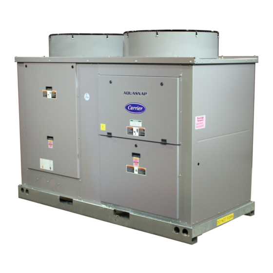
Fig. 1 — Typical 30RAP Unit (018-030 Shown)
Form 30RAP-1SI
Pg 1
AQUASNAP
30RAP010-060
Liquid Chillers
TM
Controls
WARNING
CAUTION
11-09
Replaces: New
®
Advertisement
Table of Contents

Related Manuals for Carrier AQUASNAP 30RAP010-060


Summary of Contents for Carrier AQUASNAP 30RAP010-060
-
Page 1: Installation Instructions
Installation Instructions CONTENTS SAFETY CONSIDERATIONS ..... . 1 INSTALLATION ....... . 1-31 Step 1 —... - Page 2 30RA – Air-Cooled AquaSnap Chiller 30RA Refrigerant Type ® P – Puron Unit Sizes 010 025 045 015 030 050 018 035 055 020 040 060 Voltage 1 – 575-3-60 2 – 380-3-60 5 – 208/230-3-60 6 – 460-3-60 Condenser Coil/Low Sound Options 5 –...
- Page 3 POUNDS 30RAP SIZE POUNDS 30RAP SIZE POUNDS 30RAP SIZE 30RAP010-030 UNITS CONTROL SIDE STANDARD UNITS 30RAP Total SIZE Weight 1125 1133 1242 1283 2163 2185 2238 2263 2369 2375 SINGLE PUMP UNITS 30RAP Total SIZE Weight 1288 1296 1405 1446 2507 2529 2582...
-
Page 4: Physical Data, 30Rap
UNIT 30RAP OPERATING WEIGHT (lb) MCHX Condenser Coil, No Pump MCHX Condenser Coil, Single Pump MCHX Condenser Coil, Dual Pump 1029 REFRIGERANT TYPE Total Refrigerant Charge (lb) Refrigerant Charge (lb) Ckt A/Ckt B 8.6/— COMPRESSORS Quantity Speed (Rpm) (Qty, Tons) Ckt A (1) 11 (Qty, Tons) Ckt B —... - Page 5 UNIT 30RAP OPERATING WEIGHT (kg) MCHX Condenser Coil, No Pump MCHX Condenser Coil, Single Pump MCHX Condenser Coil, Dual Pump REFRIGERANT TYPE Total Refrigerant Charge (kg) Refrigerant Charge (kg) Ckt A/Ckt B 3.9/— COMPRESSORS Quantity Speed (R/s) (Qty, kW) Ckt A (1) 38 (Qty, kW) Ckt B —...
- Page 6 CAUTION Do not circulate water through unit without strainer in place. Failure to use the strainer represents abuse and may impair or otherwise negatively affect the Carrier product warranty. Piping connections are located on the front of the chiller when facing the control panel for sizes 010 to 030 and at the a30-4916 end opposite the control panel for sizes 035 to 060.
- Page 7 a30-4948...
- Page 8 a30-4949...
- Page 9 a30-4950...
- Page 10 a30-4879...
- Page 11 a30-4880...
- Page 12 a30-4881 a30-4880...
- Page 13 UNITS WITH FACTORY-INSTALLED HYDRONIC PACKAGES — The 30RAP chillers with factory-installed hydronic packages are designed for use with closed systems, meaning that there is no more than one water-air interface in the water loop. Cooling tower loops, for example, have two water-air interfaces (sump and nozzles) and would thus be clas- sified as open, whereas a correctly designed chilled water loop with the only water-air interface being in the expansion tank is...
- Page 14 LEGEND — Strainer — Balancing Valve with — Blow-Down Valve — Discharge Check Valve — Field Connections (Dual Pumps Only) — Heater — Service Valves Fig. 12 — Typical Dual Pump Package For example, assuming a system containing a 20% concen- tration of ethylene glycol and 50 feet (15.2 m) in height from the top of the system to the expansion tank, the minimum tank pre-charge pressure would be:...
- Page 15 NPT connection is provided on the valve, allowing hose con- nection for drainage outside the unit. The Carrier ComfortLink™ controls provided have a built- in feature to remind building owners or operators to clean the strainer by discharging the blow-down valve at a pre-set time interval.
- Page 16 3. The gpm corresponding to the pressure drop measured is the flow through the balancing valve. NOTE: Carrier recommends a differential pressure gage when measuring pressures across the pumps or balancing valves. This provides for greater accuracy and reduces error build-up...
- Page 17 Table 4A — Head (Ft Water) as Read on Balancing Valve for 30RAP010-030 SETTING — 16.2 — — Table 4B — Head (kPa) as Read on Balancing Valve for 30RAP010-030 SETTING 13.7 24.2 18.5 41.8 — 12.3 48.4 — — Table 5A —...
- Page 18 Fig. 16B — Heat Exchanger Pressure Drop — 30RAP035-060 (English) Fig. 17A — Heat Exchanger Pressure Drop — 30RAP010-030 (SI) Liters/second 11 & 12 LEGEND 7 — 30RAP035 10 — 30RAP050 8 — 30RAP040 11 — 30RAP055 9 — 30RAP045 12 —...
- Page 19 Fig. 17B — Heat Exchanger Pressure Drop — 30RAP035-060 (SI) Fig. 18 — Tank Baffling Table 6 — Minimum Fluid Volume In Circulation PROCESS COOLING OR NORMAL AIR CONDITIONING 30RAP APPLICATION UNIT APPLICATION gal/ton gal/ton (L per kW) SIZE Std Unit HGBP Digital Std Unit...
- Page 20 VFD. When applied with a VFD, the maximum length of wiring between the drive and the pump motor is 50 ft (15.2 m). The maximum allowable carrier fre- quency of the inverter is 12 kHz, with 3 kHz recommended.
- Page 21 CONNECTION TYPE TERMINAL BLOCK, MCA UP TO 175 AMPS TERMINAL BLOCK, MCA 175 TO 420 AMPS NON-FUSED DISCONNECT, UP TO 100 AMPS NON-FUSED DISCONNECT, 100 TO 200 AMPS NON-FUSED DISCONNECT, 200 TO 450 AMPS AWG — American Wire Gage, kcmil —...
- Page 22 Table 11 — 30RAP Electrical Data — Hydronic Package with Standard Low-Sound AeroAcoustic™ Fan 38RAP UNIT VOLTAGE PUMP OPTIONS "1" OR "8" SIZE V-Hz (3 Ph) 208/230-60 69.4 380-60 35.5 460-60 27.8 575-60 22.1 208/230-60 79.0 380-60 48.4 460-60 38.2 575-60 33.3 208/230-60...
- Page 23 Table 11 — 30RAP Electrical Data — Hydronic Package with Standard Low-Sound 38RAP UNIT VOLTAGE PUMP OPTIONS "4" OR "C" SIZE V-Hz (3 Ph) MOCP 208/230-60 74.7 380-60 61.9 460-60 30.1 575-60 23.9 208/230-60 84.4 380-60 85.1 460-60 40.4 575-60 35.1 208/230-60 95.8...
- Page 24 Table 12 — 30RAP Electrical Data — Hydronic Package with Optional Value Sound Fans PUMP SIZE 1 hp 38RAP UNIT VOLTAGE PUMP OPTIONS "1" OR "8" SIZE V-Hz (3 Ph) MOCP 208/230-60 70.0 380-60 35.5 460-60 28.2 575-60 22.3 208/230-60 79.6 380-60 48.4...
- Page 25 Table 12 — 30RAP Electrical Data — Hydronic Package with Optional Value Sound Fans (cont) 38RAP UNIT VOLTAGE PUMP OPTIONS "4" OR "C" SIZE V-Hz (3 Ph) 208/230-60 75.3 380-60 61.9 460-60 30.5 575-60 24.1 208/230-60 85.0 380-60 85.1 460-60 40.8 575-60 35.3...
- Page 26 Table 13 — Fan Electrical Data — Standard Low-Sound AeroAcoustic™ Fans STANDARD CONDENSER UNIT UNIT VOLTAGE 30RAP V-Hz (3 Ph) 208/230-60 380-60 460-60 575-60 208/230-60 380-60 460-60 575-60 208/230-60 380-60 460-60 575-60 208/230-60 380-60 460-60 575-60 208/230-60 380-60 460-60 575-60 208/230-60 380-60 460-60...
- Page 27 PUMP OPTION PUMP SIZE 1, 8 1.0 HP 2, 9 1.5 HP 3, B 2.0 HP 4, C 3.0 HP 5, 6, D, F 5.0 HP 7, G 7.5 HP LEGEND FLA — Full Load Amps NOTES: 1. Units are suitable for use on electrical systems where voltage sup- plied to the unit terminals is not below or above the listed minimum and maximum limits.
- Page 28 NUMBER OF UNIT COMPRESSORS 30RAP PER CIRCUIT LEGEND LRA — Locked Rotor Amps RLA — Rated Load Amps Table 17 — Compressor Electrical Data UNIT VOLTAGE V-Hz (3 Ph) 208/230-60 380-60 460-60 575-60 208/230-60 380-60 460-60 575-60 208/230-60 380-60 460-60 575-60 208/230-60 380-60...
- Page 29 V installed as standard. Minimum Load Accessory — If minimum load accessory is required, refer to unit Price Pages or contact your local Carrier representative for more details. For installation details, refer to separate installation instructions supplied with the accessory package.
- Page 31 SUCTION ACCESS PORT Fig. 20 — Suction Access Port (Sizes 018-030 Shown)
- Page 32 Unit Pressure Drop Curves, 30RAP010-060 NOTES: 1. Use the following formula to convert feet of water to psig: ft of water (.4335) = psig 2. Use the following formula to convert psig to feet of water: psig (2.306) = ft of water UNITS WITHOUT HYDRONIC PACKAGE (English) APPENDIX A 1 —...
- Page 33 Unit Pressure Drop Curves, 30RAP010-060 NOTES: 1. Use the following formula to convert feet of water to psig: ft of water (.4335) = psig 2. Use the following formula to convert psig to feet of water: psig (2.306) = ft of water UNITS WITHOUT HYDRONIC PACKAGE (SI) APPENDIX A (cont) Liters/Second...
- Page 34 Unit Pressure Drop Curves, 30RAP010-060 NOTES: 1. Use the following formula to convert feet of water to psig: ft of water (.4335) = psig 2. Use the following formula to convert psig to feet of water: psig (2.306) = ft of water UNITS WITH SINGLE PUMP HYDRONIC PACKAGE (English) APPENDIX A (cont) 1 —...
- Page 35 Unit Pressure Drop Curves, 30RAP010-060 NOTES: 1. Use the following formula to convert feet of water to psig: ft of water (.4335) = psig 2. Use the following formula to convert psig to feet of water: psig (2.306) = ft of water UNITS WITH SINGLE PUMP HYDRONIC PACKAGE (SI) APPENDIX A (cont) Liters/second...
- Page 36 Unit Pressure Drop Curves, 30RAP010-060 NOTES: 1. Use the following formula to convert feet of water to psig: ft of water (.4335) = psig 2. Use the following formula to convert psig to feet of water: psig (2.306) = ft of water UNITS WITH DUAL PUMP HYDRONIC PACKAGE (English) APPENDIX A (cont) LEGEND...
- Page 37 Unit Pressure Drop Curves, 30RAP010-060 NOTES: 1. Use the following formula to convert feet of water to psig: ft of water (.4335) = psig 2. Use the following formula to convert psig to feet of water: psig (2.306) = ft of water UNITS WITH DUAL PUMP HYDRONIC PACKAGE (SI) APPENDIX A (cont) Liters/Second...
- Page 38 Pressure Drop Curves, Accessory Storage Tanks 100.0 10.0 100.0 10.0 APPENDIX A (cont) 30RAP035-060 ACCESSORY TANK FLOW RATE (gpm) 30RAP035-060 ACCESSORY TANK FLOW RATE (L/s) 30RAP010-030 1000 30RAP010-030 10.0...
- Page 40 Copyright 2009 Carrier Corporation Manufacturer reserves the right to discontinue, or change at any time, specifications or designs without notice and without incurring obligations. Catalog No. 04-53300036-01 Printed in U.S.A. Form 30RAP-1SI Pg 40 11-09 Replaces: New...