Sign In
Upload
Manuals
Brands
Bosch Manuals
Control Panel
D7212GV4
Bosch D7212GV4 Manuals
Manuals and User Guides for Bosch D7212GV4. We have
2
Bosch D7212GV4 manuals available for free PDF download: Program Entry Manual, Installation And Operation Manual
Bosch D7212GV4 Program Entry Manual (210 pages)
Brand:
Bosch
| Category:
Control Panel
| Size: 3.33 MB
Table of Contents
Table of Contents
3
System Requirements
6
Introduction
7
Using this Program Entry Guide
7
Guide to UL 864 Programming Requirements for D9412GV4 and D7412GV4 Control Panels
7
Guide to UL 636 Programming Requirements for D9412GV4/ D7412GV4/D7212GV4 Control Panels
10
Guide to Programming Descriptions
11
Guide to Keypad Tools
11
Keypad Programming Menu
12
Service Bypass Menu
14
RF Points Menu
14
RF Repeaters Menu
15
RF Diagnostics Menu
15
IP Diagnostics Menu
16
Panel and Area Wide Parameters
17
Phone
17
Phone Parameters
19
Special Point/User Reporting
21
Routing
23
Call Party Disconnect
24
Route Number Groups: Which Has the Highest Priority
24
Programming Primary and Backup Destinations
24
Enhanced Routing
24
Programming a Duplicate Report
25
Routing Destination Communication Failures
25
Message Prioritization Within a Route Number
25
Route Group Parameters
29
Communication Attempts
30
Route Group Categories
33
Programming Path Numbers and Network Addresses for Enhanced Communications
40
Anti-Replay Security Feature
45
SDI Rps/Enhanced Communications Configuration
45
Configuration for RPS over Network
46
Power Supervision
50
Printer Parameters
52
RPS Parameters
54
Uploading and Downloading Reports
54
Log Threshold Reports
54
Panel Initiated Unattended RPS
55
Miscellaneous
59
Area Parameters
61
Shared-Area Characteristics
65
Bell Parameters
66
Open/Close Options
69
Arming Features
74
Keypad (Command Center)
78
Keypad (Command Center) Assignment
79
Area Text
88
Custom Function
89
User Interface
93
Commands
93
Command Authorization
93
Access Control Functions
96
Custom Functions
101
Configuration Authority
101
Authority Level Selections
102
General Functions
108
Report Levels
113
Access Control Levels
114
SIA Duress Passcode Options
116
Function List
116
Relay Parameters
117
Area Relays
118
Panel-Wide Relays
121
Relay/Output Configuration
124
Passcodes, Access Credentials, and User Groups
125
Passcode or Token Worksheet
125
User Credentials
125
Passcodes
125
User Group Window
125
User Name
125
Tokens and Cards
126
Reporting and Logging
126
Points
130
Point Index
130
Point Responses
132
Applications for Point Responses 9, D, and E
132
Characteristics of a Fire Point
133
Point Assignments
146
Cross Point Parameters
149
COMMAND 7 and COMMAND
151
Schedules (Skeds)
154
Windows
154
Opening and Closing
154
User Group Windows
162
Holiday Indexes for User Group Windows
164
Schedules (Skeds)
164
Holiday Indexes
173
Auxparm
174
Automation
174
Miscellaneous
175
SDI2 Modules
179
B208 Octo-Input Module
179
B308 Octo-Output Module
179
B420 Ethernet Communication Module
179
IP Diagnostics Keypad Menu (B420)
189
B820 SDI2 Inovonics Interface Module
190
Wireless Repeater
190
RF Repeaters Keypad Menu (RFID Wireless Repeaters)
191
RF Diagnostics Keypad Menu (RFID Wireless Repeaters)
193
Access Control (D9412Gv4/D7412Gv4)
195
Door Profile
195
Strike Profile
198
Event Profile
200
SIA CP-01 Quick Reference
203
Keypad Tools Menu (Options Not Available in RPS)
204
Service Bypass Menu
204
Setting Service Bypass (PT NUM 1-247)
204
Resetting Service Bypass
204
RF Points Menu
205
Enroll RF Point
205
Replace RF Point
205
Remove RF Point
206
Advertisement
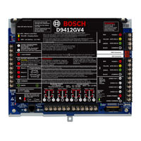
Bosch D7212GV4 Installation And Operation Manual (88 pages)
Brand:
Bosch
| Category:
Control Panel
| Size: 2.96 MB
Table of Contents
Rules
2
Table of Contents
4
Introduction
7
Lightning Strikes
8
Effects
8
Precautions During Installation
8
Overview
9
Configuration and Parts
9
Figure 1: System Configuration
9
Parts List
10
Parts Available by Separate Order
10
Accessories
11
Features in the GV4 Series Control Panels
12
SDI Interconnect Wiring
12
Tip and Ring Posts
12
Telephone Line Sniff
12
Points
12
Areas and Accounts
12
Digital Communicator
12
Keypads
13
Keyswitch
13
Access Control (D9412GV4/D7412GV4)
13
Event Memory
14
Event Log
14
Ground Fault Detection
14
Ground Fault Detection Added Feature
14
Conettix Functions
14
Programming
14
Dual Authentication
14
Other Features
15
Installation
16
Installation Preparation
16
Enclosure Options
16
Mounting Enclosure
16
Figure 2: Enclosure Mounting
16
Installing the Control Panel
17
Connecting Earth Ground
17
Terminal 10
17
Ground Fault Detect Enable
17
Enabling Ground Fault Detection
17
Ground Fault Specifications
17
Figure 3: Enabling Ground Fault Detection
17
Locking the Reset Pin
18
Completing the Installation
18
Charging the Battery
18
Figure 4: Reset Pin
18
Installing and Wiring Detection Devices
19
Installing Modules and Relays
19
Connecting the On-Board Points and Keypads
19
Powering up
19
Updating Control Panel Firmware
19
Programming the Control Panel
19
Installing the Point Chart Label
19
Testing the System
19
Service Walk Test
20
Figure 5: Service Walk Test Flow Chart Example
23
Power Supply
24
Primary Power Terminals 1 and
24
Primary (AC) Power Circuit
24
Installing the Transformer
24
Secondary Power Terminals
24
Installing the Battery
25
Replacing the Battery
27
Battery Charging Circuit
27
Battery Discharge and Recharge Schedule
28
Power Outputs
30
Circuit Protection
30
Total Available Power
30
Continuous Power Output Terminals 3, 8, 24, and
30
Programmable Power Output Terminals 6, 7, and
30
Programming
30
Terminals 6 and
30
Terminal
30
Telephone Connections
32
Registration
32
Notification
32
Location
32
Telephone Cord Connection
32
Phone LED (Red)
33
Operation Monitor LED (Green)
33
Dialing Format
33
Telephone Line Monitor
33
Called Party Disconnect
34
Communication Failure
34
D928 Dual Phone Line Switcher
34
Supervision
42
Figure 14: Connecting the D8125 POPEX to the
42
Figure 15: Connecting the D8125 POPEX to the
43
Figure 16: D8128D Octopopit Layout
47
Figure 17: Connecting D8128D Octopopits to
50
Figure 18: Connecting D8128D Octopopits to
51
Figure 19: Wiring Multiple D8128Ds Using
53
Figure 20: D8128D Octopopit Sensor Loops
54
Figure 21: D8129 Connections to the D9412GV4
57
Figure 22: D8129 Connections to the D7412GV4 or D7212GV4
57
Figure 23: D811 Arm Status Relay Module Wiring to the D9412GV4
61
Figure 24: D811 Arm Status Relay Module Wiring to the D7412GV4 or D7212GV4
61
Description
62
Figure 25: External Power to SDI Devices
64
Figure 26: Keyswitch Wiring
65
Local RPS Programming
67
Figure 27: DX4020 DIP Switch Settings
68
Figure 28: B208 Switches Set to Address 9
69
Figure 29: B308 Switches Set to Address 9
70
Address and Emulation Settings
71
Supervision
71
Figure 30: B420 Switch Set to Address 1
71
Ethernet Communications Module Faults
72
B820 SDI2 Inovonics Interface Module
72
Wireless Receiver Faults
72
Wireless Repeaters Faults
72
Figure 31: B820 Switch Set to Address 1
72
Installer Keypad Tools
73
RPS Access Reports
73
Accessory Connector
74
Figure 32: Accessory Connection on D9412GV4 and D7412GV4
74
GV4 Series Faceplate
75
Figure 33: D9412GV4/D7412GV4/D7212GV4 Faceplate
75
Appendix A: System Wiring Diagrams
76
Power Supply Side System Wiring
76
Figure 34: D9412GV4/D7412GV4/D7212GV4 Power Supply Side System Wiring (Power and Phone)
76
Input Points and Peripheral Devices Wiring Diagrams
77
Figure 35: D9412GV4/D7412GV4/D7212GV4 Input Points and Peripheral Devices System Wiring
77
SDI and Zonex Devices System Wiring
78
Figure 36: D9412GV4 SDI and Zonex Devices
78
Figure 37: D7412GV4/D7212GV4 SDI and Zonex
79
Figure 38: D9412GV4/D7412GV4/D7212GV4 SDI2
80
Appendix B: Point Address Charts
81
Zonex 1 Points
81
Zonex 2 Points
82
SDI2 Points
83
Appendix C: Specifications
84
Control Panel Power Supply
84
Terminal Wiring
85
Advertisement
Related Products
Bosch D7212GV2
Bosch D7212GV3
Bosch D7412GV2
Bosch D7024
Bosch D7412GV3
Bosch DS7200V2-EXP
Bosch D6412
Bosch D4412
Bosch D9412GV2
Bosch DS6R2
Bosch Categories
Dishwasher
Washer
Oven
Power Tool
Dryer
More Bosch Manuals
Login
Sign In
OR
Sign in with Facebook
Sign in with Google
Upload manual
Upload from disk
Upload from URL