Bard W36AB-E Series Manuals
Manuals and User Guides for Bard W36AB-E Series. We have 4 Bard W36AB-E Series manuals available for free PDF download: Literature Assembly, Installation Instructions Manual
Bard W36AB-E Series Literature Assembly (128 pages)
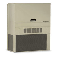
WALL-MOUNT AIR CONDITIONER AND HEAT PUMPS
Table of Contents
Advertisement
Bard W36AB-E Series Installation Instructions Manual (72 pages)
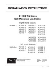
WALL MOUNT AIR CONDITIONER
Brand: Bard
|
Category: Air Conditioner
|
Size: 1.81 MB
Table of Contents
Bard W36AB-E Series Installation Instructions Manual (42 pages)
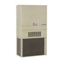
Wall Mount Air Conditioner
Brand: Bard
|
Category: Air Conditioner
|
Size: 1.41 MB
Table of Contents
Advertisement

Bard W36AB-E Series Installation Instructions Manual (42 pages)
Wall Mount Air Conditioner
Brand: Bard
|
Category: Air Conditioner
|
Size: 1.41 MB
Table of Contents
Advertisement