Sign In
Upload
Manuals
Brands
Alvarion Manuals
Network Hardware
BreezeNET PRO.11 Series
Alvarion BreezeNET PRO.11 Series Manuals
Manuals and User Guides for Alvarion BreezeNET PRO.11 Series. We have
2
Alvarion BreezeNET PRO.11 Series manuals available for free PDF download: User Manual, Specifications
Alvarion BreezeNET PRO.11 Series User Manual (209 pages)
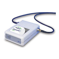
Wireless Networking Product
Brand:
Alvarion
| Category:
Network Hardware
| Size: 7.63 MB
Table of Contents
Table of Contents
5
1 Introduction
13
Scope of the User's Guide
13
Upgrade Procedure
13
Breezenet PRO.11 Series Features
14
Breezenet PRO.11 Series Product Line
15
The Breezenet PRO.11 Access Point
16
Figure 1-1. AP-10 PRO.11 with Two Built-In Omni-Directional Antennas
16
The Breezenet PRO.11 Single Station Adapter
18
Figure 1-2. SA-10 PRO.11 with Two Integrated Omni-Directional Antennas
18
The Breezenet PRO.11 Four Port Station Adapter
19
Figure 1-3. SA-40 PRO.11 with Two Integrated Omni-Directional Antennas
19
The Breezenet PRO.11 Workgroup Bridge
21
Figure 1-4. WB-10D PRO.11 with Two External Antenna Connector Ports
21
The Breezenet PRO.11 SA-PCR Card
23
Figure 1-5. the SA-PCR PRO.11 PC Card
23
The Breezenet PRO.11 Extended Range Access Point and Bridge
24
Breezenet PRO.11 Functional Description
25
Quick Review of Ethernet
25
Startup Procedure
25
Access Point
25
Station Adapter
26
SA-40 Station Adapter
26
Wireless Bridge
26
SA-PCR Station Adapter
27
2 Basic Installation
29
Basic Installation Checklist
29
Check the Packing List
29
Position the Unit
30
Additional Considerations When Positioning the Access Point
31
Connect the Unit to the Power Supply
32
Connect the Unit to the Ethernet Port
32
Check Unit Functionality Via the LED Indicators
33
Station (SA-10, SA-40) and Bridge (WB-10) Leds
33
Access Point Leds
34
Verifying the Ethernet Connection
34
3 Using the Local Terminal for Unit Setup and Management
35
Getting Started with the Local Terminal
35
Configuration Screens
36
Main Menu
39
System Configuration Menu
39
Figure 3-1. Main Menu
39
Figure 3-2. System Configuration Menu
39
Station Status
40
IP and SNMP Parameters
41
Wireless LAN (WLAN) Parameters
41
Bridging
45
Station Control
46
Security (Authentication Feature)
47
Advanced Settings Menu
48
Translation Mode
48
Figure 3-3. Advanced Settings Menu
48
Performance
49
Radio
50
Rate
50
AP Redundancy Support
50
Maintenance
51
Site Survey Menu
51
Figure 3-4. Site Survey Menu
51
System Counters
52
Figure 3-5. Display Rx Packets Per Frequency
57
Survey Software
59
Using the Site Survey Software
59
Figure 3-6. Transmit Statistics
60
Figure 3-7. Receive Statistics
61
Figure 3-8. RSSI to Dbm Graph
61
Display Neighboring Ap's
62
Event Log
62
Access Control Menu
63
Figure 3-9. Access Control Menu
63
4 Sa-Pcr Pro.11 Pc Card Installation, Setup, and Management
65
Packing List
65
Before You Begin
65
Installing the SA-PCR Card
66
Installing the SA-PCR Drivers
67
Figure 4-1. System Properties Window - Windows 95B
69
Figure 4-2. New Hardware Found Window
70
Figure 4-3. SA-PCR LAN Adapter Properties Window
72
Figure 4-4. Windows NT Diagnostics Window
73
Checking the LED Indicators
74
Initial Configuration
75
Installing the SA-PCR Utilities
75
Figure 4-5. Breezecom SA-PCR Utilities Setup
75
Figure 4-6. Breezecom SA-PCR Utilities - Folder Selection Window
76
Figure 4-7. Breezecom SA-PCR Utilities Setup Complete Window
76
Uninstalling SA-PCR Utilities
76
Using the SA-PCR Configuration Utility
77
Figure 4-8. SA-PCR Configuration Utility Main Window - Station Status Tab
77
Station Status Tab
78
Figure 4-9. WLAN Parameters Tab
79
WLAN Parameters Tab
79
Figure 4-10. Station Control Tab
80
Station Control Tab
80
Configuration Access Tab
81
Figure 4-11. Configuration Access Tab
81
Figure 4-12. Power Management Tab
83
Power Management Tab
83
Security Tab
84
Figure 4-13. the Security Tab
85
Figure 4-14. Maintenance Tab
87
Maintenance Tab
87
Figure 4-15. Radio Tab
88
Radio Tab
88
Figure 4-16. Performance Tab
89
Performance Tab
89
Resetting the SA-PCR Card
90
Using the SA-PCR Site Survey Utility
91
Accessing the SA-PCR Site Survey Utility
91
Figure 4-17. SA-PCR Site Survey
91
SA-PCR Site Survey Main Window
92
Figure 4-18. Connection Quality Graph
93
Figure 4-19. Survey Log
93
Performing a Site Survey with the SA-PCR
95
Using the Upgrade Kit Program
96
Figure 4-20. Upgrade Kit Program Introductory Window
96
Figure 4-21. Upgrade Kit Program Welcome Window
97
Figure 4-22. Upgrade Kit Program Step 1
97
Figure 4-23. Upgrade Kit Program Step 2
98
Figure 4-24. Password Dialog Box
98
Figure 4-25. Upgrade Program Step 3
99
Figure 4-26. Upgrade Program Step 4
99
Figure 4-27. Utilities Directory
100
Figure 4-28. Upgrade Program Step 5
100
Installation Troubleshooting
101
Installing the SA-PCR Drivers in ODI Systems
102
5 Planning and Installing Wireless Lans
105
System Configurations
105
Single Cell Configuration
106
Figure 5-1. Point-To-Point Configuration/Connecting Remote Offices to Main Office Network
106
Mobile Applications
107
Figure 5-2. Wireless Bridging between Two or more Wireless LAN Segments
108
Figure 5-3. Single Cell Configuration
109
Overlapping Cell Configuration System Configurations
110
Figure 5-4. Three Overlapping Cells
110
Multicell Configuration
112
Figure 5-5. Multicell Configuration
112
Multi-Hop Configuration (Relay)
113
Figure 5-6. Multi-Hop Configuration
114
Figure 5-7. Advanced Multihop Configuration
114
Indoor Installation Considerations
115
Site Selection Factors
115
Figure 5-8. Breezenet LAN in a Typical Office Environment
115
Antennas for Indoor Applications
117
Construction Materials
118
Cell Size
119
Outdoor Installation Considerations
120
Site Selection Factors
120
Rooftop Installation
121
Antennas for Outdoor Applications
122
Antenna Diversity
123
Antenna Seal
124
Cell Size
124
Link Distance
124
Using Outdoor Range Tables
125
FCC Outdoor Range Tables (USA)
125
ETSI Outdoor Range Tables (Europe/Rest-Of-World) - de Models
128
Non-Regulated Outdoor Range Tables - D Models
129
Extending the Range Using the TPA-24 and LNA-10
131
Planning and Installing Wireless Lans
132
Available Antennas and Antenna Kits
135
Precautions
137
Transmit Antenna
137
Spurious Radio Frequency Emissions
137
Lightning Protection
138
Rain Proofing
138
6 Accessory Installation
139
TPA 24 Transmit Power Amplifier (Booster)
139
Installing the TPA 24
140
Figure 6-1. TPA 24 Installation
140
LNA 10 Low Noise Receive Amplifier
141
Installing the LNA 10
141
RFS 122 Radio Frequency Splitter
142
Figure 6-2. LNA 10 Connections Diagram
142
Installing the RFS 122
143
AL 1 Lightning Arrestor
143
Figure 6-3. RFS-122 Connection Diagram
143
AMP 2440 Bi-Directional Amplifier
144
Figure 6-4. AL-1 Connection Block Diagram
144
Figure 6-5. AMP 2440 Functional Block Diagram
144
Figure 6-6. AMP 2440 Installation and Mounting
146
Installing the AMP 2440 Bi-Directional Amplifier
146
Figure 6-7. AMP 2440 Installation Details
147
7 Upgrade Procedure
149
8 System Troubleshooting
151
Troubleshooting Guide
151
Checking Counters
155
WLAN Counters
155
Ethernet Counters
155
9 Appendix
157
Supported Mibs and Traps
157
Supported Mibs
157
Supported Traps
158
Technical Specifications
159
Specifications for Breezenet PRO.11 Units
159
Specifications for TPA 24 Transmit Power Amplifier
162
Specifications for LNA 10 Low Noise Receive Amplifier
163
Specifications for RFS 122 Radio Frequency Splitter
164
Specifications for al 1 Lightning Arrestor
164
Specifications for AMP 2440 Bi-Directional Power Amplifier
165
Wireless LAN Concepts
166
Figure 9-1. Wired LAN Topology
167
Figure 9-2. the Basic Wireless LAN Cell
168
Figure 9-3. Wireless LAN Connectivity
169
Figure 9-4. Roaming through Overlapping Cells
170
Figure 9-5. the Common Coverage Area of a Multi-Cell Structure
171
Radio Signal Propagation
173
Introduction
173
Figure 9-6. Typical Radio System
173
RF Terms and Definitions
174
Figure 9-7. Attenuation of an RF Signal
174
Figure 9-8. Side View
176
Figure 9-9. Top View
176
Figure 9-10. Radiation Pattern of Directional Antenna
177
Figure 9-11. Multipath Reception
179
Figure 9-12. Fresnel Zone
180
IEEE 802.11 Technical Tutorial
181
Architecture Components
181
Figure 9-13. Fresnel Zone Clear of Obstacles
181
Figure 9-14. Typical 802.11 LAN
182
IEEE 802.11 Layers Description
183
The MAC Layer
183
Figure 9-15. Transaction between Stations a and B
186
Figure 9-16. Frame Fragmentation
187
How Does a Station Join an Existing Cell
189
Figure 9-17. Access Mechanism
189
Roaming
190
Keeping Synchronization
191
Security
191
Power Saving
192
Frame Types
193
Frame Formats
194
Figure 9-18. MAC Frame Format
195
Figure 9-19. Frame Control Field
195
Power Management
197
Most Common Frame Formats
199
Figure 9-20. RTS Frame Format
199
Figure 9-21. CTS Frame
200
Figure 9-22. ACK Frame Format
200
Point Coordination Function (PCF)
201
Ad-Hoc Networks
201
Advertisement
Alvarion BreezeNET PRO.11 Series Specifications (2 pages)
Wireless LAN
Brand:
Alvarion
| Category:
Network Hardware
| Size: 0.13 MB
Advertisement
Related Products
Alvarion BreezeMAX PRO 5000 CPE
Alvarion BreezeACCESS SU-M
Alvarion BreezeACCESS SU-M-900
Alvarion BreezeACCESS VL
Alvarion BreezeNET B
Alvarion Categories
Network Hardware
Wireless Access Point
Software
Modem
Power Supply
More Alvarion Manuals
Login
Sign In
OR
Sign in with Facebook
Sign in with Google
Upload manual
Upload from disk
Upload from URL