Alcatel-Lucent 7210 SAS-D Manuals
Manuals and User Guides for Alcatel-Lucent 7210 SAS-D. We have 2 Alcatel-Lucent 7210 SAS-D manuals available for free PDF download: Configuration Manual, Installation Manual

Alcatel-Lucent 7210 SAS-D Configuration Manual (462 pages)
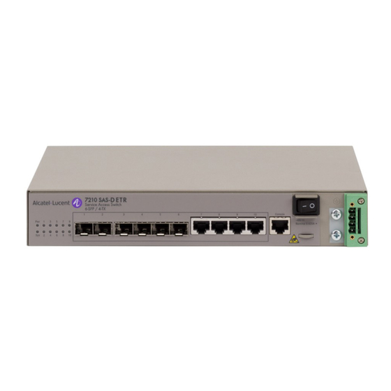
Service Access Switch
Brand: Alcatel-Lucent
|
Category: Switch
|
Size: 2.42 MB
Table of Contents
Advertisement

Alcatel-Lucent 7210 SAS-D Installation Manual (88 pages)
Service Access Switch
Brand: Alcatel-Lucent
|
Category: Switch
|
Size: 0.94 MB