Sign In
Upload
Manuals
Brands
Alcatel-Lucent Manuals
Switch
7210
Alcatel-Lucent 7210 Manuals
Manuals and User Guides for Alcatel-Lucent 7210. We have
3
Alcatel-Lucent 7210 manuals available for free PDF download: Installation Manual
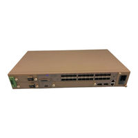
Alcatel-Lucent 7210 Installation Manual (90 pages)
SERVICE ACCESS SWITCH (SAS) ETHERNET
Brand:
Alcatel-Lucent
| Category:
Switch
| Size: 0.7 MB
Table of Contents
Table of Contents
3
Ist of
5
Preface
9
Preface
10
Table 1: Information Symbols
10
7210 SAS-E Overview
11
Switch Features
12
Figure 1: 7210 SAS-E Front Panel
12
Switch Architecture
13
Network Management Options
13
7210 SAS-E Overview
13
Features
14
Connectivity
14
Hardware Description
15
7210 SAS-E Overview
15
Table 2: 7210 SAS-E Front Panel Features
15
Figure 2: 7210 SAS E Front Panel
15
Ethernet Interfaces
16
Console Port
16
Management Port
16
Alarm Interface Port
17
Table 3: Alarm Interface Port Pinouts
17
Table 17: Alarm Interface Port Pinouts
18
Figure 3: AC and DC Power Modules
19
Power Modules
19
Table 4: Power Module Leds
19
DC Power Source Failure Detection
21
Table 5: Power Source Failure Detection Capability
22
Fan Tray
24
Figure 4: Fan Tray
24
USB Port
24
Figure 5: Removing and Replacing the Fan Tray and Air Filter
25
Figure 6: System Leds and Buttons
26
System Leds and Buttons
26
Table 6: 7210 SAS-E System Leds and Buttons
26
Port Leds
27
System and Port Leds
27
Table 7: System and Port Status Leds
27
Table 8: 100/1000 Fiber-Optic SFP and 10/100/1000Base-T Copper Port Leds
27
Figure 7: SFP Port Leds
28
System Buttons and Switches
28
Table 10: Front Panel Buttons and Switches
28
Table 9: Port LED Key Descriptions
28
Installing the 7210 SAS-E
31
Site Preparation
32
Selecting a Site
32
Ethernet Cabling
32
Equipment Checklist
33
Installing the 7210 SAS-E
33
Installing Your Switch
34
Rack Mounting
34
Figure 8: Attaching the Brackets
34
Installing the 7210 SAS-E
35
Figure 9: Installing the Switch in a Rack
35
Desktop or Shelf Mounting
36
Figure 10: Attaching the Adhesive Feet
36
Grounding the Chassis
37
Connecting to a Power Source
38
Connecting to AC Power
38
Connecting to DC Power
39
Figure 11: Connecting to a -48 VDC Power Source
40
Figure 12: Connecting to a +24 VDC Power Source
40
Connecting to the Console Port
41
Table 11: Serial Cable Wiring
41
Warnings and Notes
44
Installation Preparation
45
Locking Mechanisms
45
Installing Sfps
46
Removing Sfps
46
Configuring the 7210 SAS-E
47
Diagnostics
48
Post Installation Status
48
Initializing the System and Downloading Software
49
Booting a 7210 SAS-E in the Lab
49
Configuring the 7210 SAS-E
49
Figure 13: 7210 SAS-E Boot Process
49
Booting a 7210 SAS-E Using the Image on Flash (with the Image Shipped by Factory)
50
Booting a 7210 SAS-E from the Network
53
Default Settings
54
Using the Out-Of-Band Ethernet Management Port to Boot 7210 from the Nework
60
Configuring the 7210 SAS-E
61
Downloading the Timos Software to the Internal Flash
62
Establishing Router Connections
66
Console Connection
66
Table 12: Console Configuration Parameter Values
66
Telnet Connection
67
Running Telnet
68
Restarting the Router
69
Troubleshooting
71
Troubleshooting
72
Diagnosing Switch Indicators
72
Table 13: Troubleshooting
72
Power and Cooling Problems
73
Installation
74
In-Band Access
75
Troubleshooting
77
Appendix A: Specifications
77
Appendix A: Specifications
78
Specifications
78
Table 14: 7210 SAS-E Specifications
78
Japan VCCI Class a Declaration
79
Rohs and WEEE
79
Appendix B: Pin Assignments
81
Appendix B: Pin Assignments
82
Management Port Pin Assignments
82
Table 15: 10/100BASE-TX MDI and MDI-X Port Pinouts
82
Console Port Pin Assignment
83
Table 16: Serial Cable Wiring
83
Appendix B: Pin Assignments
83
Appendix C: Alarm Pin Assignments
85
Alarm Port Pin Assignments
86
Figure 14: DB-15 Alarm Connector
86
Appendix C: Alarm Pin Assignments
87
Figure 15: Alarm Input Connection Diagram
88
Advertisement
Alcatel-Lucent 7210 Installation Manual (88 pages)
SERVICE ACCESS SWITCH (SAS) MPLS
Brand:
Alcatel-Lucent
| Category:
Switch
| Size: 0.81 MB
Table of Contents
Table of Contents
3
Ist of
5
Preface
9
Preface
10
Table 1: Information Symbols
10
7210 SAS-M Overview
11
7210 SAS-M Introduction and Features
12
Figure 1: 7210 SAS-M 24F Front Panel
12
7210 SAS-M Overview
13
Figure 2: 7210 SAS-M 24F 2XFP and 7210 SAS-M 24F 2XFP ETR Front Panel
13
Switch Architecture
14
Network Management Options
14
Features
15
Connectivity
15
Hardware Description
16
Figure 3: 7210 SAS-M 24F Front Panel
16
Table 2: 7210 SAS-M Front Panel Features
16
Figure 4: 7210 SAS-M 24F XFP and 7210 SAS-M 24F XFP ETR Front Panel
17
Table 3: 7210 SAS-M 24F Xfpand 7210 SAS-M 24F XFP ETR Front Panel Features
17
Ethernet Interfaces
18
Management Port
18
Console Port
19
Alarm Interface Port
20
Table 4: Alarm Interface Port Pinouts
20
7210 SAS-M Overview
21
Table 18: Alarm Interface Port Pinouts
21
Power Modules
22
Figure 5: AC and DC Power Modules
22
Table 5: Power Module Leds
22
DC Power Source Failure Detection
24
Table 6: Power Source Failure Detection Capability
25
Fan Tray
27
Figure 6: Fan Tray
27
USB Port
27
Figure 7: Removing and Replacing the Fan Tray and Air Filter
28
Figure 8: System Leds and Buttons
29
System Leds and Buttons
29
Table 7: 7210 SAS-M System Leds and Buttons
29
Port Leds
30
System and Port Leds
30
Table 8: System and Port Status Leds
30
Table 9: Port Leds
30
Figure 9: SFP Port Leds
31
Table 10: Port LED Key Descriptions
31
System Buttons and Switches
32
Table 11: Front Panel Buttons and Switches
32
Installing the 7210 SAS-M
33
Site Preparation
34
Selecting a Site
34
Ethernet Cabling
34
Equipment Checklist
35
Installing the 7210 SAS-M
35
Installing Your Switch
36
Rack Mounting
36
Figure 10: Attaching the Brackets
36
Installing the 7210 SAS-M
37
Figure 11: Installing the Switch in a Rack
37
Desktop or Shelf Mounting
38
Figure 12: Attaching the Adhesive Feet
38
Grounding the Chassis
39
Connecting to a Power Source
41
Connecting to AC Power
41
Connecting to DC Power
42
Figure 13: Connecting to a -48 VDC Power Source
43
Figure 14: Connecting to a +24 VDC Power Source
43
Connecting to the Console Port
44
Table 12: Serial Cable Wiring
44
In this Chapter
45
Warnings and Notes
46
Installation Preparation
47
Locking Mechanisms
47
Installing Sfp/Xfps
48
Removing Sfp/Xfps
48
Configuring the 7210 SAS-M
49
Diagnostics
50
Post Installation Status
50
Initializing the System and Downloading Software
51
Booting a 7210 SAS-M in the Lab
51
Configuring the 7210 SAS-M
51
Figure 15: 7210 SAS-M Boot Process
51
Booting a 7210 SAS-M Using the Image on Flash (with the Image Shipped by Factory)
52
Booting a 7210 SAS-M from the Network
54
Using the Out-Of-Band Ethernet Management Port to Boot 7210 from the Nework
60
Configuring the 7210 SAS-M
61
Downloading the Timos Software to the Internal Flash
63
Establishing Router Connections
65
Console Connection
65
Table 13: Console Configuration Parameter Values
65
Telnet Connection
66
Running Telnet
67
Troubleshooting
69
Troubleshooting
70
Diagnosing Switch Indicators
70
Table 14: Troubleshooting
70
Power and Cooling Problems
71
Installation
72
In-Band Access
73
Troubleshooting
75
Appendix A: Specifications
75
Appendix A: Specifications
76
Specifications
76
Table 15: 7210 SAS-M Specifications
76
Japan VCCI Class a Declaration
77
Rohs and WEEE
77
Appendix B: Pin Assignments
79
Appendix B: Pin Assignments
80
Management Port Pin Assignments
80
Table 16: 10/100BASE-TX MDI and MDI-X Port Pinouts
80
Console Port Pin Assignment
81
Table 17: Serial Cable Wiring
81
Appendix B: Pin Assignments
81
Appendix C: Alarm Pin Assignments
83
Alarm Port Pin Assignments
84
Figure 16: DB-15 Alarm Connector
84
Appendix C: Alarm Pin Assignments
85
Figure 17: Alarm Input Connection Diagram
86
Alcatel-Lucent 7210 Installation Manual (72 pages)
Service Access Switch (SAS-X)
Brand:
Alcatel-Lucent
| Category:
Switch
| Size: 0.67 MB
Table of Contents
Table of Contents
3
Preface
9
Preface
10
Table 1: Information Symbols
10
7210 SAS-X Overview
11
7210 SAS-X Introduction and Features
12
Figure 1: 7210 SAS-X Front Panel
12
Switch Architecture
13
Network Management Options
13
7210 SAS-X Overview
13
Features
14
Connectivity
14
Hardware Description
15
7210 SAS-X Overview
15
Table 2: 7210 SAS-X Front Panel Features
15
Figure 2: 7210 SAS-X Front Panel
15
Ethernet Interfaces
16
Management Port
16
Console Port
17
Alarm Interface Port
18
Table 3: Alarm Interface Port Pinouts
18
Power Modules
20
Table 4: Power Module Leds
20
Figure 3: AC and DC Power Modules
20
USB Port
22
Fan Tray
22
Figure 4: Fan Tray
22
Figure 5: Removing and Replacing the Fan Tray and Air Filter
23
System Leds and Buttons
24
Table 5: 7210 SAS-X System Leds and Buttons
24
Figure 6: System Leds and Buttons
24
System and Port Leds
25
Port Leds
25
Table 6: System and Port Status Leds
25
Table 7: Port Leds
25
Table 8: Port LED Key Descriptions
26
Figure 7: SFP Port Leds
26
System Buttons and Switches
27
Table 9: Front Panel Buttons and Switches
27
Installing the 7210 SAS-X
29
Site Preparation
30
Selecting a Site
30
Ethernet Cabling
30
Equipment Checklist
31
Installing the 7210 SAS-X
31
Installing Your Switch
32
Rack Mounting
32
Figure 8: Attaching the Brackets
32
Installing the 7210 SAS-X
33
Figure 9: Installing the Switch in a Rack
33
Desktop or Shelf Mounting
34
Figure 10: Attaching the Adhesive Feet
34
Grounding the Chassis
35
Connecting to a Power Source
36
Connecting to AC Power
36
Connecting to DC Power
37
Connecting to the Console Port
38
Table 10: Serial Cable Wiring
38
In this Chapter
39
Warnings and Notes
40
Installation Preparation
41
Locking Mechanisms
41
Installing Sfp/Xfps
42
Removing Sfp/Xfps
42
Configuring the 7210 SAS-X
43
Diagnostics
44
Post Installation Status
44
Initializing the System and Downloading Software
45
Booting a 7210 SAS-X in the Lab
45
Configuring the 7210 SAS-X
45
Figure 11: 7210 SAS-X Boot Process
45
Booting a 7210 SAS-X from the Network
46
Configuring the 7210 SAS-X
47
Using the Out-Of-Band Ethernet Management Port to Boot 7210 from the Network
51
Downloading the Timos Software to the Internal Flash
54
Establishing Router Connections
56
Console Connection
56
Table 11: Console Configuration Parameter Values
56
Telnet Connection
57
Running Telnet
58
Troubleshooting
59
Troubleshooting
60
Diagnosing Switch Indicators
60
Table 12: Troubleshooting
60
Power and Cooling Problems
62
Installation
63
In-Band Access
64
Appendix A: Specifications
65
Appendix A: Specifications
66
Specifications
66
Table 13: 7210 SAS-X Specifications
66
Japan VCCI Class a Declaration
67
Rohs and WEEE
67
Appendix B: Pin Assignments
69
Management Port Pin Assignments
70
Table 14: 10/100BASE-TX MDI and MDI-X Port Pinouts
70
Console Port Pin Assignment
71
Appendix B: Pin Assignments
71
Table 15: Serial Cable Wiring
71
Advertisement
Advertisement
Related Products
Alcatel-Lucent 7210 SAS-D
Alcatel-Lucent 7210 SAS-T
Alcatel-Lucent 7210 SAS-X
Alcatel-Lucent 7210 SAS-R6 OS
Alcatel-Lucent 7210 SAS R12
Alcatel-Lucent 7210 SAS-E
Alcatel-Lucent 7210 SAS-K
Alcatel-Lucent 7210 SAS D
Alcatel-Lucent 7210 Sas-R6
Alcatel-Lucent 7210 SAS Series
Alcatel-Lucent Categories
Switch
Telephone
Network Router
IP Phone
Network Hardware
More Alcatel-Lucent Manuals
Login
Sign In
OR
Sign in with Facebook
Sign in with Google
Upload manual
Upload from disk
Upload from URL