Sign In
Upload
Manuals
Brands
Agilent Technologies Manuals
Switch
Agilent 34980A
Agilent Technologies Agilent 34980A Manuals
Manuals and User Guides for Agilent Technologies Agilent 34980A. We have
7
Agilent Technologies Agilent 34980A manuals available for free PDF download: User Manual, Service Manual, Getting Started Manual, Application Note, Brochure
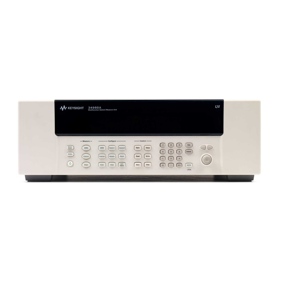
Agilent Technologies Agilent 34980A User Manual (349 pages)
Multifunction Switch/Measure Unit
Brand:
Agilent Technologies
| Category:
Switch
| Size: 6.04 MB
Table of Contents
Safety Notices
3
Table of Contents
7
Introduction to the 34980A
14
Front Panel at a Glance
14
Rear Panel at a Glance
15
Rear Panel Connector Pinouts
16
External Trigger/Alarms Connector (Male D-Sub)
16
Analog Bus Connector (Female D-Sub)
16
Annunciator Display Indicators
17
Front Panel Menu Reference
18
Instrument Rack Mounting
19
Features and Functions
21
Clearing 34980A Memory
22
SCPI Language Conventions
23
Rules for Using a Channel List
23
General Measurement Configuration
25
Overview of Measurement Modes
25
Analog Buses
28
Measurement Functions
29
Measurement Range
30
Measurement Resolution
31
Custom A/D Integration Time
32
Autozero
34
Trigger Delay
35
Automatic Trigger Delays
36
Safety Interlock
37
User-Defined Channel Labels
38
2-Wire Versus 1-Wire Mode
40
Analog Bus and Internal DMM Considerations
41
Environmental Operating Conditions
41
Electrical Operating Conditions
42
Temperature Measurement Configuration
43
Measurement Units
43
Thermocouple Measurements
44
RTD Measurements
46
Thermistor Measurements
47
Voltage Measurement Configuration
48
DC Input Resistance
48
AC Low Frequency Filter
49
Resistance Measurement Configuration
50
Offset Compensation
50
Current Measurement Configuration
51
AC Low Frequency Filter
51
Frequency Measurement Configuration
52
Low Frequency Timeout
52
MX+B Scaling
53
Scanning
55
Rules for Scanning
55
Adding Channels to the Scan List
57
Scan Trigger Source
59
Trigger Count
64
Sweep Count
65
Sample Count
66
Channel Delay
68
Automatic Channel Delays
69
Reading Format
71
Non-Sequential Scanning
72
Viewing Readings Stored in Memory
73
Monitor Mode
75
Scanning with External Instruments
77
Alarm Limits
80
Viewing Stored Alarm Data
84
Using the Alarm Output Lines
86
Using Alarms with the Digital Modules
88
Sequences
91
Defining a Sequence
92
Querying the Sequence Definition
94
Executing a Sequence
95
Executing a Sequence on an Alarm Condition
96
Deleting Sequences
97
Reading the List of Stored Sequences
98
System-Related Operations
99
Firmware Revision
99
Product Firmware Updates
100
Instrument State Storage
100
Error Conditions
101
Self-Test
103
Front-Panel Display Control
103
Front-Panel Number Format
104
Real-Time System Clock
105
Internal DMM Disable
105
Relay Cycle Count
106
SCPI Language Version
106
Calibration Overview
107
Calibration Security
107
Calibration Count
109
Calibration Message
110
Remote Interface Configuration
111
GPIB Interface
112
USB Interface
112
LAN Interface
112
Factory Reset State
121
Instrument Preset State
123
Introduction to the Plug-In Modules for the 34980A
126
Slot and Channel Addressing Scheme
126
Interconnection Solutions Overview
127
Module Considerations
128
General Considerations
128
Environmental Operating Conditions
128
Electrical Operating Conditions
130
Low Frequency Multiplexer Switch Modules
131
Low Frequency Multiplexer Switch Modules
132
Measurement Functions for the MUX Modules
133
SCPI Programming Examples for the MUX Modules
134
34921A 40-Channel Armature Multiplexer with Low Thermal Offset
138
34921A Simplified Schematic
140
34921A D-Sub Connectors
141
34921T Terminal Block
142
34922A 70-Channel Armature Multiplexer
144
34922A Simplified Schematic
145
34922A D-Sub Connectors
146
34922T Terminal Block
148
34923A 40/80-Channel Reed Multiplexer
149
34923A Simplified Schematic for Two- or Four-Wire Mode
152
34923A D-Sub Connectors for Two- or Four-Wire Mode
153
34923T-001 Terminal Block for Two- or Four-Wire Mode
154
34923A Simplified Schematic for One-Wire Mode
155
34923A D-Sub Connectors for One-Wire Mode
156
34923T-002 Terminal Block for One-Wire Mode
157
34924A 70-Channel Reed Multiplexer
158
34924A Simplified Schematic
160
34924A D-Sub Connectors
161
34924T Terminal Block
163
34925A 40/80-Channel Optically-Isolated FET Multiplexer
164
34925A Simplified Schematic for Two- or Four-Wire Mode
167
34925A D-Sub Connectors for Two- or Four-Wire Mode
168
34925T-001 Terminal Block for Two- or Four-Wire Mode
169
34925A Simplified Schematic for One-Wire Mode
170
34925A D-Sub Connectors for One-Wired Mode
171
34925T-002 Terminal Block for One-Wire Mode
172
Matrix Switch Modules
173
Matrix Switch Modules
174
SCPI Programming Examples for the Matrix Modules
175
Linking Multiple Matrix Modules
178
34931A Dual 4X8 Armature Matrix
180
34931A Simplified Schematic
181
34931A D-Sub Connectors
182
34931T Terminal Block
183
34932A Dual 4X16 Armature Matrix
185
34932A Simplified Schematic
186
34932A D-Sub Connectors
187
34932T Terminal Block
188
34933A Dual/Quad 4X8 Reed Matrix
189
34933A Simplified Schematic for Two-Wire Mode
191
34933A D-Sub Connectors for Two-Wire Mode
192
34933T-001 Terminal Block for Two-Wire Mode
193
34933A Simplified Schematic for One-Wire Mode
195
34933A D-Sub Connectors for One-Wire Mode
196
34933T-002 Terminal Block for One-Wire Mode
197
General Purpose Switch Modules
200
General Purpose Switch Modules
202
34937A and 34938A SCPI Programming Examples
202
34937A 32-Channel GP Switch
204
34937A Simplified Schematic
204
34937A D-Sub Connectors
205
34937T Terminal Block
206
34938A 20-Channel High-Current GP Switch
207
34938A Simplified Schematic
207
34938A D-Sub Connectors
208
34938T Terminal Block
209
RF Multiplexer Switch Modules
211
34941A and 34942A RF Multiplexer Switch Modules
212
Installing SMA Connectors
213
Isolating Connector Banks
213
34941A and 34942A SCPI Programming Examples
214
34941A and 34942A Simplified Schematic
215
Microwave Switch/Attenuator Driver
217
34945A Microwave Switch/Attenuator Driver
218
Recommended Switches and Attenuators
222
Power Supplies
223
Channel Numbering
224
Simple Switch Control
225
Remote Module Identifiers
226
Drive Modes
226
Using Single Drive Switches and Attenuators
227
Using Dual Drive Switches and Attenuators
228
Using Pulse Drive
229
Long Execution Times
230
Verifying Switch State
230
LED Drive
232
Default and Reset States
233
Distribution Boards
236
Y1150A
237
Y1151A
241
Y1152A
246
Y1153A
251
Y1154A
256
Y1155A
261
Mounting the Remote Modules
269
SCPI Programming Examples
270
Dual/Triple Microwave Switch Modules
273
34946A and 34947A Dual/Triple Microwave Switch Modules
274
34946A and 34947A SCPI Programming Examples
275
Installing SMA Connectors
276
34946A and 34947A Simplified Schematics
276
64-Bit Digital I/O Module with Memory and Counter
277
34950A 64-Bit Digital I/O Module with Memory and Counter
278
Basic Digital I/O Operations
279
Handshaking
282
Buffered I/O Operations
289
Interrupt Lines
293
Byte Ordering
294
Pattern Matching
296
Counter
297
Clock
299
34950A D-Sub Connectors
299
34950T Terminal Block
302
34951A 4-Channel Isolated D/A Converter with Waveform Memory Module
304
34951A SCPI Programming Examples
307
34951A Simplified Block Diagrams
311
34951A D-Sub Connector Pinout
312
34951T Terminal Block
313
Multifunction Module with DIO, D/A, and Totalizer
315
34952A Multifunction Module
316
Digital Input/Output
316
Totalizer Input
316
Analog Output (DAC)
316
34952A SCPI Programming Examples
317
34952A Simplified Block Diagram
319
34952A D-Sub Connector
320
34952T Terminal Block
321
Breadboard Module
323
34959A Breadboard Module Description
324
34959A Breadboard Module Disassembly
325
34959A Breadboard Module Layout (Shown with Cover Removed)
326
Ribbon Cable Header Pin Assignment Information
327
Configuring the 34959A Breadboard Module
329
Accessing the 34980A Mainframe's Analog Bus
329
Installing Custom Circuitry on the 34959A Breadboard Module
331
Operating Considerations
333
Dimension Information for the Custom PC Board Area
334
Programming the 34959A Breadboard Module
338
Analog Bus Relay Functions
338
General Purpose Relay Functions
339
Digital I/O Functions
340
Advertisement
Agilent Technologies Agilent 34980A User Manual (216 pages)
Multifunction Switch/Measure Unit
Brand:
Agilent Technologies
| Category:
Switch
| Size: 3.92 MB
Table of Contents
Safety Notices
3
Table of Contents
7
Introduction to the 34980A
14
Front Panel at a Glance
14
Rear Panel at a Glance
15
Rear Panel Connector Pinouts
16
External Trigger Input Connector (Male D-Sub)
16
Analog Bus Connector (Female D-Sub)
16
Annunciator Display Indicators
17
Front Panel Menu Reference
18
Instrument Rack Mounting
19
Features and Functions
21
SCPI Language Conventions
22
Rules for Using a Channel List
22
General Measurement Configuration
24
Overview of Measurement Modes
24
Analog Buses
27
Measurement Functions
28
Measurement Range
29
Measurement Resolution
30
Custom A/D Integration Time
31
Autozero
33
Trigger Delay
34
Automatic Trigger Delays
35
Safety Interlock
36
User-Defined Channel Labels
37
2-Wire Versus 1-Wire Mode
39
Analog Bus and Internal DMM Considerations
40
Environmental Operating Conditions
40
Electrical Operating Conditions
41
Temperature Measurement Configuration
42
Measurement Units
42
Thermocouple Measurements
43
RTD Measurements
45
Thermistor Measurements
46
Voltage Measurement Configuration
47
DC Input Resistance
47
AC Low Frequency Filter
48
Resistance Measurement Configuration
49
Offset Compensation
49
Current Measurement Configuration
50
AC Low Frequency Filter
50
Frequency Measurement Configuration
51
Low Frequency Timeout
51
MX+B Scaling
52
Scanning
54
Rules for Scanning
54
Adding Channels to the Scan List
56
Scan Trigger Source
58
Trigger Count
61
Sweep Count
62
Sample Count
63
Channel Delay
65
Automatic Channel Delays
66
Reading Format
68
Non-Sequential Scanning
69
Viewing Readings Stored in Memory
70
Monitor Mode
72
System-Related Operations
74
Firmware Revision
74
Product Firmware Updates
75
Instrument State Storage
75
Error Conditions
76
Self-Test
78
Front-Panel Display Control
78
Front-Panel Number Format
79
Real-Time System Clock
80
Relay Cycle Count
80
SCPI Language Version
81
Calibration Overview
82
Calibration Security
82
Calibration Count
84
Calibration Message
85
Remote Interface Configuration
86
GPIB Interface
87
USB Interface
87
LAN Interface
87
Factory Reset State
96
Instrument Preset State
98
Introduction to the Plug-In Modules for the 34980A
102
Slot and Channel Addressing Scheme
102
Interconnection Solutions Overview
103
Module Considerations
104
General Considerations
104
Environmental Operating Conditions
104
Electrical Operating Conditions
105
Low Frequency Multiplexer Switch Modules
108
Low Frequency Multiplexer Switch Modules
109
Measurement Functions for the MUX Modules
109
SCPI Programming Examples for the MUX Modules
110
34921A 40-Channel Armature Multiplexer with Low Thermal Offset
114
34921A Simplified Schematic
116
34921A D-Sub Connectors
117
34921T Terminal Block
118
34922A 70-Channel Armature Multiplexer
119
34922A Simplified Schematic
120
34922A D-Sub Connectors
121
34922T Terminal Block
123
34923A 40/80-Channel Reed Multiplexer
124
34923A Simplified Schematic for Two- or Four-Wire Mode
126
34923A D-Sub Connectors for Two- or Four-Wire Mode
128
34923T-001 Terminal Block for Two- or Four-Wire Mode
129
34923A Simplified Schematic for One-Wire Mode
130
34923A D-Sub Connectors for One-Wire Mode
131
34923T-002 Terminal Block for One-Wire Mode
132
34924A 70-Channel Reed Multiplexer
133
34924A Simplified Schematic
135
34924A D-Connectors
136
34924T Terminal Block
138
34925A 40/80-Channel Optically-Isolated FET Multiplexer
139
34925A Simplified Schematic for Two- or Four-Wire Mode
142
34925A D-Sub Connectors for Two- or Four-Wire Mode
143
34925T-001 Terminal Block for Two- or Four-Wire Mode
144
34925A Simplified Schematic for One-Wire Mode
145
34925A D-Sub Connectors for One-Wired Mode
146
34925T-002 Terminal Block for One-Wire Mode
147
Matrix Switch Modules
149
Matrix Switch Modules
150
SCPI Programming Examples for the Matrix Modules
151
Linking Multiple Matrix Modules
154
34931A Dual 4X8 Armature Matrix
156
34931A Simplified Schematic
157
34931A D-Sub Connectors
158
34931T Terminal Block
159
34932A Dual 4X16 Armature Matrix
161
34932A Simplified Schematic
162
34932A D-Sub Connectors
163
34932T Terminal Block
164
34933A Dual/Quad 4X8 Reed Matrix
165
34933A Simplified Schematic for Two-Wire Mode
167
34933A D-Sub Connectors for Two-Wire Mode
168
34933T-001 Terminal Block for Two-Wire Mode
169
34933A Simplified Schematic for One-Wire Mode
171
34933A D-Sub Connectors for One-Wire Mode
172
34933T-002 Terminal Block for One-Wire Mode
173
General Purpose Switch Modules
176
34937A and 34938A SCPI Programming Examples
178
34937A 32-Channel GP Switch
180
34937A Simplified Schematic
180
34937A D-Sub Connectors
181
34937T Terminal Block
182
34938A 20-Channel High-Current GP Switch
183
34938A Simplified Schematic
183
34938A D-Sub Connectors
184
34938T Terminal Block
185
RF Multiplexer Switch Modules
187
34941A and 34942A RF Multiplexer Switch Modules
188
Installing SMA Connectors
189
Isolating Connector Banks
189
34941A and 34942A SCPI Programming Examples
190
34941A and 34942A Simplified Schematic
191
Dual/Triple Microwave Switch Modules
194
34946A and 34947A Dual/Triple Microwave Switch Modules
194
34946A and 34947A SCPI Programming Examples
194
Installing SMA Connectors
195
34946A and 34947A Simplified Schematics
196
4-Channel Isolated D/A Converter with Waveform Memory Module
198
34951A 4-Channel Isolated D/A Converter with Waveform Memory Module
198
34951A SCPI Programming Examples
201
34951A Simplified Schematics
205
34951A D-Sub Connector Pinout
206
34951T Terminal Block
207
Multifunction Module with DIO, D/A, and Totalizer
209
34952A Multifunction Module
210
Digital Input/Output
210
Totalizer Input
210
Analog Output (DAC)
210
34952A SCPI Programming Examples
211
34952A Simplified Schematic
213
34952 D-Sub Connector
214
34952T Terminal Block
215
Agilent Technologies Agilent 34980A User Manual (187 pages)
Multifunction Switch/Measure Unit
Brand:
Agilent Technologies
| Category:
Switch
| Size: 3.74 MB
Table of Contents
About this Manual
1
Declaration of Conformity
5
Restricted Rights Legend
5
Safety Notices
5
Technology Licenses
5
Safety Symbols
6
Before Applying Power
6
Technical Support
6
Table of Contents
8
Introduction to the 34980A
12
Data Acquisition Overview
13
Measurement Software
14
Data Acquisition Circuitry
16
Plug-In Modules
17
System Cabling
17
Transducers and Sensors
18
Alarm Limits
18
Signal Routing and Switching
19
Switching Topologies
19
Matrix Switching
20
RF and Microwave Switching
21
Measurement Input
22
The Internal DMM
22
Analog-To-Digital Conversion (ADC)
23
Scanning
24
Scanning with External Instruments
25
The Digital Modules
27
Totalizer
28
Control Output
29
The Digital Modules
29
Voltage (DAC) Output
30
The Actuator / General-Purpose Switches
31
Getting Started
32
Front Panel at a Glance
33
Rear Panel at a Glance
34
Rear Panel Connector Pinouts
35
External Trigger/Alarms Connector (Male D-Sub)
35
Analog Bus Connector (Female D-Sub)
35
Annunciator Display Indicators
36
Installing and Connecting Modules
37
Removing a Slot Cover
37
Installing a Module
38
Wiring and Installing a Terminal Block
40
Instrument Rack Mounting
43
Operating the 34980A from the Front Panel Keyboard
45
Front Panel Menu Reference
46
Menu Example 1: Setting the Time and Date
48
Menu Example 2: Opening and Closing Channel Relays
49
Using the Measure Keys
50
Menu Example 3: Configuring the DMM for a Measurement
51
Menu Example 4: Configuring a Channel for a Measurement
53
Connecting the 34980A to Your Computer
56
Connecting over LAN
57
Connecting over GPIB
62
Connecting over USB
63
Communicating with the 34980A
64
Operating the 34980A Using the Integrated Web Browser Interface
64
Launching the Web Interface
65
Displaying the Browser Web Control Page
66
Selecting the "Allow Full Control" Mode
67
Setting a Web Browser Password
67
Closing and Opening Channel Relays
68
Modifying the Channel Configuration
69
Sending SCPI Commands Via the Web Interface
70
34980A Documentation Map
72
Features and Functions
74
Front Panel Features
75
Front Panel Display
75
Front Panel Controls
76
Basic Operating Modes
77
SCPI Commands
77
SCPI Language Conventions
77
Rules for Using a Channel List
78
Remote Interface Configuration
79
GPIB Interface
80
LAN Interface
80
Clearing 34980A Memory
89
Volatile Memory
89
Non-Volatile Memory
89
Analog Bus and Internal DMM Considerations
90
Environmental Operating Conditions
90
Electrical Operating Conditions
91
General Measurement Configuration
92
Overview of Measurement Modes
92
Analog Buses
95
Measurement Functions
96
Measurement Range
96
Measurement Range
97
Measurement Resolution
98
Custom A/D Integration Time
99
Autozero
100
Trigger Delay
101
Automatic Trigger Delays
102
Safety Interlock
103
User-Defined Channel Labels
104
2-Wire Versus 1-Wire Mode
106
Temperature Measurement Configuration
107
Measurement Units
107
Thermocouple Measurements
108
RTD Measurements
109
Thermistor Measurements
111
Voltage Measurement Configuration
112
DC Input Resistance
112
AC Low Frequency Filter
113
Resistance Measurement Configuration
114
Offset Compensation
114
Current Measurement Configuration
115
AC Low Frequency Filter
115
Frequency Measurement Configuration
116
Low Frequency Timeout
116
MX+B Scaling
117
Scanning
119
Rules for Scanning
119
Adding Channels to the Scan List
121
Scan Trigger Source
123
Trigger Count
128
Sweep Count
128
Sample Count
129
Channel Delay
131
Automatic Channel Delays
132
Reading Format
134
Non-Sequential Scanning
135
Viewing Readings Stored in Memory
136
Monitor Mode
138
Scanning with External Instruments
140
Alarm Limits
143
Viewing Stored Alarm Data
146
Using the Alarm Output Lines
147
Using Alarms with the Digital Modules
149
Sequences
151
Defining a Sequence
151
Querying the Sequence Definition
154
Executing a Sequence
155
Executing a Sequence on an Alarm Condition
156
Deleting Sequences
157
Reading the List of Stored Sequences
157
System-Related Operations
158
Firmware Revision
158
Product Firmware Updates
159
Instrument State Storage
159
Error Conditions
161
Self-Test
162
Front-Panel Display Control
162
Front-Panel Number Format
163
Real-Time System Clock
164
Internal DMM Disable
164
Relay Cycle Count
165
SCPI Language Version
165
Calibration Overview
166
Calibration Security
166
Calibration Count
167
Calibration Message
168
Factory Reset State
169
Instrument Preset State
171
Introduction to the Plug-In Modules for the 34980A
175
User's Guides for the 34980A's Plug-In Modules
175
Available Modules, at a Glance
176
Slot and Channel Addressing Scheme
177
Interconnection Solutions Overview
178
Module Considerations
179
General Considerations
179
Environmental Operating Conditions
179
Electrical Operating Conditions
181
Advertisement
Agilent Technologies Agilent 34980A Service Manual (164 pages)
Multifunction Switch/Measure Unit
Brand:
Agilent Technologies
| Category:
Switch
| Size: 9.69 MB
Table of Contents
Front Panel at a Glance
7
Rear Panel at a Glance
9
Rear Panel Connector Pinouts
10
Annunciator Display Indicators
11
Front Panel Menu Reference
12
Instrument Rack Mounting
14
Table of Contents
17
Obtaining Service
21
Operating Checklist
22
Types of Service Available
22
Repackaging for Shipment
23
Cleaning
23
Self Test Procedures
24
Electrostatic Discharge (ESD) Precautions
25
Specifications
27
Multiplexer Module Specifications and Characteristics
28
Matrix Modules Specifications and Characteristics
31
GP Actuator Module Specifications and Characteristics
33
RF and Microwave Module Specifications and Characteristics
34
34945A/34945EXT Module Specifications and Characteristics
36
34950A 64-Channel Digital I/O Specifications and Characteristics
37
34951A 4-Channel D/A Converter Specifications and Characteristics
39
34952A Multifunction Module Specifications and Characteristics
41
34959A Breadboard Module Specifications and Characteristics
42
Internal DMM Specifications and Characteristics
43
Typical System Speeds
46
Internal DMM Measurement Characteristics
48
System Specifications and Characteristics
52
Product Dimensions
54
To Calculate Total DMM Measurement Error
55
Interpreting Internal DMM Specifications
57
Configuring for Highest Accuracy Measurements
59
Agilent Technologies Calibration Services
62
Calibration Interval
62
Adjustment Is Recommended
62
Time Required for Calibration
63
Automating Calibration Procedures
63
Recommended Test Equipment
64
Calibration Security
65
Calibration Message
66
Calibration Count
66
Calibration Process
67
Aborting a Calibration in Progress
67
Performance Verification Tests
68
Input Connections
70
DMM Test Considerations
71
Internal DMM Verification Tests
71
Optional AC Performance Verification Tests
77
Internal DMM Adjustments
78
Gain Adjustment
79
Plug-In Module Test Considerations
83
34951A 4-Ch Isolated DAC Module
84
34952A Multifunction Module
89
Relay Plug-In Modules
91
Thermocouple Reference Junction 34921A (Optional)
93
Troubleshooting Hints
96
Power Supply
97
Product Firmware Updates
97
Instrument Errors
98
Error Numbers
100
Isolate a Problem with a Plug-In Module
108
Relay and FET Replacement
109
34921A 40-Channel Armature Multiplexer with Low Thermal Offset
110
34922A 70-Channel Armature Multiplexer
112
34923A 40/80-Channel Reed Multiplexer
114
34924A 70-Channel Reed Multiplexer
116
34925A 40/80-Channel Optically-Isolated FET Multiplexer
118
34931A Dual 4X8 Armature Matrix
120
34932A Dual 4X16 Armature Matrix
122
34933A Dual/Quad 4X8 Reed Matrix
125
34937A 32-Channel GP Switch
129
34938A 20-Channel High-Current GP Switch
130
Disassembly and Repair
132
Electrostatic Discharge (ESD) Precautions
132
Surface Mount Repair
132
Tools Required
132
Basic Disassembly
133
Power Supply Removal
134
Power Supply Disassembly
135
KOM Removal
136
Front Panel Removal
137
Front Panel Disassembly
138
DMM Removal
139
Backplane Removal
140
Replaceable Parts
142
To Order Replaceable Parts
142
Backdating and Part Changes
142
Mainframe Replaceable Parts
143
34921A Replaceable Parts
144
34922A Replaceable Parts
144
34923A Replaceable Parts
145
34924A Replaceable Parts
145
34925A Replaceable Parts
145
34931A Replaceable Parts
146
34932A Replaceable Parts
147
34933A Replaceable Parts
148
34937A Replaceable Parts
148
34938A Replaceable Parts
148
34946A and 34947A Replaceable Parts
149
Vendor Addresses
149
Backdating
151
Diagrams
153
34921A Component Locator
154
34922A Component Locator
155
34923A Component Locator
156
34924A Component Locator
157
34925A Component Locator (Top)
158
34925A Component Locator (Bottom)
159
34931A Component Locator
160
34932A Component Locator
161
34933A Component Locator
162
34937A Component Locator
163
34938A Component Locator
164
Agilent Technologies Agilent 34980A Getting Started Manual (28 pages)
Multifunction switch and measure device
Brand:
Agilent Technologies
| Category:
Switch
| Size: 3.65 MB
Table of Contents
Table of Contents
1
Safety Notices
2
Technology Licenses
2
Restricted Rights Legend
2
Contents of Your Shipment
3
Front Panel at a Glance
4
Rear Panel at a Glance
5
Supplemental Safety Notices
6
Removing a Slot Cover
7
Installing a Module
7
Installing a Module for Use with Cables
7
Installing a Module for Use with Terminal Blocks
8
Wiring and Installing a Terminal Block
9
Wiring a Terminal Block
9
Installing a Terminal Block
10
Operating the Front Panel Keyboard
11
Menu Example: Selecting a Channel and Operating the Channel Relay
11
Menu Example: Setting the Date and Time
12
Using the Measure Keys
12
Menu Example: Configuring the Internal DMM for a Measurement
13
Menu Example: Configuring a Channel for a Measurement
14
Connecting the 34980A to Your Computer
17
Connecting over LAN
17
Selecting the LAN Network Type
17
Connecting Via Site LAN
18
Connecting Via Isolated (Non-Site) LAN
19
Connecting over GPIB
20
Connecting over USB
21
Communicating with the 34980A
22
Exploring the 34980A Web Interface over LAN
23
Launching the Web Interface
23
Displaying the Browser Web Control Page
24
Selecting the "Allow Full Control" Mode
24
Closing and Opening Channel Relays
25
Modifying the Channel Configuration
25
Sending SCPI Commands Via the Web Interface
26
Agilent Technologies Agilent 34980A Application Note (20 pages)
How your 3499A/B/C Test System Benefits From Upgrading to the New 34980A Switch/Measure/Control System
Brand:
Agilent Technologies
| Category:
Test Equipment
| Size: 0.79 MB
Table of Contents
Application Note
1
User Interface
5
Scan Feature
8
Appendix A - Command Reference/Comparison
12
Agilent Technologies Agilent 34980A Brochure (8 pages)
Enhancing Automotive Electronic Test with LXI
Brand:
Agilent Technologies
| Category:
Test Equipment
| Size: 0.69 MB
Advertisement
Related Products
Agilent Technologies 34970A
Agilent Technologies 34937A
Agilent Technologies 34939A
Agilent Technologies 34972A
Agilent Technologies 34950A
Agilent Technologies 34945A
Agilent Technologies 34901A
Agilent Technologies 3488
Agilent Technologies Agilent E6474A
Agilent Technologies Agilent E5250A
Agilent Technologies Categories
Measuring Instruments
Laboratory Equipment
Test Equipment
Water Pump
Power Supply
More Agilent Technologies Manuals
Login
Sign In
OR
Sign in with Facebook
Sign in with Google
Upload manual
Upload from disk
Upload from URL