Agilent Technologies 34980A Service Manual
Multifunction switch/measure unit
Hide thumbs
Also See for 34980A:
- User manual (349 pages) ,
- Getting started manual (28 pages) ,
- Application note (20 pages)
Table of Contents
Advertisement
Quick Links
Agilent References in this manual
NOTICE: This document contains references to Agilent Technologies. Agilent's former Test and Measurement
business has become Keysight Technologies. For more information, go to:
www.keysight.com
About this manual
We've added this manual to the Keysight website in an effort to help you support your product. This manual
provides the best information we could find. It may be incomplete or contain dated information.
Support for your product
You can find information about technical and professional services, product support, and equipment repair and
service on the web:
www.keysight.com
Select your country from the drop-down menu at the top. Under
Services
on
. The web page that appears next has contact information specific to your country.
For more detailed product information, go to: www.keysight.com/find/
i.e., for the M9514A, use:
Hypertext links to documents on agilent.com are no longer active. Use this substitution to access PDF files:
Broken links have the form: http://cp.literature.agilent.com/litweb/pdf/<
Substitute links with this form: http://literature.cdn.keysight.com/litweb/pdf/<
<literature_part_number>
Where
For service notes, use:
www.keysight.com/find/servicenotes
www.keysight.com/find/M9514A
has the form: M9300-90001.pdf
Errata
Electronic Test and Measurement
<product model>
literature_part_number
>
literature_part_number
, click
>
Advertisement
Table of Contents

Related Manuals for Agilent Technologies 34980A


Summary of Contents for Agilent Technologies 34980A
- Page 1 Errata Agilent References in this manual NOTICE: This document contains references to Agilent Technologies. Agilent’s former Test and Measurement business has become Keysight Technologies. For more information, go to: www.keysight.com About this manual We’ve added this manual to the Keysight website in an effort to help you support your product. This manual provides the best information we could find.
- Page 3 Agilent 34980A Multifunction Switch/Measure Unit Service Guide Agilent Technologies...
- Page 4 Notices Warranty Safety Notices © Agilent Technologies, Inc. 2006, 2011, 2012, 2013, 2017 The material contained in this doc- No part of this manual may be reproduced ument is provided “as is,” and is CAUTION in any form or by any means (including...
- Page 5 Do Not Remove the for information on contacting Agilent in your country of specific location. You can Instrument Cover also contact your Agilent Technologies Representative. Only qualified, service-trained personal who are aware of the hazards involved should remove instrument covers. Always...
-
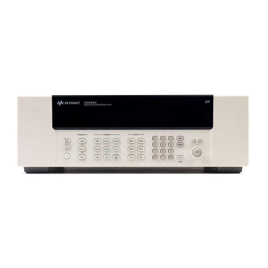
Page 7: Front Panel At A Glance
Utility menu contains settings for Remote I/O (LAN, GPIB, and USB), Date and Time, and other system-related instrument parameters Store/recall menu allows you to save and recall up to six instrument setups Control keys directly control module actions Number keypad enters numerical characters Exponent Cancel key exits a menu without saving changes 34980A Service Guide... - Page 8 Measure keys execute and monitor measurements. Depending on which measurement key you use, you can have complete/direct control over the switching and measurement operation, or you can have the 34980A automatically control these to capture the desired data. 34980A Service Guide...
-
Page 9: Rear Panel At A Glance
LAN connector (10Base T/100Base Tx) USB 2.0 connector External trigger input. For pinout, see page vii. Internal DMM option mark. If you ordered the internal DMM option, the circle is marked black. IEEE 488.2 GPIB Connector Chassis ground screw 34980A Service Guide... -
Page 10: Rear Panel Connector Pinouts
Internal DMM Current Input (Pin 5) ABus1 HI (Pin 9) ABus1 LO (Pin 4) ABus2 HI (Pin 8) ABus2 LO (Pin 3) ABus3 HI (Pin 7) ABus3 LO (Pin 2) ABus4 HI (Pin 6) ABus4 LO (Pin 1) 34980A Service Guide... -
Page 11: Annunciator Display Indicators
Pressing the LOCAL button takes you out of “remote” mode and enables the front panel keys. Safety Interlock ABus Safety Interlock. Terminal block or cables have been removed from the D-sub connector of a module. For more information, see the Agilent 34980A User’s Guide. Trig Waiting for external or manual trigger during scans. -
Page 12: Front Panel Menu Reference
2-wire ohms, 4-wire ohms, temperature, frequency, and period) • Set function parameters Scan • Set up trigger-in parameters • Set up sweep count • Set up sample count Sequence • View sequence command string • Execute sequence • Delete sequence definitions 34980A Service Guide... - Page 13 Select one of four alarms to report alarm conditions on the displayed channel • Configure a high limit, a low limit, or both for the displayed channel • Select the slope (rising or falling edge) for the four alarm output lines 34980A Service Guide...
-
Page 14: Instrument Rack Mounting
Instrument Rack Mounting Using the optional Agilent Y1130A Rack Mount Kit, you can mount the 34980A in a standard 19-inch rack cabinet. This kit includes rack mount brackets and associated hardware required to forward or reverse mount the instrument in the rack cabinet. - Page 15 425.6 mm (16.76 in) 367.7 mm (14.48 in) 101.9 mm (4.01 in) or 70.4 mm (2.78 in) Agilent 34980A Dimensions (shown with Reverse Rack Mount brackets installed) 34980A Service Guide...
- Page 16 34980A Service Guide...
-
Page 17: Table Of Contents
34959A Breadboard Module Specifications and Characteristics Internal DMM Specifications and Characteristics Typical System Speeds Internal DMM Measurement Characteristics System Specifications and Characteristics Product Dimensions To Calculate Total DMM Measurement Error Interpreting Internal DMM Specifications Configuring for Highest Accuracy Measurements 34980A Service Guide... - Page 18 3 Calibration Procedures Agilent Technologies Calibration Services Calibration Interval Adjustment is Recommended Time Required for Calibration Automating Calibration Procedures Recommended Test Equipment Calibration Security Calibration Message Calibration Count Calibration Process Aborting a Calibration in Progress Performance Verification Tests Input Connections...
- Page 19 34938A 20-Channel High-Current GP Switch 5 Disassembly and Repair Electrostatic Discharge (ESD) Precautions Surface Mount Repair Tools Required Basic Disassembly Power Supply Removal Power Supply Disassembly KOM Removal Front Panel Removal Front Panel Disassembly DMM Removal Backplane Removal 34980A Service Guide...
- Page 20 8 Diagrams 34921A Component Locator 34922A Component Locator 34923A Component Locator 34924A Component Locator 34925A Component Locator (Top) 34925A Component Locator (Bottom) 34931A Component Locator 34932A Component Locator 34933A Component Locator 34937A Component Locator 34938A Component Locator 34980A Service Guide...
-
Page 21: Obtaining Service
Agilent 34980A Multifunction Switch/Measure Unit Service Guide Obtaining Service Operating Checklist Types of Service Available Repackaging for Shipment Cleaning Self Test Procedures Electrostatic Discharge (ESD) Precautions Agilent Technologies... -
Page 22: Operating Checklist
Long test leads can act as an antenna causing pick–up of ac signals. Types of Service Available If your instrument fails during the warranty period, Agilent Technologies will repair or replace it under the terms of your warranty. After your warranty expires, Agilent offers repair services at competitive prices. -
Page 23: Repackaging For Shipment
Or contact your Agilent Technologies Representative. Before shipping your instrument, ask the Agilent Technologies Service Center to provide shipping instructions, including what components to ship. Agilent recommends that you retain the original shipping carton for use in such shipments. -
Page 24: Self Test Procedures
On the remote interface, a self–test failure will generate SCPI error –330 and a supplemental message indicating one of the test numbers shown in the table on page Calibration Errors The table on page 88 shows failures that may occur during a calibration. 34980A Service Guide... -
Page 25: Electrostatic Discharge (Esd) Precautions
• Use a conductive wrist strap to reduce static charge accumulation. • Minimize handling. • Keep replacement parts in original static–free packaging. • Remove all plastic, foam, vinyl, paper, and other static–generating materials from the immediate work area. • Use only anti–static solder suckers. 34980A Service Guide... - Page 26 Obtaining Service 34980A Service Guide...
-
Page 27: Specifications
Agilent 34980A Multifunction Switch/Measure Unit Service Guide Specifications Multiplexer Module Specifications and Characteristics Matrix Modules Specifications and Characteristics GP Actuator Module Specifications and Characteristics RF and Microwave Module Specifications and Characteristics 34945A/34945EXT Module Specifications and Characteristics 34950A 64-channel Digital I/O Specifications and Characteristics... -
Page 28: Multiplexer Module Specifications And Characteristics
° Includes 0.5 C temperature reference sensor and 0.5 C terminal block isothermal gradient error. Measured under worst case loading of the mainframe. See 34980A User's Guide for information on supported external reference sensors. With 100 input protection resistors. - Page 29 1 week. Switching relays for 2k cycles prior to use typically corrects this problem. Agilent recommends the use of 4-wire ohms for resistance measurements and the Hi-Z input impedance configuration for voltage measurements. Applies to 34921A, 34922A, 34923A, and 34924A. 34980A Service Guide...
- Page 30 With in-rush resistors bypassed. Bypassing resistors reduces lifetime of relays. See the rated load relay life characteristics. Speeds are for 4½ digits, delay 0, display off, autozero off, and within bank. With 100 input protection resistors. 34980A Service Guide...
-
Page 31: Matrix Modules Specifications And Characteristics
1 week. Switching relays for 2k cycles prior to use typically corrects this problem. Agilent recommends the use of 4-wire ohms for resistance measurements and the Hi-Z input impedance configuration for voltage measurements. Applies to 34931A, 34932A. 34980A Service Guide... - Page 32 4 ms/4 ms 0.5 ms/0.5 ms 0.35 ms/0.10 ms Analog bus backplane connection Bank 2 Bank 2 Bank 2 source, 50 load, differential measurements verified (Sdd21) With in-rush resistors bypassed. With 100 input protection resistors. 34980A Service Guide...
-
Page 33: Gp Actuator Module Specifications And Characteristics
Form A — user configurable Analog bus backplane connection DC or AC RMS voltage, channel-to-channel or channel-to-earth. Limited to 6 W of channel resistance power loss per module. source, 50 load, differential measurements verified (S21). 34980A Service Guide... -
Page 34: Rf And Microwave Module Specifications And Characteristics
34942A) For more detailed specifications, see the N1810TL for the 34946A and N1810UL for the 34947A. The M9046A and M9047A requires N1810 Switch Options 124 (24 volt coils), 201 (D submin. 9-pin conn.), and 402 (Position Indicators) 34980A Service Guide... - Page 35 For more detailed specifications, see the N1810TL for the 34946A and N1810UL for the 34947A. The M9046A and M9047A requires N1810 Switch Options 124 (24 volt coils), 201 (D submin. 9-pin conn.), and 402 (Position Indicators) sec maximum duration Max power is 1 W between 30 MHz and 1 GHz for CISPR 11 compliance 34980A Service Guide...
-
Page 36: 34945A/34945Ext Module Specifications And Characteristics
LED indicators (current mode drivers) Channels Supply voltage 5 V nominal 5 mA nominal LED drive current (programmable 1 to 20 mA) Compliance voltage 0.8 V 34945EXT Dimensions 11.2 x 4.5 x 1.5 inches high with distribution boards installed 34980A Service Guide... -
Page 37: 34950A 64-Channel Digital I/O Specifications And Characteristics
4 mA < Iout < 24 mA Vout (H) 1.6 V < Vout < 5 V Vcc (< 2V) 215 < Rpullup < 1 k -4 mA < Iout < -24 mA Vcc (> 2V) 215 < Rpullup < 10 k 34980A Service Guide... - Page 38 System clock generator characteristics 20 MHz – 10 Hz configurable Frequency divide-by-n 24-bits, programmable on/off Vout 1.66 V – 5 V Accuracy 100 ppm Configurable by bank Lower current drive at lower voltages Maximum threshold setting of 3V 34980A Service Guide...
-
Page 39: 34951A 4-Channel D/A Converter Specifications And Characteristics
C of T or *CAL? 90-day: ± (0.09% + 5.0 A) < 2 A , 20 Hz to 250 kHz into 250 Ripple and noise Compliance voltage ±12 V Max open circuit voltage < ± 22 V 34980A Service Guide... - Page 40 TTL compatible (3.3 V logic, 5 V tolerant) Input impedance > 10 k, DC Maximum rate: 10 MHz Clock output Level TTL compatible into 1 k (3.3 V logic) 50 typical Output impedance Maximum rate 10 MHz Accuracy ± 100 ppm (continued) 34980A Service Guide...
-
Page 41: 34952A Multifunction Module Specifications And Characteristics
Vin(H) (max) < 42 V with external open drain pull-up Alarm Maskable pattern match or state change Speed 4 ms (max) alarm sampling Latency 5 ms (typical) to 34980A alarm output Read/write speed 95/s Totalize input characteristics Max count –... -
Page 42: 34959A Breadboard Module Specifications And Characteristics
Channel 1 and 2 8 configure bits as input or output Channel 3 3 output bits Dimensions (L x W x H) 5.4 x 7.5 x 0.9 inches (without PC board) 5.4 x 7.5 x 0.7 inches (with PC board) 34980A Service Guide... -
Page 43: Internal Dmm Specifications And Characteristics
50 which can occur on modules that have been out of service or following relay inactivity for periods of greater than 1 week. Using 4-wire measurements or switching relays for 2k cycles prior to use typically corrects this problem. Add 50 V error for 34923/24/33. 34980A Service Guide... - Page 44 Typically 30% of reading error at 1 MHz, limited to 1 x 10 volt-hertz Input > 100 mV. For 10 mV inputs multiply % of reading error x 10. For 1 second aperture (6½ digits). Specified only for inputs > 10 mA. For AC filter slow. 34980A Service Guide...
- Page 45 49 to 200 °C to 600 °C 0.06 °C 0.003 °C – 2.1 k Thermistor 2.2k, 5k, 10k 80 °C to 150 °C 0.08 °C 0.002 °C – For total measurement accuracy, add temperature probe error. 34980A Service Guide...
-
Page 46: Typical System Speeds
Readings were made with minimum NPLC, delay 0, display off, autozero off. All times include the issue of “READ?” and the retrieval of data. CLOSE or OPEN bus transfer times allowed to overlap previous command. Command parse times overlap current activity until I/O latency dominant. 34980A Service Guide... - Page 47 1038 Speeds are for 4½ digits, delay 0, display off, autozero off. Scanning is within bank on the same module. Add 10 ms for between banks or modules. Add additional time for filter setting on ACV. 34980A Service Guide...
-
Page 48: Internal Dmm Measurement Characteristics
Fast 200 Hz – 300 kHz Input impedance 1 M ±2% in parallel with 150 pF Input protection 300 Vrms all ranges Resistance Measurement method Selectable 4-wire or 2-wire ohms Current source Referenced to LO input 34980A Service Guide... - Page 49 Selectable on 100 , 1 k, and10 k ranges Offset compensation 10% of range per lead for 100 and 1 k ranges. Maximum lead resistance 1 k on all other ranges Input protection 300 V on all ranges 34980A Service Guide...
- Page 50 1 plc/16.7 ms (20 ms) 60 dB < 1 plc 0 dB For 1 k unbalance in LO lead For power line frequency ±0.08% For power line frequency ±1% use 75 dB or ±2.5% use 60 dB 34980A Service Guide...
- Page 51 Maximum reading rates for 0.01% of AC step additional error. Additional settling delay required when input DC level varies. ½ ½ ½ digits = 22 bits; 5 digits = 18 bits; 4 digits = 15 bits For external trigger or remote operation using default settling delay (Delay Auto) Maximum limit with default settling delays defeated 34980A Service Guide...
-
Page 52: System Specifications And Characteristics
System features Per-channel math Individual Mx+B scaling and calculated real time min/max/average Power fail recovery Save switch states Counts each relay closure and stores on module, Relay maintenance user resettable Real-time clock Battery-backed, 20-year typical life 34980A Service Guide... - Page 53 National Instruments Test Stand, Measurement Studio, LabWindows/CVI, LabVIEW, Switch Executive Microsoft Visual Studio.NET, C/C++, Visual Basic 6 Storage at temperatures above 40°C will decrease battery life. Load IO Libraries Version M for Windows NT support or version 14.0 for Windows 98 SE support. 34980A Service Guide...
-
Page 54: Product Dimensions
22.4 mm (0.88 in) 2X 88.85 mm (3.50 in) 74.26 mm 128.8 mm (2.92 in) (5.07 in) 2X 93.6 mm (3.68 in) 5.5 mm (0.22 in) SQ M3.5 x 0.6 Thread 4 Places 404.0 mm (15.90 in) 34980A Service Guide... -
Page 55: To Calculate Total Dmm Measurement Error
The following table shows the reading error applied to the internal DMM’s 24-hour dc voltage specification. Range Input Level Reading Error Reading Error (% of reading) Voltage 150 V 10 Vdc 10 Vdc 0.0015 15V 10 Vdc 1 Vdc 0.0015 1.5 V 10 Vdc 0.1 Vdc 0.0015 34980A Service Guide... - Page 56 0.0020% x 5 Vdc 10 Vdc = 50 V Range error = 0.0005% = 100 V + 50 V Total Error 150V 0.0030% of 5 Vdc 30 ppm of 5 Vdc 34980A Service Guide...
-
Page 57: Interpreting Internal Dmm Specifications
20% overrange capability can display a measurement with up to 1,200,000 counts of resolution. This corresponds to about 0.0001% (1 ppm) of full scale, or 21 bits including the sign bit. All four specifications are equivalent. 34980A Service Guide... - Page 58 This is a common temperature range for many operating environments. You must add additional temperature coefficient errors to the accuracy specification if you are operating the instrument outside a 23°C ± 5°C temperature range (the specification is per °C). 34980A Service Guide...
-
Page 59: Configuring For Highest Accuracy Measurements
• Use 4-wire ohms and enable offset compensation for the best resistance accuracy. AC Voltage and AC Current Measurements: Set the resolution to 6 digits. • Select the slow ac filter (3 Hz to 300 kHz). Frequency and Period Measurements: Set the resolution to 6 digits. 34980A Service Guide... - Page 60 Specifications 34980A Service Guide...
- Page 61 Agilent 34980A Multifunction Switch/Measure Unit Service Guide Calibration Procedures Agilent Technologies Calibration Services Calibration Interval Adjustment is Recommended Time Required for Calibration Automating Calibration Procedures Recommended Test Equipment Calibration Security Calibration Message Calibration Count Calibration Process...
-
Page 62: Agilent Technologies Calibration Services
Whatever calibration interval you select, Agilent recommends that complete re-adjustment should always be performed at the calibration interval. This will assure that the 34980A will remain within specification for the next calibration interval. This criteria for re-adjustment provides the best long-term stability. -
Page 63: Time Required For Calibration
The instrument must be unsecured prior to initiating the calibration procedure (see “Calibration Security" on page 49). For further information on programming the instrument, see Chapter 2 in the 34980A User's Guide. For information about errors that may occur during the calibration procedure, see “Calibration Errors"... -
Page 64: Recommended Test Equipment
J Type Calibrated ± 0.1 × Thermocouple Reference Junction 34921A with 34921T Only Triple Point Cell [1] Relay contact resistance Agilent Y1131A ± 0.001 resolution All switch modules [1] Optional test if not using relay cycle count. 34980A Service Guide... -
Page 65: Calibration Security
68. Use the command to secure or CALibration:SECure:STATe <mode>,<code> unsecure the instrument. Refer to the 34980A Programmer's Reference Help File for complete information. To Unsecure the Instrument Without the Security Code To unsecure the instrument without the correct security code, follow the steps below. -
Page 66: Calibration Message
“0”. Since the value increments by one for each calibration point, a complete calibration may increase the value by many counts. • The calibration count is also incremented with calibrations of the 34951A 4-Ch DAC and DAC channels on the 34952A multifunction module. • Remote Interface Command: CALibration:COUNt? {<slot>|MAINframe|DMM} 34980A Service Guide... -
Page 67: Calibration Process
705 Cal:Aborted. You may also generate errors 740 through 746. If this occurs, you should not use the instrument until a complete re-adjustment has been performed. For a list of calibration error numbers, see page 34980A Service Guide... -
Page 68: Performance Verification Tests
This command returns a “+0” if all the self-tests pass, or a “+1” if a failure occurred. Depending upon the number and type of modules installed, this command may take up to 2½ minutes to complete. You may need to set an appropriate interface time-out value. 34980A Service Guide... - Page 69 If the instrument fails performance verification, adjustment or repair is required. Adjustment is recommended at every calibration interval. If adjustment is not made, you must guard band, using no more than 80% of the specifications, as the verification limits. 34980A Service Guide...
-
Page 70: Input Connections
Use shielded twisted pair PTFE insulated cables to reduce settling and NOT E noise errors. Connect the shield to the source LO output. PTFE is a registered trademark of E.I. du Pont de Nemours and Company. 34980A Service Guide... -
Page 71: Dmm Test Considerations
“0” output is correct. If necessary, the measurements can be referenced to the calibrator’s “0” output using Mx + B scaling (see Chapter 2 in the 34980A User's Guide). You will need to set the offset for each range of the measuring function being verified. - Page 72 Q: Quick performance verification test points. Zero offset calibration using a multifunction calibrator is NOT NOT E recommended. The calibrator and cabling offset can be large and unstable causing poor offset calibration of the internal DMM. 34980A Service Guide...
- Page 73 Add a 1-second channel delay when using Fluke 5700 in 2-wire compensated mode. This avoids response time issues with 2-wire compensation when 34980A’s current source contains a pulse. [3] Verify only, no adjustment required.
- Page 74 The 50 kHz ac voltage test points may fail performance verification if NOT E the DMM internal shields have been removed and reinstalled. See “Gain Adjustment" on page 63 for further information on how to recalibrate the ac voltage function. 34980A Service Guide...
- Page 75 ± 600 µA 10 mA 1 kHz ± 1.41 mA ± 1.41 mA ± 1.41 mA 1 kHz ± 1.4 mA ± 1.4 mA ± 1.4 mA [1] Verify only, no adjustment. Q: Quick performance verification test points. 34980A Service Guide...
- Page 76 ± 0.1 Hz ± 0.1 Hz 100 kHz ± 6 Hz ± 10 Hz ± 10 Hz [1] Verify only, No adjustment. For this test, isolate the calibrator’s output from earth ground. Q: Quick performance verification test points. 34980A Service Guide...
-
Page 77: Optional Ac Performance Verification Tests
± 7 mV ± 9 mV ± 10 mV 1 kHz 10 V ± 3.4 mV ± 4.5 mV ± 4.6 mV 100 mV 1 kHz 10 V ± 13 mV ± 14 mV ± 14 mV 34980A Service Guide... -
Page 78: Internal Dmm Adjustments
Set the DC VOLTS function. Send the value 0.000000 to the instrument using the CALibration:VALue command. 0.000000 Calibrate the instrument using the command. CALibration? Perform the “Zero Offset Verification" on page 55 to check zero calibration results. 34980A Service Guide... -
Page 79: Gain Adjustment
• During the ac voltage gain adjustments, some of the dc voltage gain constants are used. Perform the dc voltage gain calibration before the ac voltage gain calibration. Never turn off the instrument during a Gain Adjustment. This may cause NOT E calibration memory for the present function to be lost. 34980A Service Guide... - Page 80 100 kHz – [1] Valid frequencies are as follows: 1 kHz ± 10% for the 1 kHz calibration, 45 kHz–100 kHz for the 50 kHz calibration, and 10 Hz ± 10% for the 10 Hz calibration. 34980A Service Guide...
- Page 81 Perform the appropriate Gain Verification Test to check the calibration results. Repeat steps 1 through 5 for each gain verification test point shown in the tables. Each range in the gain adjustment procedure takes less than 20 seconds NOT E to complete. 34980A Service Guide...
- Page 82 (from step 3). Using the previous example values, enter 10 µV minus 10.001 volts or –10.000990 volts. When the adjustment finishes, verify that new readings fall within ± 30 µV of the calibrator output minus the offset. 34980A Service Guide...
-
Page 83: Plug-In Module Test Considerations
Keep the input cables as short as possible. • Remove all user wiring and connections from the plug-in modules before verification or adjustment. • Use 4-wire Ohms measurement techniques for checking relay contact resistance. Check directly at the terminals where possible. 34980A Service Guide... -
Page 84: 34951A 4-Ch Isolated Dac Module
When this type of adjustment is made, the calibration count (see page 50) is not advanced. • If the instrument is unsecured for calibration, the adjustments are written to non-volatile calibration memory. The calibration count (see page 50) is advanced. 34980A Service Guide... - Page 85 34951A Verification Test Connections The DAC outputs can be measured using an external voltmeter, or using a test fixture such as the one shown below, with the internal DMM via the ABus connector on the instrument’s rear panel. 34980A Service Guide...
- Page 86 When measuring the 0 mA output value, apply the offset value from step 1 to the measured value. Repeat steps 2 through 5 for channels 2, 3 and 4. Remove the input test connector. 34980A Service Guide...
- Page 87 ± 9.5 A 5 mA ± 5 A 0 mA ± 9.5 A -5 mA ± 14 A -10 mA ± 18.5 A -15 mA ± 23 A -20 mA [1] Apply a measured “0” offset to this measurement. 34980A Service Guide...
- Page 88 The command returns a value of “+0” if the calibration is successful. A returned value of “+1” indicates a calibration failure. Following the auto-calibration procedure, the DMM is left in its reset NOT E state (DCV). 34980A Service Guide...
-
Page 89: 34952A Multifunction Module
For each analog output (channel 6 and channel 7), set each output value in the table on the next page. Compare measurement results to the appropriate test limits shown in the table. It is not necessary to test the voltage output at the full rated 10 mA load. NOT E 34980A Service Guide... - Page 90 Measure the module output. Send the measured value to the module with the following command: CALibration:POINt? <value> The command returns a “+0” to indicate the calibration on the channel is completed. Repeat steps 3 and 4 for channel 7. 34980A Service Guide...
-
Page 91: Relay Plug-In Modules
Channel 11, the count on the Bank 1 relay, and returns the greater of the two. In addition, the cycle count on the two channels within the same physical relay package, will always be equal. Therefore, the cycle count for Channels 11 and 12 will always be equal. 34980A Service Guide... - Page 92 Relay Contact Resistance Verification (Optional) The Agilent Y1131A Verification/Diagnostic Software Kit contains software and hardware used to test the relay switching modules available for the Agilent 34980A Multifunction Switch/Measure Unit. The software provides module–specific tests to assist you with troubleshooting possible relay failures and predicting system maintenance requirements.
-
Page 93: Thermocouple Reference Junction 34921A (Optional)
INTERNAL REF SENS:TEMP:TRAN:TYPE TC,(@1021) SENS:TEMP:TRAN:TC:TYPE J,(@1021) SENS:TEMP:NPLC 10,(@1021) SENS:TEMP:TRANS:TC:RJUN:TYPE INT,(@1021) Subtract the thermocouple error from the measured temperature. Verify the result is within ± 1.0 °C of the known temperature (set in step 4). 34980A Service Guide... - Page 94 Calibration Procedures 34980A Service Guide...
- Page 95 Agilent 34980A Multifunction Switch/Measure Unit Service Guide Troubleshooting and Diagnostics Troubleshooting Hints Power Supply Product Firmware Updates Instrument Errors Error Numbers Isolate a Problem with a Plug-In Module Relay and FET Replacement 34921A 40-Channel Armature Multiplexer with Low Thermal Offset...
-
Page 96: Troubleshooting Hints
If the self test still fails, remove the internal DMM from the instrument. The instrument should turn on and pass self-test without the internal DMM installed. Disassembly procedures begin on page 117. Self-test errors are described beginning on page 34980A Service Guide... -
Page 97: Power Supply
As new product features and enhancements become available, you can easily update your mainframe and plug-in module firmware to ensure optimum compatibility. The latest firmware updates are available from the Agilent 34980A product page at www.agilent.com/find/34980AUpdates. Front Panel Operation: Utility > FIRMWARE > UPDATE Once you have downloaded the latest mainframe firmware (see above), ... -
Page 98: Instrument Errors
View key. Error conditions are also summarized in the Status Byte Register. For more information on the SCPI Status System for the Agilent 34980A, see Status System Introduction. The interface-specific and global error queues are cleared by the... - Page 99 (the final key press cancels the scroll). All errors are cleared when you exit the menu. Remote Interface Operation SYSTem:ERRor? Read and clear one error from the queue Errors have the following format (the error string may contain up to 80 characters): -113,"Undefined header" 34980A Service Guide...
-
Page 100: Error Numbers
"Configuration memory lost; memory corruption detected" -315 "Configuration memory lost; due to firmware revision change" -321 "Out of memory; use definite length block for large traces" -350 "Error queue overflow" -350 "DMM processor error queue overflowed" -410 "Query INTERRUPTED" -420 "Query UNTERMINATED" 34980A Service Guide... - Page 101 "Not able to accept unit names longer than 3 characters" "Not able to accept character in unit name" "Not able to perform on more than one channel" "Not able to recall state: it is empty" "Not able to recall state: DMM enable changed" 34980A Service Guide...
- Page 102 "Cannot achieve requested resolution" "Not able to achieve requested resolution" "Cannot use overload as math reference" "Not able to null channel in overload" "Command not allowed in local" "Not able to execute command in local mode" "Unknown Dmm Inguard Error" 34980A Service Guide...
- Page 103 "DC high voltage attenuator failed" "Ohms 1 mA source failed" "AC rms zero failed" "AC rms full scale failed" "Frequency counter failed" "Cannot calibrate precharge" "Unable to sense line frequency" "I/O processor does not respond" "I/O processor failed self-test" 34980A Service Guide...
- Page 104 "Cal checksum failed, GPIB address" "Cal checksum failed, internal data" "Cal: mainframe cal memory write failure" "Cal: invalid while cal in progress" "Firmware and FPGA revision mismatch" "Cal: no cal in progress" "DMM relay count data lost" 34980A Service Guide...
- Page 105 "Firmware update error; bad checksum for download complete" "Firmware update error; download in progress" "Firmware update error; unable to complete download" "Firmware update error; invalid programming address" "State has not been restored" "Operation has not been implemented" 34980A Service Guide...
- Page 106 "Module reported ABus safety interlock activated" "Module reported overtemperature" "Module backplane error" "Backplane module transaction failed" "Safety Interlock prevents completion of this command. Check Terminal connection." "Revision mismatch between module firmware and FPGA" "Backplane interrupt line stuck asserted, service disabled" 34980A Service Guide...
- Page 107 "Illegal operation when channel drive enabled" "Switch failed to verify as expected" "Internal channel drive illegal for remote slave module" "Overcurrent detected" "Remote modules configured in an illegal topology" "Illegal operation when remote module's channel drive disabled" "Module hardware: unexpected transaction termination" 34980A Service Guide...
-
Page 108: Isolate A Problem With A Plug-In Module
Module replacement 34947A Triple 1x2 SPDT unterminated microwave switch Module replacement 34950A 64-bit digital I/O with memory and counter Module replacement 34951A 4-channel isolated D/A converter Module replacement 34952A Multifunction module Module replacement 34959A Breadboard module Module replacement 34980A Service Guide... -
Page 109: Relay And Fet Replacement
The Agilent Y1131A Verification/Diagnostic Software Kit is a recommended tool and contains software and hardware used to test the relay switching modules available for the Agilent 34980A Multifunction Switch/Measure Unit. The software provides module–specific tests to assist you with troubleshooting possible relay failures and predicting system maintenance requirements. -
Page 110: 34921A 40-Channel Armature Multiplexer With Low Thermal Offset
For the 34921A, relay and fuse part numbers are given on page 128 and the component locator is shown on page 138. The table below shows the relationship of channel numbers to relay numbers. Bank 1 Bank 2 34980A Service Guide... - Page 111 K913 K923 K914 K924 Current* Current* K841, K841S, K843, K843S, F1041 F1043 K842, K842S, K844, K844S, F1042 F1044 Current Backplane K931 *The current switches use two relays to create a “make-before-break” circuit. You should replace both relays. 34980A Service Guide...
-
Page 112: 34922A 70-Channel Armature Multiplexer
For the 34922A, relay part numbers are given on page 128 and the component locator is shown on page 139. The table on the next page shows the relationship of channel numbers to relay numbers. Bank 1 Bank 2 Channel Relay Channel Relay 34980A Service Guide... - Page 113 K757 K623 K758 K624 K759 K625 K760 K626 K761 K627 K762 K628 K763 K629 K764 K630 K765 K631 K766 K632 K767 K633 K768 K634 K769 K635 K770 Backplane Backplane K811 K821 K812 K822 K813 K823 K814 K824 34980A Service Guide...
-
Page 114: 34923A 40/80-Channel Reed Multiplexer
Using program commands or the mainframe front panel, you can control each of the channel switches individually, and configure this module for differential (2-wire or 4-wire) or single- ended (1-wire) mode. Refer to the simplified schematic for two- or four-wire modes. 34980A Service Guide... - Page 115 071, 072 K502 033, 034 K403 073, 074 K503 035, 036 K404 075, 076 K504 037, 038 K405 077, 078 K505 039, 040 K405 079, 080 K505 Backplane Backplane K611 K621 K612 K622 K613 K623 K614 K624 34980A Service Guide...
-
Page 116: 34924A 70-Channel Reed Multiplexer
921-924), four on each bank that can connect the bank relays to the system Analog Buses. Through ABus1 and ABus2 you can connect any of the channels to the system DMM for voltage or resistance measurements. See the simplified schematic below. 34980A Service Guide... - Page 117 K503 K404 K504 K409 K509 K407 K507 K402 K502 K404 K505 K406 K506 K407 K507 K409 K509 K402 K502 K401 K501 K404 K505 K406 K506 K406 K506 Backplane Backplane K611 K621 K612 K622 K613 K623 K614 K624 34980A Service Guide...
-
Page 118: 34925A 40/80-Channel Optically-Isolated Fet Multiplexer
Using program commands or the mainframe front panel, you can control each of the FET channel switches individually, and configure this module for differential (2-wire or 4-wire) or single- ended (1-wire) mode. Refer to the simplified 2-, 4-wire schematic below. 34980A Service Guide... - Page 119 U716 033, 034 U617 073, 074 U717 035, 036 U618 075, 076 U718 037, 038 U619 077, 078 U719 039, 040 U620 079, 080 U720 Backplane Relay Backplane Relay K800 K804 K801 K805 K802 K806 K803 K807 34980A Service Guide...
-
Page 120: 34931A Dual 4X8 Armature Matrix
3 and column 4 (all columns consisting of two digits; in this case the digits are 04). See the simplified schematic below. Matrix 1 and Matrix 2 are electrically separate from one another. Matrix Relays: Armature latching. Analog Bus Relays: Armature non-latching. 34980A Service Guide... - Page 121 K7301 K8701 K7302 K8702 K7303 K8703 K7304 K8704 K7305 K8705 K7306 K8706 K7307 K8707 K7308 K8708 K7401 K8801 K7402 K8802 K7403 K8803 K7404 K8804 K7405 K8805 K7406 K8806 K7407 K8807 K7408 K8808 Backplane K921 K922 K923 K924 34980A Service Guide...
-
Page 122: 34932A Dual 4X16 Armature Matrix
3 and column 15 (all columns consisting of two digits; in this case the digits are 15). See the simplified schematic below. Matrix 1 and Matrix 2 are electrically separate from one another. Matrix Relays: Armature latching. Analog Bus Relays: Armature non-latching 34980A Service Guide... - Page 123 K8514 K7115 K8515 K7116 K8516 K7201 K8601 K7202 K8602 K7203 K8603 K7204 K8604 K7205 K8605 K7206 K8606 K7207 K8607 K7208 K8608 K7209 K8609 K7210 K8610 K7211 K8611 K7212 K8612 K7213 K8613 K7214 K8614 K7215 K8615 K7216 K8616 34980A Service Guide...
- Page 124 K7401 K8801 K7402 K8802 K7403 K8803 K7404 K8804 K7405 K8805 K7406 K8806 K7407 K8807 K7408 K8808 K7409 K8809 K7410 K8810 K7411 K8811 K7412 K8812 K7413 K8813 K7414 K8814 K7415 K8815 K7416 K8816 Backplane K921 K922 K923 K924 34980A Service Guide...
-
Page 125: 34933A Dual/Quad 4X8 Reed Matrix
Troubleshooting and Diagnostics 34933A Dual/Quad 4x8 Reed Matrix Using program commands or the front panel of the 34980A, you can configure the 34933A dual/quad 4x8 reed matrix module for differential (2-wire) mode or single-ended (1-wire) mode. The 34933A module contains 100 ... - Page 126 NOTE: All series resistors shown are 100Ω. NOTE: Three-digit channel numbers are derived from the intersection of the rows and columns, columns having two digits. The intersectoin shown here represents Channel 308 (Row 3, Column 8). 34980A Service Guide...
- Page 127 34933A One-Wire Mode For the 34933A, relay part numbers are given on page 132 and the component locator is shown on page 146. The table on the next page shows the relationship of channel numbers to relay numbers. 34980A Service Guide...
- Page 128 343, 443 K607 144, 244 K506 344, 444 K606 145, 245 K504 345, 445 K604 146, 246 K503 346, 446 K603 147, 247 K502 347, 447 K602 148, 248 K501 348, 448 K601 Backplane K704 K703 K702 K701 34980A Service Guide...
-
Page 129: 34937A 32-Channel Gp Switch
Relay Channel Relay K601 K615 K602 K616 K603 K617 K604 K618 K605 K619 K606 K620 K607 K621 K608 K622 K609 K623 K610 K624 K611 K625 K612 K626 K613 K627 Form A Form A K629 K631 K630 K632 34980A Service Guide... -
Page 130: 34938A 20-Channel High-Current Gp Switch
148. The table below shows the relationship of channel numbers to relay numbers. Bank 1 Bank 2 Channel Relay Channel Relay K501 K511 K502 K512 K503 K513 K504 K514 K505 K515 K506 K516 K507 K517 K508 K518 K509 K519 K510 K520 34980A Service Guide... - Page 131 Agilent 34980A Multifunction Switch/Measure Unit Service Guide Disassembly and Repair Electrostatic Discharge (ESD) Precautions Surface Mount Repair Tools Required Basic Disassembly Power Supply Removal Power Supply Disassembly KOM Removal Front Panel Removal Front Panel Disassembly DMM Removal Backplane Removal Agilent Technologies...
-
Page 132: Disassembly And Repair
Tools Required The following tools are required for basic disassembly. • T20 Torx driver • 3/16” nut driver (for rear panel connectors) • 9/32” nut driver (for GP-IB connector) • #2 Pozidrive (for fan) 34980A Service Guide... -
Page 133: Basic Disassembly
Remove all plug-in modules. Using a T-20 Torx driver, loosen the five captive screws in the rear bezel and remove the bezel. The metal cover will now slide off. 34980A Service Guide... -
Page 134: Power Supply Removal
Swing the module out and disengage it from the sheet metal at the back. Note: For testing purposes, y ou can stand the power supply on end and insert it into slots in the mainframe as shown. 34980A Service Guide... -
Page 135: Power Supply Disassembly
To disassembly the power supply, press the catch on the power supply shield and slide the shield to release it. Remove the safety shield. Using a T20 Torx, remove the four screws holding the power supply printed circuit board to the sheet metal. 34980A Service Guide... -
Page 136: Kom Removal
Use a 9/32” nut driver to remove the nuts holding the GP-IB connector on the rear panel. Use a T20 Torx to remove the four screws holding the KOM printed circuit assembly to the mainframe. Lift out the assembly. 34980A Service Guide... -
Page 137: Front Panel Removal
Stand the entire assembly on its side to make removal easier. Pull to unclip the ground connector from the mainframe. Swing the two clips securing the front panel connector ribbon cable to the front panel circuit board and unplug the connector. 34980A Service Guide... -
Page 138: Front Panel Disassembly
Pull to remove the knob. Use a 7/16” nut driver to remove the nut from the knob shaft. Remove the four T20 Torx screws from the circuit board and lift the circuit board out. You can now lift out the keypad. 34980A Service Guide... -
Page 139: Dmm Removal
Unplug the ribbon cable at the top of the DMM assembly. Remove the two T20 Torx screws from the left front side of the mainframe. Move the DMM assembly to the right and lift out. Unplug the input cable from the backplane printed circuit board. 34980A Service Guide... -
Page 140: Backplane Removal
Use a 3/16” nut driver to remove the rear panel Analog Bus DB9 connector. Unclip the connector cable from the mainframe. Remove the five T20 Torx screws holding the backplane assembly to the chassis and lift the printed circuit assembly out. 34980A Service Guide... - Page 141 Agilent 34980A Multifunction Switch/Measure Unit Service Guide Replaceable Parts To Order Replaceable Parts Backdating and Part Changes Mainframe Replaceable Parts 34921A Replaceable Parts 34922A Replaceable Parts 34923A Replaceable Parts 34924A Replaceable Parts 34925A Replaceable Parts 34931A Replaceable Parts 34932A Replaceable Parts...
-
Page 142: Replaceable Parts
Identify the parts by the Agilent part number shown in the replaceable parts list. Provide the instrument model number and serial number. Backdating and Part Changes Always refer to Chapter 7, “Backdating” before attempting repair or before ordering replaceable parts. Parts changes, if any, are documented in the backdating chapter. 34980A Service Guide... -
Page 143: Mainframe Replaceable Parts
34980-48001 Keypad 34980-48307 Front Panel 34980-66502 PCA - Front Panel 34980-49301 Window 34970-87401 Knob 34980-04104 Mainframe Cover, sheet metal 34980-48301 Rear Bezel 5041-9167 Foot 34980-48305 Cover, Analog Output 34980-48304 Cover, Slot 34980-66504 PCA, DMM 34980-68501 Fan Assembly 34980A Service Guide... -
Page 144: 34921A Replaceable Parts
K749, K750, K751, K752, K753, K754, K755, K756, K757, K758, K759, K760, K761, K762, K763, K764, K765, K766, K767, K768, K769, K770 K811, K812, K813, K814, 0490-1954 RELAY 2C 12VDC-COIL Omron G6S-2-DC12 K821, K822, K823, K824 2A 250VAC 34980A Service Guide... -
Page 145: 34923A Replaceable Parts
U617, U618, U619, U620, U701, U702, U703, U704, U705, U706, U707, U708, U709, U710, U711, U712, U713, U714, U715, U716, U717, U718, U719, U720 K800, K801, K802, K803, 0490-1954 RELAY 2C 12VDC-COIL Omron G6S-2-DC12 K804, K805, K806, K807 2A 250VAC 34980A Service Guide... -
Page 146: 34931A Replaceable Parts
K8508, K8601, K8602, K8603, K8604, K8605, K8606, K8607, K8608, K8701, K8702, K8703, K8704, K8705, K8706, K8707, K8708, K8801, K8802, K8803, K8804, K8805, K8806, K8807, K8808 K921, K922, K923, K924 0490-1954 RELAY 2C 12VDC-COIL Omron G6S-2-DC12 2A 250VAC 34980A Service Guide... -
Page 147: 34932A Replaceable Parts
K8707, K8708, K8709, K8710, K8711, K8712, K8713, K8714, K8715, K8716, K8801, K8802, K8803, K8804, K8805, K8806, K8807, K8808, K8809, K8810, K8811, K8812, K8813, K8814, K8815, K8816 K921, K922, K923, K924 0490-1954 RELAY 2C 12VDC-COIL Omron G6S-2-DC12 2A 250VAC 34980A Service Guide... -
Page 148: 34933A Replaceable Parts
Component Locator Agilent P/N Description Vendor Vendor K501, K502, K503, K504, 0490-2731 RELAY 1A 9VDC-COIL Matsushita K505, K506, K507, K508, 5A 30VDC THRU HOLE DSP1A-L2- K509, K510, K511, K512, DC9V-F K513, K514, K515, K516, K517, K518, K519, K520 34980A Service Guide... -
Page 149: 34946A And 34947A Replaceable Parts
Schaumberg, IL 60173-5302 U.S.A. Coto Technology 55 DuPont Drive Providence, RI 02907 U.S.A Matsushita c/o Panasonic Electric Works Corporation of America 629 Central Avenue New Providence, NJ 07974 U.S.A Littelfuse 800 East Northwest Highway Des Plains, IL 60016 U.S.A 34980A Service Guide... - Page 150 Replaceable Parts 34980A Service Guide...
-
Page 151: Backdating
Agilent 34980A Multifunction Switch/Measure Unit Service Guide Backdating Agilent Technologies... - Page 152 Backdating Backdating This chapter contains information necessary to adapt this manual to instruments and assemblies not directly covered by the current content. There are no backdated assemblies at the time of this printing. 34980A Service Guide...
-
Page 153: Diagrams
Agilent 34980A Multifunction Switch/Measure Unit Service Guide Diagrams 34921A Component Locator 34922A Component Locator 34923A Component Locator 34924A Component Locator 34925A Component Locator (Top) 34925A Component Locator (Bottom) 34931A Component Locator 34932A Component Locator 34933A Component Locator 34937A Component Locator... -
Page 154: 34921A Component Locator
K724 K613 K617 K737 K733 K618 K732 K612 K738 K729 K603 K609 K723 K614 K607 K734 K727 K610 K730 K616 K736 K722 K739 K602 K619 K731 K725 K611 K605 K606 K615 K726 K735 K601 K620 K721 K740 34980A Service Guide... -
Page 155: 34922A Component Locator
K752 K630 K765 K607 K742 K739 K604 K766 K631 K621 K756 K614 K749 K611 K629 K746 K764 K736 K601 K625 K760 K632 K610 K767 K745 K626 K620 K755 K761 K616 K615 K751 K750 K606 K741 K605 K740 34980A Service Guide... -
Page 156: 34923A Component Locator
Diagrams 34923A Component Locator K621 K611 K503 K403 34980A Service Guide... -
Page 157: 34924A Component Locator
Diagrams 34924A Component Locator K621 K611 34980A Service Guide... -
Page 158: 34925A Component Locator (Top)
Diagrams 34925A Component Locator (Top) K800 K802 K806 K804 K803 K805 K807 K801 U606 U616 U613 U618 U620 U706 U703 U713 U718 U720 U612 U614 U619 U701 U707 U712 U714 U719 U601 U603 34980A Service Guide... -
Page 159: 34925A Component Locator (Bottom)
Diagrams 34925A Component Locator (Bottom) U715 U705 U708 U717 U702 U615 U605 U608 U617 U602 U710 U709 U704 U716 U711 U610 U609 U604 U607 U611 34980A Service Guide... -
Page 160: 34931A Component Locator
K7305 K7405 K7205 K7105 K8705 K8805 K8605 K8505 K7304 K7404 K7402 K7104 K8704 K8804 K8604 K8504 K7303 K7403 K7203 K7103 K8703 K8803 K8603 K8503 K7302 K7402 K7202 K7102 K8702 K8802 K8602 K8502 K7301 K7401 K7201 K7101 K8701 K8801 K8601 K8501 34980A Service Guide... -
Page 161: 34932A Component Locator
K7305 K7405 K7205 K7105 K8705 K8805 K8605 K8505 K7304 K7404 K7402 K7104 K8704 K8804 K8604 K8504 K7303 K7403 K7203 K7103 K8703 K8803 K8603 K8503 K7302 K7402 K7202 K7102 K8702 K8802 K8602 K8502 K7301 K7401 K7201 K7101 K8701 K8801 K8601 K8501 34980A Service Guide... -
Page 162: 34933A Component Locator
Diagrams 34933A Component Locator K704 K507 K607 K506 K606 K505 K605 K504 K604 K503 K603 K502 K602 K501 K601 34980A Service Guide... -
Page 163: 34937A Component Locator
Diagrams 34937A Component Locator K612 K602 K626 K616 K614 K617 K603 K628 K632 K629 K630 K631 34980A Service Guide... -
Page 164: 34938A Component Locator
Diagrams 34938A Component Locator K519 K508 K509 K518 K502 K513 K503 K512 34980A Service Guide...