Agilent Technologies 34980a Getting Started Manual
Multifunction switch and measure device
Hide thumbs
Also See for 34980a:
- User manual (349 pages) ,
- Service manual (164 pages) ,
- Application note (20 pages)
Table of Contents
Advertisement
Contents of Your Shipment.................................................1
Front Panel at a Glance.......................................................2
Rear Panel at a Glance........................................................3
Supplemental Safety Notices.............................................4
Removing a Slot Cover ........................................................5
Installing a Module ..............................................................5
Installing a Module for Use with Cables.................... 5
Wiring and Installing a Terminal Block............................7
Wiring a Terminal Block................................................ 7
Installing a Terminal Block........................................... 8
Operating the Front Panel Keyboard.................................9
Operating the Channel Relay .................................... 9
Menu Example: Setting the Date and Time............. 10
Using the Measure Keys............................................. 10
for a Measurement ................................................... 11
a Measurement ......................................................... 12
Agilent Technologies 34980A
Multifunction Switch/Measure Unit
Getting Started Guide
Connecting the 34980A to Your Computer ................... 15
Connecting Over LAN ..................................................15
Connecting Over GPIB .................................................18
Connecting Over USB...................................................19
Communicating with the 34980A ................................... 20
Exploring the 34980A Web Interface Over LAN........... 21
Launching the Web Interface.....................................21
Displaying the Browser Web Control Page .............22
Selecting the "Allow Full Control" Mode.................22
Closing and Opening Channel Relays .......................23
Modifying the Channel Configuration.......................23
34980A Documentation Map............... Inside Rear Cover
Selecting the LAN Network Type.........................15
Connecting Via Site LAN........................................16
Connecting Via Isolated (Non-Site) LAN.............17
Advertisement
Table of Contents

Related Manuals for Agilent Technologies 34980a


Summary of Contents for Agilent Technologies 34980a
-
Page 1: Table Of Contents
Agilent Technologies 34980A Multifunction Switch/Measure Unit Getting Started Guide Contents of Your Shipment..........1 Connecting the 34980A to Your Computer ....15 Front Panel at a Glance............2 Connecting Over LAN ..........15 Rear Panel at a Glance............3 Selecting the LAN Network Type......15 Supplemental Safety Notices..........4... -
Page 2: Safety Notices
Warranty Safety Notices The material contained in this document CAUTION © Agilent Technologies, Inc. 2004, 2005 is provided “as is,” and is subject to being changed, without notice, in future No part of this manual may be A CAUTION notice denotes a editions. -
Page 3: Contents Of Your Shipment
If you ordered optional terminal blocks or cables with your modules, they will be included in the shipment with your modules. You will find information about the modules in the 34980A User’s Guide . If you have questions about your shipment, or if you need information about warranty, service,... -
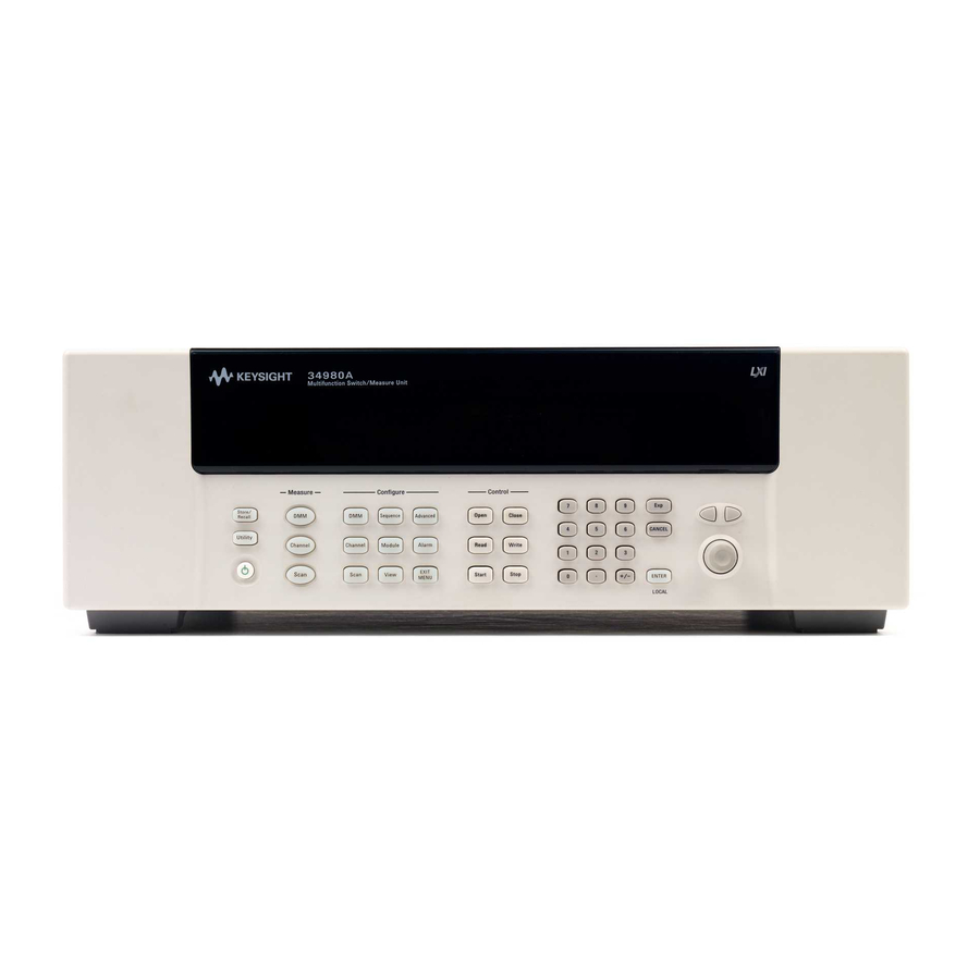
Page 4: Front Panel At A Glance
34980A automatically control the switching and measurement. For more information on using the front-panel menus, see the 34980A User’s Guide . 34980A Getting Started Guide... -
Page 5: Rear Panel At A Glance
Caution. Refer to accompanying description. Alternating current. Mainframe chassis ground. Access to Analog Buses (shown with cover installed). See 34980A User’s Guide for connector pinout. Module shown installed in Slot 1 Slot Identifier (slots are numbered 1 through 8) Module Chassis Ground Screw... -
Page 6: Supplemental Safety Notices
Agilent Technologies assumes no liability for the customer’s failure to comply with these requirements. -
Page 7: Removing A Slot Cover
Removing a Slot Cover Your 34980A is shipped from the factory with one slot uncovered and the remaining seven slots covered. When performing tasks in this guide to become familiar with the instrument, you will install a plug-in module into Slot 1. When you are ready to install additional modules, follow the procedure below to remove a slot cover. -
Page 8: Installing A Module For Use With Terminal Blocks
Installing a Module for Use with Terminal Blocks All of the 34980A plug-in modules, except the RF and microwave modules, can be used with a compatible terminal blocks (optional accessories 349 xx T). The optional terminal blocks provide screw terminals or solder cup connections for your external wiring. If you plan to use an optional terminal block, follow the procedure below. -
Page 9: Wiring And Installing A Terminal Block
Before you begin this task, make sure you have disconnected power from all external field wiring you will be connecting to the terminal block. For plug-in module pinout diagrams and additional information, refer to the 34980A User’s Guide , which is shipped with your 34980A mainframe. -
Page 10: Installing A Terminal Block
Terminal Block Support Sleeve 34980A Mainframe Step 2. Carefully rotate the levers …until both levers are locked in the upward as shown… closed position. NEXT STEP: Go to “Operating the Front Panel Keyboard” on page 9. 34980A Getting Started Guide... -
Page 11: Operating The Front Panel Keyboard
Operating the Front Panel Keyboard This section gives an overview on operating the 34980A from the front panel keyboard. For additional information, see the 34980A User's Guide . Before you can operate the front panel keyboard, connect the power cord to the 34980A and turn on the power. -
Page 12: Menu Example: Setting The Date And Time
Configure group) is stored and recalled whenever you select that channel. Scan When you press Scan, the 34980A controls all the relays required to make a series of sequential measurements, even across multiple channels with unlike measurement functions. -
Page 13: Menu Example: Configuring The Internal Dmm For A Measurement
This example uses the internal DMM for a measurement. If you have disabled your internal DMM, or don’t have one installed in your 34980A, skip this example. Use the following instructions for any of the multiplexer modules (34921A, 34922A, 34923A, 34924A, or 34925A). -
Page 14: Menu Example: Configuring A Channel For A Measurement
(to select the cursor position) to enter a custom channel label. 9. Press the lighted Channel key to save the assigned channel label and all other changes you made. Continued on next page… 34980A Getting Started Guide... - Page 15 15. With the Channel key still lighted, turn the knob to display channel 1016. You should see measurements start for DC VOLTS (your previously configured function for channel 16). Continued on next page… 34980A Getting Started Guide...
- Page 16 14. • You monitored channels with the Channel key (in Measure key group) activated. Using the knob, you scrolled between channels 14 and 16 to alternatively start, view, and stop continuous measurements on the channels. 34980A Getting Started Guide...
-
Page 17: Connecting The 34980A To Your Computer
Connecting the 34980A to Your Computer To easily connect the 34980A to your PC, configure and verify your connection, you can use the Agilent IO Libraries Suite, the E2094M Agilent IO Libraries for Windows, or an equivalent. Agilent IO Libraries Suite for Windows 98/2000/ME/XP. For information and to install, use the •... -
Page 18: Connecting Via Site Lan
LAN STATUS OFF ON DHCP BOOT (Use knob to select ON) (Use knob to select 8. Now you can use the 34980A Web Browser Interface to IP_ADDRESS) access and control the instrument. See page 21 for more EXIT MENU information on using the Web Interface. -
Page 19: Connecting Via Isolated (Non-Site) Lan
I/O software on your computer. 9. Use the Connection Expert utility of the Agilent IO Libraries Suite to add the 34980A and verify a connection. When identifying the instrument, it is easiest if you use the IP address noted in step 5 above. -
Page 20: Connecting Over Gpib
I/O software, refer to documentation included with (Use knob to select YES) that software. 7. The 34980A is shipped from the factory with a default Utility GPIB address of 9. To change the address, refer to the flow diagram shown to the right. -
Page 21: Connecting Over Usb
Therefore, you do not need to insert the CD when the Found New Hardware Wizard instructs you to do so. 4. Use the Connection Expert utility of the Agilent IO Libraries Suite to verify that the 34980A is displayed under the USB interface. -
Page 22: Communicating With The 34980A
To install drivers and their associated Help files, refer to the 34980A Product Reference CD-ROM , which is included with the 34980A User’s Guide . This CD-ROM also contains a collection of example programs for your reference. -
Page 23: Exploring The 34980A Web Interface Over Lan
Exploring the 34980A Web Interface Over LAN You can use the 34980A’s Web Browser Interface for remote access and control of the instrument via a ® Java-enabled Web browser, such as Microsoft Internet Explorer. Using the Web Interface, you can configure, troubleshoot, and monitor your system remotely. -
Page 24: Displaying The Browser Web Control Page
If desired, you can use the 34980’s front panel Utility menu to assign a password for use with the 34980A Web Interface. Once specified, the password must be provided to transition from the Observe Only mode to the Allow Full Control mode. -
Page 25: Closing And Opening Channel Relays
The Channel Configuration dialog box for that channel is displayed. 2. As an example, change the label on Channel 1001 to “DUT_1”. Click OK. 34980A Getting Started Guide... -
Page 26: Sending Scpi Commands Via The Web Interface
You must be in the Allow Full Control mode to send instrument commands to the 34980A. The Web Interface provides a utility to send SCPI commands to the 34980A via the SCPI Command Interface window. The procedure below shows how to access this window and send commands. - Page 27 Learn about the 34980A front- 34980A User’s Guide Shipped as a printed manual with the panel menu content and operation 34980A and a PDF file on the 34980A Product Reference CD-ROM. Or download the User’s Guide from the Agilent Web site at: www.agilent.com/find/34980A.
- Page 28 Agilent Technologies, Inc. Printed in Malaysia Edition 2 April 2005 E0405 *34980-90004* Getting Started Guide 34980-90004...