Agilent Technologies 34980A User Manual
Multifunction switch/measure unit
Hide thumbs
Also See for 34980A:
- User manual (349 pages) ,
- Service manual (164 pages) ,
- Getting started manual (28 pages)
Table of Contents
Advertisement
Quick Links
Download this manual
See also:
User Manual
Agilent References in this manual
NOTICE: This document contains references to Agilent Technologies. Agilent's former Test and Measurement
business has become Keysight Technologies. For more information, go to:
www.keysight.com
About this manual
We've added this manual to the Keysight website in an effort to help you support your product. This manual
provides the best information we could find. It may be incomplete or contain dated information.
Support for your product
You can find information about technical and professional services, product support, and equipment repair and
service on the web:
www.keysight.com
Select your country from the drop-down menu at the top. Under
Services
on
. The web page that appears next has contact information specific to your country.
For more detailed product information, go to: www.keysight.com/find/
i.e., for the M9514A, use:
Hypertext links to documents on agilent.com are no longer active. Use this substitution to access PDF files:
Broken links have the form: http://cp.literature.agilent.com/litweb/pdf/<
Substitute links with this form: http://literature.cdn.keysight.com/litweb/pdf/<
<literature_part_number>
Where
For service notes, use:
www.keysight.com/find/servicenotes
www.keysight.com/find/M9514A
has the form: M9300-90001.pdf
Errata
Electronic Test and Measurement
<product model>
literature_part_number
>
literature_part_number
, click
>
Advertisement
Table of Contents

Related Manuals for Agilent Technologies 34980A


Summary of Contents for Agilent Technologies 34980A
-
Page 1: About This Manual
Errata Agilent References in this manual NOTICE: This document contains references to Agilent Technologies. Agilent’s former Test and Measurement business has become Keysight Technologies. For more information, go to: www.keysight.com About this manual We’ve added this manual to the Keysight website in an effort to help you support your product. This manual provides the best information we could find. - Page 3 Agilent 34980A Multifunction Switch/Measure Unit Mainframe User’s Guide Agilent Technologies, Inc. Printed in Malaysia Edition 7 March 2013 E0313 *34980-90005* 34980-90005 Agilent Technologies...
-
Page 5: Declaration Of Conformity
DoC/search.htm. You can then search agreement and written consent from user customers. Agilent provides this Agilent Technologies, Inc. as governed by product number to find the latest customary commercial license in Soft- Declaration of Conformity. -
Page 6: Safety Symbols
Agilent in Do Not Remove the your country of specific location. You can Instrument Cover also contact your Agilent Technologies Representative. Only qualified, service-trained personal who are aware of the hazards involved should remove instrument covers. Always... -
Page 8: Table Of Contents
Instrument Rack Mounting ..........Operating the 34980A from the Front Panel Keyboard ..... . - Page 9 ....42 Connecting the 34980A to Your Computer....... .
- Page 10 ......... . 148 Agilent 34980A Mainframe User’s Guide...
- Page 11 4 Introduction to the Plug-In Modules for the 34980A User’s Guides for the 34980A’s Plug-In Modules ......
-
Page 12: Introduction To The 34980A
Mainframe User’s Guide Introduction to the 34980A This chapter provides an overview of a computer- based data acquisition and measurement control system using the Agilent 34980A Multifunction Switch/Measure Unit and typical plug- in modules. Data Acquisition Overview Measurement Software Data Acquisition Circuitry... -
Page 13: Data Acquisition Overview
Introduction to the 34980A Data Acquisition Overview You can use the Agilent 34980A as a stand- alone instrument, but for most applications you will want to take advantage of its PC connectivity and remote operation capabilities. A simplified data acquisition system is shown below. -
Page 14: Measurement Software
Agilent 34832A BenchLink Data Logger Pro is a Windows®- based application available on CD from Agilent. It is designed to make it easy to use the 34980A with your PC (over GPIB, USB or LAN) for collecting and analyzing data. You program the desired measurement, scan and data logging requirements using an intuitive, tabbed spreadsheet environment;... - Page 15 Other Software for Automated Testing with Multiple Instruments These software tools can also be used with the 34980A: • Agilent IO Libraries Suite (shipped on CD with the 34980A) • Agilent IntuiLink • Agilent VEE (an evaluation copy of the VEE Pro software is shipped on CD with the 34980A) •...
-
Page 16: Data Acquisition Circuitry
Introduction to the 34980A Data Acquisition Circuitry As shown below, the 34980A's main system processor controls all of the basic functionality of the instrument. This is where the instrument communicates with the plug- in modules, interacts with command transactions over the remote interfaces, and controls the optional internal DMM. -
Page 17: Plug-In Modules
Introduction to the 34980A Plug-In Modules The 34980A offers a complete selection of plug- in modules to give you high- quality measurement, switching, and control capabilities. The plug- in modules communicate with the main system processor via the internal digital bus. The multiplexer modules also connect to the internal DMM via the internal Analog Buses. -
Page 18: Transducers And Sensors
TTL levels Alarm Limits The 34980A has four alarms which you can configure to alert you when a reading exceeds specified limits on a channel during a scan. You can assign a high limit, a low limit, or both to any configured channel in the scan list. -
Page 19: Signal Routing And Switching
Signal Routing and Switching The switching capabilities of the plug- in modules available with the 34980A provide test system flexibility and expandability. You can use the switching plug- in modules to route signals to and from your test system or multiplex signals to the internal DMM or external instruments. -
Page 20: Matrix Switching
You can use General Purpose (GP) switches to control power connections to your DUTs, control status indicators, or actuate external power relays or solenoids. The GP switches for the 34980A are available in two switch configurations as shown below. Form C... -
Page 21: Rf And Microwave Switching
RF and Microwave Switching A variety of RF and microwave switch modules are also available for the 34980A. This includes RF multiplexers (34941A, 34942A), SPDT switching from dc to 20 GHz (34946A, 34947A), and a switch/attenuator driver module (34945A) that allows you to control switches or attenuators external to the 34980A mainframe. -
Page 22: Measurement Input
Introduction to the 34980A Measurement Input The 34980A allows you to combine a DMM (either internal or external) with multiplexer channels to create a scan. During a scan, the instrument connects the internal DMM to the configured multiplexer channels one at a time and makes a measurement on each channel. -
Page 23: Analog-To-Digital Conversion (Adc)
The ADC takes a prescaled dc voltage from the signal- conditioning circuitry and converts it to digital data for output and display on the 34980A front panel. The ADC governs some of the most basic measurement characteristics. These include measurement resolution, reading speed, and the ability to reject spurious noise. -
Page 24: Scanning
Ch 2 Ch 3 Ch 4 Ch 5 Ch 6 Channel Delay (0 to 60 seconds) • You can also program a time delay between channels in the scan list (see “Channel Delay” on page 120). Agilent 34980A Mainframe User’s Guide... -
Page 25: Scanning With External Instruments
Scanning With External Instruments If your application doesn't require the built- in measurement capabilities of the 34980A, you can order the mainframe without the internal DMM. In this configuration, you can use the 34980A for signal routing or control applications. If you install a multiplexer plug- in module, you can use the system for scanning with an external instrument. - Page 26 (including channel delay). The 34980A outputs a Channel Closed pulse. In response, the external instrument must notify the 34980A when it has finished its measurement and is ready to advance to the next channel in the scan list. For more information, see “Scanning...
-
Page 27: The Digital Modules
Each port has a separate channel number on the module and contains 8- bits. You can combine ports to read 16- or 32- bit words. Bit 0 Bit 7 Bit 8 Bit 15 Bit 16 Bit 23 Bit 24 Bit 31 Agilent 34980A Mainframe User’s Guide... -
Page 28: Totalizer
- 1). The count rolls over to "0" after reaching the maximum allowed value. You can configure the totalizer to read without affecting the count or reset the count to zero without losing any counts. Agilent 34980A Mainframe User’s Guide... -
Page 29: Control Output
Introduction to the 34980A Control Output In addition to signal routing and measurement, you can also use the 34980A to provide simple control outputs. For example, you can control external high- power relays using the GP switch modules or a digital output channel. -
Page 30: Voltage (Dac) Output
Vdc, in 500 V steps on any or all four channels. You can set the output current to any value between - 20 mA and +20 mA, in 630 nA steps on any or all four channels. Agilent 34980A Mainframe User’s Guide... -
Page 31: The Actuator / General-Purpose Switches
• The actuator switches can also be used to control power devices. When used with high- power devices, however, it is critical that you provide protection to the switch from capacitive and inductive loads to ensure maximum relay life. Agilent 34980A Mainframe User’s Guide... -
Page 32: Getting Started
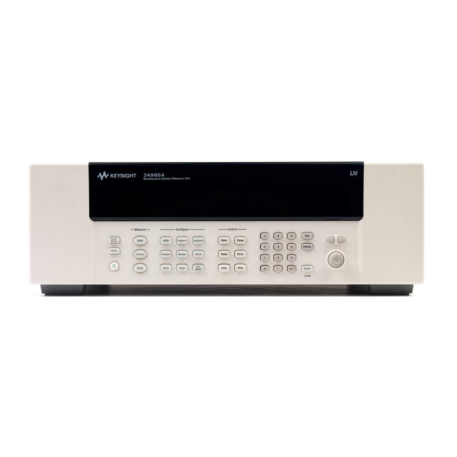
Agilent 34980A Multifunction Switch/Measure Unit Mainframe User’s Guide Getting Started This chapter provides an overview of the 34980A’s controls, displays and connections; module assembly, wiring and installation instructions; and some basics of operation with examples. It is designed to allow you to gain quick familiarity with the instrument and start using it. -
Page 33: Front Panel At A Glance
Getting Started Front Panel at a Glance The On/Standby switch is used to toggle the 34980A between On and Standby modes only. To turn the unit off, remove the power cord. The Utility key accesses menus to configure Remote I/O (LAN, GPIB, and USB) operation, set Date and Time, and configure other system-related instrument parameters. -
Page 34: Rear Panel At A Glance
LAN connector (10Base T/100Base Tx) USB 2.0 connector External trigger input. For pinouts, see page Internal DMM option mark. If you ordered the internal DMM option, the circle is marked black. IEEE 488.2 GPIB Connector Chassis ground screw Agilent 34980A Mainframe User’s Guide... -
Page 35: Rear Panel Connector Pinouts
Getting Started Rear Panel Connector Pinouts External Trigger/Alarms Connector (Male D-Sub) Analog Bus Connector (Female D-Sub) Agilent 34980A Mainframe User’s Guide... -
Page 36: Annunciator Display Indicators
User’s Guides for the appropriate Multiplexer Modules. Trig Lit when the 34980A is waiting for an external or manual trigger during scans. Indicates an over-temperature condition. When lit, one or more general purpose (34937A/34938A) modules have reached their over-temperature limits. -
Page 37: Installing And Connecting Modules
Getting Started Installing and Connecting Modules For most applications, prior to using the 34980A you will select and install modules, and make connections with terminal blocks or cabling. The following sections illustrate module and terminal block installation. Removing a Slot Cover... -
Page 38: Installing A Module
Installation is now complete. Installing a Module for Use with Terminal Blocks All of the 34980A plug- in modules, except the RF and microwave modules, can be used with a compatible terminal blocks (optional accessories 349xxT), which provide screw terminals or solder cup connections for your external wiring. - Page 39 Install the module into a mainframe slot until it fully seats with the backplane connector. Using a Pozidriv #1 screwdriver, tighten the two screws to secure the module in the mainframe. Installation of the support sleeve is now complete. Agilent 34980A Mainframe User’s Guide...
-
Page 40: Wiring And Installing A Terminal Block
Gently push the tab in the direction of the arrow. While pushing the tab (Step 1), lift the clear plastic cover from the edge near the D- sub connectors. Slide the cover from under the tab holders and remove the cover. Agilent 34980A Mainframe User’s Guide... - Page 41 Push the levers on the terminal block to the fully- open position as shown below. Then slide the terminal block into the instrument- mounted support sleeve... …until the terminal block stops at the two points indicated by the arrows below. Agilent 34980A Mainframe User’s Guide...
- Page 42 Getting Started Terminal Block Support Sleeve 34980A Mainframe Carefully rotate the levers upward as shown… …until both levers are locked in the closed position. Agilent 34980A Mainframe User’s Guide...
-
Page 43: Instrument Rack Mounting
Getting Started Instrument Rack Mounting The Agilent 34980A Mainframe can be mounted in a standard 19 inch instrument rack or in an Agilent rack cabinet. Orientation can be either forward mounted (front panel facing the front of the cabinet) or reverse mounted (rear panel facing the front of the cabinet). - Page 44 Getting Started 425.6 mm (16.76 in) 367.7 mm (14.48 101.9 mm (4.01 in) or 70.4 mm (2.78 in) Agilent 34980A Dimensions (shown with Reverse Rack Mount brackets installed) Agilent 34980A Mainframe User’s Guide...
-
Page 45: Operating The 34980A From The Front Panel Keyboard
Before you can operate the front panel keyboard, connect the power NOT E cord to the 34980A and turn on the power. If the instrument does not power on properly, contact Agilent Technologies Technical Support. At power on, all segments on the front panel are displayed and all lighted keys temporarily turn on. -
Page 46: Front Panel Menu Reference
Recall stored states, the power-down state, the factory reset state, or a preset state. The Utility menu U se to configure system-related instrument parameters. You can: • Connect and configure the 34980A to use over LAN, GPIB, or USB; • Set the real time clock and calendar; •... - Page 47 Configure a high limit, a low limit, or both for the displayed channel • Select the slope (rising or falling edge) for the four alarm output lines The Exit Menu Key Press to leave the current menu, saving all changes made in that menu Agilent 34980A Mainframe User’s Guide...
-
Page 48: Menu Example 1: Setting The Time And Date
Getting Started Menu Example 1: Setting the Time and Date In this example, you will learn the fundamentals of using the 34980A front- panel menus by setting the date and time. Begin by pressing the Utility menu key, then use the Utility key, knob and arrow keys to navigate the menu as shown below. -
Page 49: Menu Example 2: Opening And Closing Channel Relays
With channel 1027 selected (shown in green channel field on display), toggle the Close and Open keys to close and open the selected channel. Note that the display shows OPEN or CLOSED, indicating the status of the channel. Agilent 34980A Mainframe User’s Guide... -
Page 50: Using The Measure Keys
Depending on which measurement key you select, you can have complete/direct control over the switching and measurement operations, or you can allow the 34980A to automatically control the measurement to capture the desired data. The three keys in the Measure group are: •... -
Page 51: Menu Example 3: Configuring The Dmm For A Measurement
(34921A, 34922A, 34923A, 34924A, or 34925A). If you have disabled your internal DMM, don't have one installed in your 34980A, or are not using a multiplexer module, skip this example. Make sure you have a multiplexer module installed in slot 1. Select any channel on this module (the channel number is shown in green channel field on display). - Page 52 The internal DMM acted as a stand- alone instrument and measured whatever ac voltages happened to be present on the Analog Buses. Pressing DMM (in the Measure key group) also allowed you to continuously monitor measurements on the front panel. Agilent 34980A Mainframe User’s Guide...
-
Page 53: Menu Example 4: Configuring A Channel For A Measurement
This example uses the internal DMM for a measurement. It can be used with any of the multiplexer modules (34921A, 34922A, 34923A, 34924A, or 34925A). If you have disabled your internal DMM, don't have one installed in your 34980A, or are not using a multiplexer module, skip this example. - Page 54 Press the lighted Channel key to save the assigned channel label and all other changes you made. Press the Channel key (in the Measure key group). Note that the key lights, the required relays automatically close, and dc voltage measurements begin. Agilent 34980A Mainframe User’s Guide...
- Page 55 • You configured channel 14 for ac voltage measurements, then started, viewed results, and stopped continuous ac voltage measurements on channel 14. • You scrolled between channels 14 and 16 to alternatively start, monitor, and stop continuous measurements on the channels. Agilent 34980A Mainframe User’s Guide...
-
Page 56: Connecting The 34980A To Your Computer
Connecting the 34980A to Your Computer To easily configure and verify an interface connection between the NOT E 34980A and your PC, you can use the Agilent IO Libraries Suite or an equivalent. The Agilent IO Libraries Suite—along with installation instructions—is •... -
Page 57: Connecting Over Lan
• An Isolated LAN network is defined as a local area network (LAN) in which computers and LAN- enabled instruments are not connected to a site LAN. Use the crossover cable provided with the 34980A to make a direct connection between the 34980A and your computer. Crossover cables are also supported by many newer LAN switches or routers. - Page 58 34980A to LAN wall outlets. Make sure power is applied to your computer and verify that the operating system is fully booted. Then apply power to the 34980A. Using the flow diagram shown below, navigate through the 34980A front- panel Utility menu.
- Page 59 LAN settings. Write down the IP address in the space below: 34980A IP Address: ___________________________ Press EXIT MENU. Now you can use the integrated 34980A Web Browser Interface to access and control the instrument. See “Launching the Web Interface” on page 54 for more information.
- Page 60 34980A. Make sure power is applied to your computer and verify that the operating system is fully booted. Then apply power to the 34980A. Using the flow diagram below, navigate through the 34980A front- panel Utility menu. At the IO PORT menu, select LAN. At the LAN SETTINGS menu, select MODIFY and set DHCP to OFF (note that ON is the factory default state).
- Page 61 IP address and other LAN settings. Write down the IP address in the space below: 34980A IP Address: ___________________________ Press EXIT MENU. Now you can use the integrated 34980A Web Browser Interface to access and control the instrument. See “Launching the Web Interface” on page 54 for more information.
-
Page 62: Connecting Over Gpib
Press Utility again to save any changes and exit the Utility menu. Use the Connection Expert utility of the Agilent IO Libraries Suite to add the 34980A and verify a connection. If you have installed any other I/O software, refer to documentation included with that software. -
Page 63: Connecting Over Usb
Then apply power to the 34980A. The Found New Hardware Wizard will automatically start and guide you through configuring the 34980A as a USB device. To install the software automatically, accept all defaults. If you installed the Agilent IO Libraries software, this also installed the NOT E required low-level software drivers. -
Page 64: Communicating With The 34980A
To install drivers and their associated Help files, refer to the 34980A Product Reference CD shipped with your 34980A. This CD also contains a collection of example programs for your reference. -
Page 65: Launching The Web Interface
Either refer to the IP address you wrote on page 48 page 50, or use the 34980A's front panel Utility menu to read the IP address. After entering the appropriate IP address, the 34980A Web Interface's Welcome Window should appear. -
Page 66: Displaying The Browser Web Control Page
Browser Web Control page. From this page, you can view and modify the configuration of the modules currently installed in the 34980A. When you first launch this page, the configuration of the module in the lowest numbered slot is shown (shown in bold text). -
Page 67: Selecting The "Allow Full Control" Mode
Setting a Web Browser Password If desired, you can control access to the 34980A Web Interface using password protection. As shipped from the factory, no password is set. To set a password (available from the front panel only), navigate to the... -
Page 68: Closing And Opening Channel Relays
You can also open and close the four Analog Bus relays by left- clicking the graphics of these relays. The Analog Bus Overview display located near the top of the window shows the slot- by- slot status of the four Analog Buses. Agilent 34980A Mainframe User’s Guide... -
Page 69: Modifying The Channel Configuration
The Channel Configuration dialog box for that channel is displayed. As an example, change the label on Channel 1001 to DUT_1 . Click Agilent 34980A Mainframe User’s Guide... -
Page 70: Sending Scpi Commands Via The Web Interface
NOT E commands to the 34980A. The Web Interface provides a utility to send SCPI commands to the 34980A via the SCPI Command Interface window. The procedure below shows how to access this window and send commands. Press the button at the top of the Web Browser Control Commands page to launch the SCPI Command Interface window. - Page 71 You can use the button to access a syntax SCPI Quick Reference summary of all SCPI commands for the 34980A. For basic SCPI command syntax and examples, see “SCPI Language Conventions” page 66. Agilent 34980A Mainframe User’s Guide...
-
Page 72: 34980A Documentation Map
These chapters are part of this Mainframe menu content and operation page 22 User’s Guide, shipped as a printed manual with the 34980A and a PDF file on the 34980A “Operating the 34980A from the Product Reference CD. You can also download Front Panel Keyboard”... - Page 73 Getting Started Agilent 34980A Mainframe User’s Guide...
-
Page 74: Features And Functions
Mainframe User’s Guide Features and Functions This chapter provides detailed information about the features of the Agilent 34980A, whether you will be operating the instrument from the front panel or over the remote interface. For general information about the plug- in modules, see Chapter 4, “Introduction to the Plug- In Modules for the... -
Page 75: Front Panel Features
Features and Functions Front Panel Features Front Panel Display The 34980A features a dual- line, alphanumeric display, plus a set of text and symbolic annunciators to indicate operational modes and error conditions. At power on, all segments on the front panel are displayed and all lighted keys temporarily turn on. -
Page 76: Front Panel Controls
• When you have entered all required parameters, the lighting on the menu key will turn off. Front Panel Controls The front panel keys control local operation of the 34980A. They are illustrated and described in detail in “Front Panel at a Glance”... -
Page 77: Basic Operating Modes
34980A. However, for most test applications, the 34980A will be located remotely from the devices under test, and you will send commands to it using its remote interface connectivity modes (e.g. -
Page 78: Rules For Using A Channel List
Features and Functions Rules for Using a Channel List Many of the SCPI commands for the 34980A include a channel list parameter which allows you to specify one or more channels. From the remote interface, the channel number has the form (@sccc), where s is the mainframe slot number (1 through 8) and ccc is the channel number. -
Page 79: Remote Interface Configuration
Features and Functions Remote Interface Configuration To easily configure and verify an interface connection between the NOT E 34980A and your PC, you can use the Agilent IO Libraries Suite or an equivalent. • The Agilent IO Libraries Suite—along with installation instructions—is provided on the Automation-Ready CD, which is shipped with your 34980A. -
Page 80: Gpib Interface
• IP Address • Auto- IP • Subnet Mask • Default Gateway • Host Name • DNS Server • Domain Name Front panel and remote interface instructions for setting these parameters are provided in the following subsections. Agilent 34980A Mainframe User’s Guide... - Page 81 DHCP is typically the easiest way to configure your instrument for remote communication using the LAN interface. If you change the DHCP setting, you must cycle power on the 34980A to activate the new setting. • When DHCP is enabled (factory setting), the instrument will try to obtain an IP address from a DHCP server.
- Page 82 IP address is not used. However, if the DHCP server fails to assign a valid IP address, the currently configured static IP address will be used. If you change the IP address, you must cycle power on the 34980A to activate the new setting.
- Page 83 Features and Functions Auto-IP The Auto- IP standard automatically assigns an IP address to the 34980A when on a network that does not have DHCP servers. If you change the Auto- IP configuration, you must cycle power on the ...
- Page 84 Default Gateway. Contact your network administrator to determine if subnetting is being used and for the correct Subnet Mask. If you change the Subnet Mask, you must cycle power on the 34980A to activate the setting.
- Page 85 Subnet Mask setting. Contact your network administrator to determine if a gateway is being used and for the correct address. If you change the Default Gateway, you must cycle power on the 34980A to activate the new setting.
- Page 86 Host Name The Host Name is the host portion of the domain name, which is translated into an IP address. If you change the Host Name, you must cycle power on the 34980A to activate the new setting. • The default Host Name for the 34980A is “A- 34980A- nnnnn”, where nnnnn represents the last five digits of the instrument’s serial number.
- Page 87 Domain names into IP addresses. Contact your network administrator to determine if DNS is being used and for the correct address. If you change the DNS address, you must cycle power on the 34980A to activate the new setting.
- Page 88 A domain name is a registered name on the Internet, which is translated into an IP address. This feature is available from the remote interface only. If you change the Domain Name, you must cycle power on the 34980A to ...
-
Page 89: Clearing 34980A Memory
Features and Functions Clearing 34980A Memory For security reasons, you may want to clear memory in the 34980A. Volatile Memory The following settings are stored in volatile memory: • All measurement results • Any non- default internal DMM settings • Any non- default channel configurations •... -
Page 90: Analog Bus And Internal Dmm Considerations
Environmental Operating Conditions The 34980A mainframe, including the optional internal DMM, is designed to operate in a temperature range of 0 °C to +55 °C with non- condensing humidity. The maximum humidity is 80% at 40 °C or higher. Do not use in locations where conductive dust or electrolytic salt dust may be present. -
Page 91: Electrical Operating Conditions
Features and Functions Electrical Operating Conditions To avoid electric shock, turn off the 34980A and disconnect or WA RNING de-energize all field wiring to the modules and the Analog Bus connector before removing any module or slot cover. Transients The Analog Buses and the optional internal DMM are designed to safely withstand occasional transient overvoltages up to 1000 Vpeak. -
Page 92: General Measurement Configuration
Overview of Measurement Modes Two modes of operation are available with the 34980A, depending on the level of switching and measurement that you wish to directly control: the Stand- Alone DMM Mode and the Scanning Mode. - Page 93 In the Scanning Mode, the 34980A automatically controls a sequence of measurements using the internal DMM, possibly across multiple channels, and stores the results in memory. The 34980A closes and opens the appropriate channel relays and Analog Bus relays required ...
- Page 94 • If you omit the optional <ch_list> parameter, the MEASure? command applies to the internal DMM. • If you specify a <ch_list>, the MEASure? command performs a “temporary” scan of the specified channels (independent of the present scan list). Agilent 34980A Mainframe User’s Guide...
-
Page 95: Analog Buses
Features and Functions Analog Buses The 34980A provides four 2- wire internal Analog Buses for easier signal routing. You can route your measurements directly to the internal DMM using the 34980A multiplexer and matrix modules, or you can connect to external signals via the Analog Bus connector located on the instrument’s... -
Page 96: Measurement Functions
(range, integration time, etc.). Remote Interface Operation: You can select the measurement function using commands. For example, the following CONFigure MEASure? command configures the specified channel for dc voltage measurements. CONF:VOLT:DC 10,DEF,(@3001) Agilent 34980A Mainframe User’s Guide... -
Page 97: Measurement Range
Remote Interface Operation: You can select the range using parameters in commands. For example, the following CONFigure MEASure? command selects the 10 Vdc range on the specified channel. CONF:VOLT:DC 10,DEF,(@3001) Agilent 34980A Mainframe User’s Guide... -
Page 98: Measurement Resolution
44 on the 34921A). MEAS:CURR:AC? 1,1E-6,(@2041) You can also select the resolution using the commands. For example, SENSe the following command specifies a 2- wire ohms measurement with 100 resolution on channel 1003. SENS:RES:RES 100,(@1003) Agilent 34980A Mainframe User’s Guide... -
Page 99: Custom A/D Integration Time
Remote Interface Operation: You can set the integration time using the commands. For example, the following command specifies an SENSe aperture time of 2 ms for resistance measurements on channel 2001. SENS:RES:APER 0.002,(@2001) Agilent 34980A Mainframe User’s Guide... -
Page 100: Autozero
Front Panel Operation: DMM or Channel (Configure) > AUTO ZERO Remote Interface Operation: The OFF and ONCE parameters have a similar effect. Autozero OFF does not issue a new zero measurement. Autozero ONCE issues an immediate zero measurement. [SENSe:]<function>:ZERO:AUTO {OFF|ONCE|ON} [,(@<ch_list>)] Agilent 34980A Mainframe User’s Guide... -
Page 101: Trigger Delay
CONFigure MEASure? Automatic. • The instrument selects an automatic trigger delay after a Factory Reset command). An Instrument Preset ( command) or *RST SYSTem:PRESet Card Reset ( command) does not change the setting. SYSTem:CPON Agilent 34980A Mainframe User’s Guide... -
Page 102: Automatic Trigger Delays
1.0 second Fast (200 Hz) 120 ms Frequency, Period: AC Filter Trigger Delay Slow (3 Hz) 600 ms Medium (20 Hz) 300 ms Fast (200 Hz) 100 ms Digital Input, Totalize: Trigger Delay 0 seconds Agilent 34980A Mainframe User’s Guide... -
Page 103: Safety Interlock
• The simulation setting is stored in volatile memory and will be lost when power is turned off. To re- enable the simulation mode after power has been off, you must send the command again. Remote Interface Operation: SYSTem:ABUS:INTerlock:SIMulate {OFF|ON} Agilent 34980A Mainframe User’s Guide... -
Page 104: User-Defined Channel Labels
• All user- defined channel labels are stored in non- volatile memory, and do not change when power has been off, after a Factory Reset command), after an Instrument Preset ( *RST SYSTem:PRESet command), or after a stored state is recalled ( command). *RCL Agilent 34980A Mainframe User’s Guide... - Page 105 1. ROUT:CHAN:LABEL:CLEAR:MOD 1 The following command clears all user- defined labels on all modules installed in the 34980A. The factory- default labels are assigned to all channels on all installed modules. ROUT:CHAN:LABEL:CLEAR:MOD ALL Agilent 34980A Mainframe User’s Guide...
-
Page 106: 2-Wire Versus 1-Wire Mode
User’s Guides shipped with the modules. If you change the module configuration, you must cycle power on the 34980A to activate the new setting. • To determine whether the module is in the 2- wire or 1- wire... -
Page 107: Temperature Measurement Configuration
An Instrument Preset *RST command) or Card Reset ( command) does SYSTem:PRESet SYSTem:CPON not change the units setting. Front Panel Operation: DMM or Channel (Configure) > TEMPERATURE > UNITS Remote Interface Operation: UNIT:TEMP {C|F|K}[,(@<ch_list>)] Agilent 34980A Mainframe User’s Guide... -
Page 108: Thermocouple Measurements
If an open connection is detected (greater than 5 k on the 10 k range), the instrument reports an overload condition for that channel (or displays “OPEN T/C” on the front panel). Agilent 34980A Mainframe User’s Guide... -
Page 109: Rtd Measurements
(opens are reported as “+9.90000000E+37”). SENS:TEMP:TRAN:TC:CHECK ON,(@2003) RTD Measurements The instrument supports RTDs with = 0.00385 (DIN/IEC 751) using ITS- 90 software conversions or = 0.00391 using IPTS- 68 software conversions. The default is = 0.00385. Agilent 34980A Mainframe User’s Guide... - Page 110 1003 for 4- wire measurements of an RTD with = 0.00391 (channel 1003 is automatically paired with channel 1023 for the 4- wire measurement). SENS:TEMP:TRAN:FRTD:TYPE 91,(@1003) The following command sets the nominal resistance (R ) to 1000 channel 1003. SENS:TEMP:TRAN:FRTD:RES 1000,(@1003) Agilent 34980A Mainframe User’s Guide...
-
Page 111: Thermistor Measurements
CONF:TEMP THER,5000,(@3001) You can also use the command to select the probe type and SENSe thermistor type. For example, the following command configures channel 1003 for measurements of a 10 k thermistor: SENS:TEMP:TRAN:THERM:TYPE 10000,(@1003) Agilent 34980A Mainframe User’s Guide... -
Page 112: Voltage Measurement Configuration
With AUTO ON, the input resistance is set to >10 G for the three lowest dc voltage ranges. [SENSe:]<function>:IMPedance:AUTO {OFF|ON} [,(@<ch_list>)] If you omit the optional <ch_list> parameter, the command applies to the internal DMM. Agilent 34980A Mainframe User’s Guide... -
Page 113: Ac Low Frequency Filter
The instrument selects the appropriate filter based on the frequency you specify (see table above). [SENSe:]VOLTage:AC:BANDwidth {3|20|200} [,(@<ch_list>)] If you omit the optional <ch_list> parameter, the command applies to the internal DMM. Agilent 34980A Mainframe User’s Guide... -
Page 114: Resistance Measurement Configuration
If you omit the optional <ch_list> parameter, the command applies to the internal DMM. For 4- wire measurements, specify the paired channel in Bank 1 (source) as the <ch_list> channel (channels in Bank 2 are not allowed in the <ch_list>). Agilent 34980A Mainframe User’s Guide... -
Page 115: Current Measurement Configuration
The instrument selects the appropriate filter based on the frequency you specify (see table above). [SENSe:]CURRent:AC:BANDwidth {3|20|200} [,(@<ch_list>)] If you omit the optional <ch_list> parameter, the command applies to the internal DMM. Agilent 34980A Mainframe User’s Guide... -
Page 116: Frequency Measurement Configuration
The instrument selects the appropriate timeout based on the frequency you specify (see table above). [SENSe:]FREQuency:RANGe:LOWer {3|20|200} [,(@<ch_list>)] If you omit the optional <ch_list> parameter, the command applies to the internal DMM. Agilent 34980A Mainframe User’s Guide... -
Page 117: Mx+B Scaling
(“ ”). An Instrument Preset ( command) does not clear the SYSTem:PRESet scaling values and does not turn off scaling. Agilent 34980A Mainframe User’s Guide... - Page 118 Remote Interface Operation: Use the following commands to set the gain, offset, and custom measurement label. CALC:SCALE:GAIN 1.2,(@1003) CALC:SCALE:OFFSET 10,(@1003) CALC:SCALE:UNIT 'PSI',(@1003) After setting the gain and offset values, send the following command to enable the scaling function on the specified channel. CALC:SCALE:STATE ON,(@1003) Agilent 34980A Mainframe User’s Guide...
-
Page 119: Scanning
• Each time you start a new scan, the instrument clears all readings (including alarm data) stored in reading memory from the previous scan. Therefore, the contents of memory are always from the most recent scan. Agilent 34980A Mainframe User’s Guide... - Page 120 Card Reset, etc.) while a scan is running. • If a scan includes a read of the totalizer, the count is reset each time it is read during the scan only when the totalizer reset mode is enabled. Agilent 34980A Mainframe User’s Guide...
-
Page 121: Adding Channels To The Scan List
DMM and others using an external instrument. Readings are stored in 34980A memory only when the internal DMM is used. • The Monitor mode is automatically enabled on all channels that are part of the active scan list (see “Monitor Mode”... - Page 122 READ? Measurements are stored in memory. Each time you initiate a new scan, the instrument will clear the previous set of readings from memory. • To stop a scan in progress, use the command. ABORt Agilent 34980A Mainframe User’s Guide...
-
Page 123: Scan Trigger Source
See “Trigger Count” on page 117 for more information. • Mx+B scaling and alarm limits are applied to measurements during a scan and all data is stored in volatile memory. Agilent 34980A Mainframe User’s Guide... - Page 124 Front Panel Operation: Scan (Configure) > INTERVAL > MANUAL To initiate the scan and store all readings in memory, press the Scan (Measure) key. Note: To stop a scan, press and hold the Scan (Measure) key. Agilent 34980A Mainframe User’s Guide...
- Page 125 See “Trigger Count” on page 117 for more information. • Mx+B scaling and alarm limits are applied to measurements during a manual scanning operation and all data is stored in volatile memory. Agilent 34980A Mainframe User’s Guide...
- Page 126 Select monitor channel ROUT:MON:CHAN (@1003) ROUT:MON:CHAN:ENABLE ON,(@1003) Enable monitoring on channel Enable monitor mode ROUT:MON:STATE ON INIT Initiate the scan Note: To stop a scan, send the command. ABORt Agilent 34980A Mainframe User’s Guide...
- Page 127 Remote Interface Operation: The following program segment configures the instrument for an external scan. TRIG:SOURCE EXT Select external mode Sweep the scan list 2 times TRIG:COUNT 2 Initiate the scan INIT Note: To stop a scan, send the command. ABORt Agilent 34980A Mainframe User’s Guide...
-
Page 128: Trigger Count
(a sweep is one pass through the scan list). The front- panel sample annunciator (“ * ”) turns on during each measurement. Trigger Sweep 1 Sweep 2 Trigger Sweep . . . Sweep Count (1 to 500,000 sweeps) Sweep count Agilent 34980A Mainframe User’s Guide... -
Page 129: Sample Count
DMM measurements (with no scan list). The front- panel sample annunciator (“ * ”) turns on during each measurement. Sample Count (1 to 500,000 samples) Trigger Trigger Sample count for Stand-Alone DMM Mode Agilent 34980A Mainframe User’s Guide... - Page 130 • The instrument sets the sample count to 1 after a Factory Reset command). An Instrument Preset ( command) or *RST SYSTem:PRESet Card Reset ( command) does not change the setting. SYSTem:CPON Front Panel Operation: Scan (Configure) > SAMPLE COUNT Remote Interface Operation: SAMPle:COUNt Agilent 34980A Mainframe User’s Guide...
-
Page 131: Channel Delay
• You can select a unique delay for every channel on the module. • The channel delay is valid only while scanning. If no channels have been assigned to the scan list, the specified channel delay is ignored (no error is generated). Agilent 34980A Mainframe User’s Guide... -
Page 132: Automatic Channel Delays
1 k 2.0 ms 1.0 ms 10 k 2.0 ms 1.0 ms 100 k 25 ms 20 ms 1 M 30 ms 25 ms 10 M 200 ms 200 ms 100 M 200 ms 200 ms Agilent 34980A Mainframe User’s Guide... - Page 133 Interface Operation: The following command enables an automatic channel delay on the specified channels. ROUT:CHAN:DELAY:AUTO ON,(@1003,1013) Selecting a specific channel delay using the ROUTe:CHANnel:DELay command (see “Channel Delay” on page 120) disables the automatic channel delay. Agilent 34980A Mainframe User’s Guide...
-
Page 134: Reading Format
• The format settings are stored in volatile memory and will be lost when power is turned off or after a Factory Reset ( command). *RST Remote Interface Operation: Use the following commands to select the reading format. FORMat:READing:ALARm ON FORMat:READing:CHANnel ON FORMat:READing:TIME ON FORMat:READing:TIME:TYPE {ABSolute|RELative} FORMat:READing:UNIT ON Agilent 34980A Mainframe User’s Guide... -
Page 135: Non-Sequential Scanning
*RCL • The scan order setting is stored in volatile memory and the ordered mode will be enabled when power is turned off or after a Factory Reset command). *RST Remote Interface Operation: ROUTe:SCAN:ORDered {OFF|ON} Agilent 34980A Mainframe User’s Guide... -
Page 136: Viewing Readings Stored In Memory
(however, all readings from a scan in progress at the same time are stored in memory). • The command stores readings in memory. Use the INITiate FETCh? command to retrieve stored readings from memory (the readings are not erased when you read them). Agilent 34980A Mainframe User’s Guide... - Page 137 This allows you to continue a scan without losing data stored in memory (if memory becomes full, new readings will overwrite the first readings stored). The specified number of readings are cleared from memory, starting with the oldest reading. DATA:REMOVE? 12 Agilent 34980A Mainframe User’s Guide...
-
Page 138: Monitor Mode
The count on a totalizer channel is not reset when it is being monitored (the Monitor ignores the totalizer reset mode). • If a channel that is currently being monitored is manually closed or opened, the Monitor operation will be disabled on that channel. Agilent 34980A Mainframe User’s Guide... - Page 139 To read the monitor data from the selected channel or the internal DMM, send the following command. Each reading is returned with measurement units, time stamp, channel number, and alarm status information (see “Reading Format” on page 123). ROUTe:MONitor:DATA? Agilent 34980A Mainframe User’s Guide...
-
Page 140: Scanning With External Instruments
Scanning With External Instruments If your application doesn’t require the built- in measurement capabilities of the 34980A, you can order the mainframe without the internal DMM. In this configuration, you can use the system for signal routing or control applications. - Page 141 “Scan Trigger Source” on page 112. • You can configure the event or action that notifies the 34980A to advance to the next channel in the scan list. Note that the Channel Advance source shares the same sources as the scan trigger. However, an error is generated if you attempt to set the channel advance source to the same source (other than IMMediate) used for the scan trigger.
- Page 142 TRIG:SOUR IMM TRIG:COUN 5 Set trigger count Set channel advance source ROUT:CHAN:ADV:SOUR EXT Initiate the scan INIT To configure the instrument for 4- wire external scanning, send the following command. ROUTe:CHANnel:FWIRe {OFF|ON}, (@<ch_list>) Agilent 34980A Mainframe User’s Guide...
-
Page 143: Alarm Limits
The information stored in the alarm queue is always in absolute time format and is not affected by the command setting. FORMat:READing:TIME:TYPE Agilent 34980A Mainframe User’s Guide... - Page 144 TTL pulse to your control system. You can also initiate a scan sweep (no external wiring required) when an alarm event is logged on a channel. For complete details, refer to “Using the Alarm Output Lines” on page 136. Agilent 34980A Mainframe User’s Guide...
- Page 145 You can configure the instrument to use the status system to generate a Service Request (SRQ) when alarms are generated. Refer to the Agilent 34980A Programmer’s Reference Help file for more information on the Status System. An alarm is enabled on the displayed channel.
-
Page 146: Viewing Stored Alarm Data
Alarm Limit Threshold Crossed Time (3:30:23.000 PM) (0 = No Alarm, 1 = LO, 2 = HI) The following command retrieves scanned readings and alarm data from reading memory (the readings are not erased). FETCH? Agilent 34980A Mainframe User’s Guide... -
Page 147: Using The Alarm Output Lines
(even during a scan) and the alarm data in memory is not cleared (however, data is cleared when you initiate a new scan). The alarm outputs are also cleared when you initiate a new scan. Agilent 34980A Mainframe User’s Guide... - Page 148 Clear all four alarm outputs OUTPUT:ALARM:CLEAR:ALL To select the output configuration for all four output lines, use the following command. OUTPut:ALARm:MODE {LATCh|TRACk} To configure the slope of all four output lines, use the following command. OUTPut:ALARm:SLOPe {NEGative|POSitive} Agilent 34980A Mainframe User’s Guide...
-
Page 149: Using Alarms With The Digital Modules
• You can either specify that an alarm will occur when certain bits change or when a specific pattern is read: Alarm > COMPARE FOR > EQUAL|NOT-EQ • To configure an alarm on a specific totalizer count, select: Alarm > TOTALIZER LIMIT Agilent 34980A Mainframe User’s Guide... - Page 150 To configure an alarm on a totalizer channel, specify the desired count as the upper limit using the following command. CALCulate:LIMit:UPPer <count>,(@<ch_list>) To enable the upper limit on the specified totalizer channel, use the following command. CALCulate:LIMit:UPPer:STATe ON,(@<ch_list>) Agilent 34980A Mainframe User’s Guide...
-
Page 151: Sequences
The following tables summarizes the commands used to define, execute, and manage sequences. For more information, see the Agilent 34980A Programmer’s Reference Help file. Sequence Definition ROUTe:SEQuence:DEFine <name>, "<commands>"... - Page 152 (0- 9), or an underscore ( _ ). Blank spaces are not allowed. • When stored in memory, the user- defined sequence names are converted to all uppercase letters. For example, when stored “MySeq_1” is converted to “MYSEQ_1”. Agilent 34980A Mainframe User’s Guide...
- Page 153 Remote Interface Operation: The following command defines a sequence named “MYSEQ_1”, which closes several channels on the module in slot 1 and opens a single channel on the module in slot 2. ROUT:SEQ:DEF MYSEQ_1,"ROUT:CLOS (@1001:1009);OPEN (@2001)" Agilent 34980A Mainframe User’s Guide...
-
Page 154: Querying The Sequence Definition
Remote Interface Operation: The following command returns a string containing the SCPI commands assigned to the specified sequence. ROUT:SEQ:DEF? MYSEQ_1 The above command returns a string in the form (the quotes are also returned): ":ROUT:CLOS (@1001:1009);:ROUT:OPEN (@2001)" Agilent 34980A Mainframe User’s Guide... -
Page 155: Executing A Sequence
Remote Interface Operation: The following command executes a sequence named “MYSEQ_1”, which closes several channels on the module in slot 1 and opens a single channel on the module in slot 2. ROUT:SEQ:DEF MYSEQ_1,"ROUT:CLOS (@1001:1009);OPEN (@2001)" ROUT:SEQ:TRIG MYSEQ_1 Agilent 34980A Mainframe User’s Guide... -
Page 156: Executing A Sequence On An Alarm Condition
Alarm 1. The Monitor mode is used to evaluate alarm conditions on the selected channel. ROUT:SEQ:DEF MYSEQ_1,"ROUT:CLOS (@1001:1009);OPEN (@2001)" CALC:LIM:UPP 10.25,(@1003) CALC:LIM:UPP:STAT ON,(@1003) OUTP:ALARM1:SOUR (@1003) ROUT:MON:CHAN (@1003) ROUT:MON:CHAN:ENAB ON, (@1003) ROUT:SEQ:TRIG:SOUR MYSEQ_1,ALAR1 ROUT:MON:STAT ON INIT Agilent 34980A Mainframe User’s Guide... -
Page 157: Deleting Sequences
ROUT:SEQ:CAT? The above command returns a string in the form: MYSEQ_1,PATH_DUT1,SW_PATH2 If no sequence names have been stored, a null string (“ ”) string is returned. Agilent 34980A Mainframe User’s Guide... -
Page 158: System-Related Operations
AGILENT TECHNOLOGIES,<Model Number>,<Serial Number>,<Firmware Rev> A 10- digit string is returned for the Serial Number field. The Firmware Revision has the form R.RR and indicates the revision of firmware currently in use on the specified module. Agilent 34980A Mainframe User’s Guide... -
Page 159: Product Firmware Updates
The latest firmware updates are available from the Agilent 34980A product page at www.agilent.com/find/34980AUpdates. Front Panel Operation: Utility > FIRMWARE > UPDATE Once you have downloaded the latest mainframe firmware (see above), ... - Page 160 (1 through 5). MEM:STAT:NAME 1,TEST_RACK_1 To configure the instrument to automatically recall location 2 when power is restored, send the following commands. *SAV 2 MEM:STATE:RECALL:SELECT 2 MEM:STATE:RECALL:AUTO ON Agilent 34980A Mainframe User’s Guide...
-
Page 161: Error Conditions
Errors appear in the error queue of the I/O session that caused the error (the front panel reports errors from all I/O sessions). For a complete listing of the error messages, see the Agilent 34980A Programmer’s Reference Help file, located on the Product Reference CD- ROM shipped with the instrument. -
Page 162: Self-Test
• If the power- on or complete self- test fails, and error is stored in the error queue. See the Agilent 34980A Service Guide for more information on returning the instrument to Agilent for service. -
Page 163: Front-Panel Number Format
• When shipped from the factory, a period is used as the radix character and commas are used for the digits separator (e.g., +1.234,56 VDC). Front Panel Operation: Utility > MISC. SETTINGS > RADIX|THOUSAND SEPARATOR Agilent 34980A Mainframe User’s Guide... -
Page 164: Real-Time System Clock
Internal DMM Disable You can scan through the configured channels using either the internal DMM (an optional accessory with the 34980A) or an external instrument. For externally- controlled scans, you must either disable the internal DMM or remove it from the instrument. -
Page 165: Relay Cycle Count
• You can query the SCPI version from the remote interface only. • The SCPI version is returned in the form “YYYY.V”, where “YYYY” represents the year of the version, and “V” represents a version number for that year (for example, 1994.0). Remote Interface Operation: SYSTem:VERSion? Agilent 34980A Mainframe User’s Guide... -
Page 166: Calibration Overview
This section gives a brief introduction to the calibration features of the instrument and plug- in modules. For a more detailed discussion of the calibration procedures, see the Agilent 34980A Service Guide. Calibration Security This feature allows you to enter a security code to prevent accidental or unauthorized calibrations of the instrument. -
Page 167: Calibration Count
• The calibration count is also incremented with calibrations of DAC channels on the 34951A Isolated DAC Module and 34952A Multifunction Module. Remote Interface Operation: CALibration:COUNt? Agilent 34980A Mainframe User’s Guide... -
Page 168: Calibration Message
*RST or after an Instrument Preset ( command). SYSTem:PRESet Remote Interface Operation: The following example shows how to store a message in calibration memory on the module in slot 3. CAL:STRING "CAL: 21 NOV 2005",3 Agilent 34980A Mainframe User’s Guide... -
Page 169: Factory Reset State
Alarm Queue Not Cleared Alarm State Off HI and LO Alarm Limits 0 Alarm Output Alarm 1 Alarm Output Configuration Latched Mode Alarm Output State Output Lines are Cleared Alarm Output Slope Fail = Low Agilent 34980A Mainframe User’s Guide... - Page 170 34959A: DIO Ports=Input, All Relay Channels Open System-Related Operations Factory Reset State Display State Error Queue Errors Not Cleared Stored States No Change System Date No Change System Time No Change Temperature Units °C Agilent 34980A Mainframe User’s Guide...
-
Page 171: Instrument Preset State
Alarm Queue No Change Alarm State No Change HI and LO Alarm Limits No Change Alarm Output No Change Alarm Output Configuration No Change Alarm Output State Output Lines are Cleared Alarm Output Slope No Change Agilent 34980A Mainframe User’s Guide... - Page 172 DACs=0 Vdc 34959A: DIO Ports=Input, All Relay Channels Open System-Related Operations Preset State Display State Error Queue Errors Not Cleared Stored States No Change System Date No Change System Time No Change Temperature Units °C Agilent 34980A Mainframe User’s Guide...
- Page 173 Features and Functions Agilent 34980A Mainframe User’s Guide...
- Page 174 Introduction to the Plug-In Modules for the 34980A This chapter provides an overview of the plug- in modules available for the 34980A. For specific instructions applicable to a particular module, consult that module’s User’s Guide (see “User’s Guides for the 34980A’s Plug- In Modules"...
-
Page 175: Introduction To The Plug-In Modules For The 34980A
• These User’s Guides are shipped with the individual modules when purchased, but separately from the 34980A mainframe. • PDF versions of these User’s Guides are available on the Agilent 34980A Product Reference CD. They can also be downloaded at www.agilent.com/find/34980A Agilent Part #... -
Page 176: Available Modules, At A Glance
Introduction to the Plug-In Modules for the 34980A Available Modules, at a Glance Module Description Scan Thermal Comments volts Current (MHz) ch/sec Offset Multiplexer Modules 34921A 40-channel armature multiplexer w/low ±300V 45 MHz 100 <3 Temperature reference thermal offset 4 current channels... -
Page 177: Slot And Channel Addressing Scheme
Introduction to the Plug-In Modules for the 34980A Slot and Channel Addressing Scheme The eight module slots in the 34980A are arranged as shown below. Slot Number Indicators The slot and channel addressing scheme for the 34980A follows the form sccc where s is the mainframe slot number (1 through 8) and ccc is the three- digit channel number. -
Page 178: Interconnection Solutions Overview
Introduction to the Plug-In Modules for the 34980A Interconnection Solutions Overview Depending on your specific requirements, you can connect your DUT to the 34980A using the following optional interconnection solutions. See the 34980A Product Data Sheet for additional information. See “Installing and Connecting Modules"... -
Page 179: Module Considerations
Introduction to the Plug-In Modules for the 34980A Module Considerations This section lists important items and actions that can affect the operation of your modules. General Considerations To reduce wear on the internal DMM relays, wire like functions NOT E on adjacent channels. - Page 180 Introduction to the Plug-In Modules for the 34980A Environmental Operating Limits (current and power dissipation) for the Plug-In Modules Module Pollution Degree 1 Specifications Pollution Degree 2 Specifications 34921A 40 channels, 300 Vrms or VDC, 1A, 40 channels, 100 Vrms or DC, 1A,...
-
Page 181: Electrical Operating Conditions
Introduction to the Plug-In Modules for the 34980A Electrical Operating Conditions To avoid electric shock, turn off the 34980A and disconnect or WA RNING de-energize all field wiring to the modules and the Analog Bus connector before removing any module or slot cover. - Page 182 DAC output, 4W channel pairing, default code, data acquisition overview, 5063-9214 Standard Rack Mount Kit, message, data acuisition circuitry overview, securing instrument, data logger software, Agilent 34980A Mainframe User’s Guide...
- Page 183 See 34980A specifications, Data Sheet matrix switching, factory reset state, (www.agilent.com/find/34980a) Measure key group, Agilent 34980A Mainframe User’s Guide...
- Page 184 See 34980A Data list, scan trigger count, Sheet specifications, scanning, 13, (www.agilent.com/find/34980a) multiplexer switching, adding channels,...
- Page 185 Utility key, for USB programming and control, Utility Menu, measurement, revision, 140, testing, solder cup connectors, ventilation requirements, specifications. See 34980A Data Sheet View key, (www.agilent.com/find/34980a) viewing alarm data, stand-alone DMM mode, VM Complete, stop measurements, VM Complete connector, Store/Recall key,...
- Page 186 Index Agilent 34980A Mainframe User’s Guide...
- Page 187 Index Agilent 34980A Mainframe User’s Guide...