Table of Contents
Advertisement
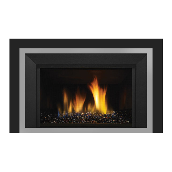
LRI6E / HRI6E Gas Insert
MODELS: LRI6E-NG Natural Gas
HRI6E-NG Natural Gas
WARNING
FIRE OR EXPLOSION HAZARD
Failure to follow safety warnings exactly could result in serious
injury, death, or property damage.
- Do not store or use gasoline or other flammable vapors and liquids in the vicinity of this or any other
appliance.
- WHAT TO DO IF YOU SMELL GAS
•
Do not try to light any appliance.
• Do not touch any electrical switch: do not use any phone in your building.
Leave the building immediately.
• Immediately call your gas supplier from a neighbour's phone. Follow the gas supplier's
instructions.
• If you cannot reach you gas supplier, call the fire department.
- Installation and service must be performed by a qualified installer, service agency or the gas supplier.
Tested by:
Installer: Please complete the details on the back cover
and leave this manual with the homeowner.
Homeowner: Please keep these instructions for future reference.
919-382a
LRI6E-LP Propane
HRI6E-LP Propane
FPI FIREPLACE PRODUCTS INTERNATIONAL LTD. 6988 Venture St., Delta, BC Canada, V4G 1H4
Owners &
Installation Manual
www.regency-fire.com
07.14.15
Advertisement
Table of Contents

Related Manuals for Regency LRI6E-NG


Summary of Contents for Regency LRI6E-NG
- Page 1 Owners & LRI6E / HRI6E Gas Insert Installation Manual www.regency-fire.com MODELS: LRI6E-NG Natural Gas LRI6E-LP Propane HRI6E-NG Natural Gas HRI6E-LP Propane WARNING FIRE OR EXPLOSION HAZARD Failure to follow safety warnings exactly could result in serious injury, death, or property damage.
- Page 2 Congratulations! You are the owner of a state-of-the-art Gas Insert by Regency. The Regency Gas Insert Series of hand crafted appliances has been designed to provide you with all the warmth and charm of a fireplace, at the flick of a switch. The models LRI6E / HRI6E of this series have been approved by Warnock Hersey for both safety and efficiency.
-
Page 3: Table Of Contents
table of contents Unit Dimensions ............4 3 Sided Low Profile Faceplate With Safety Unit Dimensions ............5 Screen Installation ............33 Ma Code - Co Detector..........9 4 Sided Faceplate With Safety Screen Installation..34 Important Message ............10 Spacer Installation ............35 Before You Start ............10 Backing Plate Installation ..........36 For Your Safety ............ -
Page 4: Unit Dimensions
dimensions UNIT DIMENSIONS Dimensions with Vignette Faceplate Dimensions with Vignette Faceplate and Backing Plate LRI6E / HRI6E Direct Vent Gas Insert... -
Page 5: Unit Dimensions
dimensions UNIT DIMENSIONS Dimensions with Vignette Faceplate and Spacer Dimensions with Vignette Faceplate-Spacer and Backing Plate LRI6E / HRI6E Direct Vent Gas Insert... - Page 6 dimensions Unit Dimensions for 4 Sided Vignette Faceplate Unit Dimensions with Low Profile Faceplate LRI6E / HRI6E Direct Vent Gas Insert...
- Page 7 This is a copy of the labels that accompany each LRI6E Gas Insert. We have printed a copy of the contents here for your review. NOTE: Regency units are constantly being improved. Check the label on the unit and if there is a difference, the label on the unit is the correct one.
-
Page 8: Safety Decal
This is a copy of the labels that accompany each HRI6E Gas Insert. We have printed a copy of the contents here for your review. NOTE: Regency units are constantly being improved. Check the label on the unit and if there is a difference, the label on the unit is the correct one. -
Page 9: Ma Code - Co Detector
requirements MA Code - CO Detector (for the State of Massachusetts only) 5.08: Modifications to NFPA-54, Chapter 10 (2) Revise 10.8.3 by adding the following additional requirements: (a) For all side wall horizontally vented gas fueled equipment installed in every dwelling, building or structure used in whole or in part for residential purposes, including those owned or operated by the Commonwealth and where the side wall exhaust vent termination is less than seven (7) feet above finished grade in the area of the venting, including but not limited to decks and porches, the following requirements shall be satisfied:... -
Page 10: Important Message
CAN/CGA B149 (in Canada) or the National AND OTHERS MAY BE SUSCEPTIBLE Fuel Gas Code ANSI Z223.1 in the U.S.A. This The Regency Gas Insert must be installed in TO ACCIDENTAL CONTACT BURNS. A appliance should be installed by a qualified gas accordance with these instructions. -
Page 11: For Your Safety
installation FOR YOUR SAFETY GAS PRESSURE TESTING This appliance requires air for proper combustion. Always provide adequate combustion and The appliance must be isolated from the gas sup- ventilation air. Follow instructions and information ply piping system by closing its individual manual in CAN/CGA B149 (in Canada) or the National Fuel shut off valve during any pressure testing of the Gas Code ANSI Z223.1 (in the USA), regarding... -
Page 12: Installation Checklist
MINIMUM FIREPLACE DIMENSIONS sections "Minimum Fireplace Dimensions and Clearances to Combustibles) The minimum fireplace clearances & dimensions for the Regency gas insert are shown in the following 2) Make the gas connection. (Refer to section "Gas diagrams: Connection") Gas connection is on the left side of the appliance. -
Page 13: Minimum Clearances To Combustibles
Min. Hearth requirements - An R value of 1.75 is required to meet the requirements of the hearth in front of this appliance. 1" of Calcium Silicate board available from Regency, part number (296-936) plus 3/8" tile or equivalent would meet this requirement. -
Page 14: Gas Connection
installation GAS CONNECTION The Air Intake and exhaust pipes must be attached to the inlet and exhaust collars of the termination cap with a minimum of three screws per pipe. GAS CONNECTION WARNING: Only persons licensed to work Part # Description with gas piping may make the 948-305... -
Page 15: Flue / Vent Installation
installation FLUE / VENT INSTALLATION 4) Use the Flue Connector Slide Tool to slowly pull the Flue Connector NOTE: Flue Plate Connector Gasket Intake Liner Plate forward as you move the Insert rearward into the Fireplace Chase. must not be damaged or removed. Exhaust Liner Care must be taken to ensure that this Gear Clamps... -
Page 16: Levelling Leg Adjustment
installation LEVELLING LEG ADJUSTMENT The LRI6E / HRI6E inserts are equipped with 2 rear levelling legs that are accessible while the appliance is in its final installation position. The unit can be adjusted up to 5/16" (16mm). Remove left and right side filler pieces. The rear levelling bolts are located in the back corners of the firebox and can be adjusted using a 7/16" wrench. Rotate the bolts clockwise to raise the rear of the firebox. -
Page 17: Air Shutter Adjustment
NOT covered under warranty. Push to close - Pull to open Note: Aeration Adjustment should only be performed by an authorized Regency Installer at the time of installation or service. | 17 LRI6E / HRI6E Direct Vent Gas Insert... -
Page 18: High Elevation
885 S.I.T. VALVE LRI6E-NG / HRI6E-NG Burner SYSTEM DATA DESCRIPTION Min. Supply Pressure 5" WC (1.25 kpa) Flame Sensor Manifold Pressure 3.5" WC (0.87 kpa) 1) 6 Stage flame adjustment 2) Pilot adjustment Orifice Size #32 DMS 3) Outlet Pressure Tap... -
Page 19: Conversion From Ng To Lp
installation L540E / HZI540E CONVERSION FROM NG TO LP CONVERSION FROM NG TO LP LRI6E/HRI6E using SIT 885 NOVA Gas Valve L540E/HZI540E using SIT 885 NOVA Gas Valve THIS CONVERSION MUST BE DONE BY A QUALIFIED GAS FITTER IF IN DOUBT DO NOT DO THIS CONVERSION! WARNING This conversion kit shall be installed by a qualifi... - Page 20 L540E / HZI540E installation 6) Ensure the rubber gasket, which is prefi tted as part of the Assembly, 11) Unscrew the pilot orifi ce with the allen key; then replace with the LPG is properly positioned. Install the new Pressure Regulator using the 2x pilot orifi...
-
Page 21: Proflame Remote System Gtmf With Fan
installation PROFLAME REMOTE SYSTEM GTMF WITH FAN (LRI6E / HRI6E) WIRING DIAGRAM Proflame System Configuration 886 GTMF Wire Diagram SureFire™ Switch 0.584.907 Ground Black Neutral Green Live Fan Thermodisc Ground 120V AC 60 Hz (normally open) Black Black Black GTMF REMOTE SYSTEM - IMPORTANT: The 120V fan control module serves as the power source for this unit. The AA batteries in the receiver only serve as a backup in case 120 volt power lost within the home. -
Page 22: Glass Crystal / Optional Stone Installation
installation GLASS CRYSTAL / OPTIONAL STONE INSTALLATION Spread the Glass Crystals or Stones evenly over the burner. Ensure the crystals/stones do not overlap excessively as this will affect the flame pattern. IMPORTANT NOTE: Only the supplied approved Glass Crystals and Stones are to be used with these fireplaces. Use of any other type of glass crystals or stones can alter the unit's performance, any damage caused by the use of any unapproved glass or stones will not be covered under warranty. - Page 23 HZI540EB ADDENDUM installation CAUTION DO NOT place spa stones or volcanic stones over pilot and burner ports. No spa stones in this area. No volcanic stones in this area. | 23 LRI6E / HRI6E Direct Vent Gas Insert 09/28/11...
-
Page 24: Hri6E Optional Log Set Installation
HRI6E / HRI4E installation HRI6E OPTIONAL LOG SET INSTALLATION OPTIONAL LOG SET INSTALLATION Read the instructions below carefully and refer to the images. If the logs are broken do not use the unit until they are replaced. Broken logs can interfere with pilot operation. Improper positioning of the logs may create carbon build-up and can alter the unit's performance which is not covered under warranty. - Page 25 HRI6E / HRI4E installation 8. Place Log 6 - rest on Log 3 as shown below. 5. Place Log 3, rest on Log 2, match pin locator on Log 2 with landing pin on Log 1. Angle the longest point on Log 3 is approximately 1/4' from the outside edge of the burner tray.
-
Page 26: Lri6E Log Set Installation
installation LRI6E LRI6E LOG SET INSTALLATION LOG INSTALLATION Read the instructions below carefully and refer to the images. If the logs are broken do not use the unit until they are replaced. Broken logs can interfere with pilot operation. Improper positioning of the logs may create carbon build-up and can alter the unit's performance which is not covered under warranty. *For Touch Ups: Satin Black paint is included for burner, and Dark Brown Paint is included for log set, Rear Centre Log Left Side Log... - Page 27 LRI6E installation LOG INSTALLATION 6. Place Log 4 on the burner in the location shown below. 8. Line locator at top of Log 6 with provision on Log 1 - the locator at the bottom of Log 6 should line up with the provision on Log 5. 7.
-
Page 28: Standing Pilot And Heat Exchange Return
installation STANDING PILOT AND HEAT EXCHANGE RETURN ADDING THE HEAT EXCHANGER RETURN The LRI6E / HRI6E use a heat exchanger and efficient combustion technol- ogy to provide extreme heating efficiencies. The more efficient an appliance 1) Remove the panels if they are already installed. Remove one screw becomes, the lower the flue gas temperatures becomes. -
Page 29: Brick Panel Installation
installation L540E/ L540PB BRICK PANEL INSTALLATION BRICK PANEL INSTALLATION Brick panels are soft and fragile. Use caution when handling the panels, xha st aff e being careful not to jar them or scratch the painted surfaces. Firebox Liner Rear Firebox Liner Right Firebox Liner Left Firebox Liner Left er Le... -
Page 30: Enamel Panel Installation
HrI6E / HrI4E installation EnamEl panEl InstallatIon ENAMEL PANEL INSTALLATION 1) Remove filler sections from right and left sides of the burner and discard Before you start: - see below. Black Enamel panels • Black Enamel panels must be inspected for scratches and dimples prior to installation. -
Page 31: Glass Door Removal / Installation
installation GLASS DOOR REMOVAL / INSTALLATION WARNING: Do not operate the appliance with the glass panels removed, cracked or broken. Replacement of the glass panels should be done by a licensed or qualified service person. 1) Insert the door tool into the lower door latch. Window Clip (x4) Door Frame Glass Gasket Retainer... -
Page 32: Vignette Faceplate With Safety Screen Installation
VIGNETTE FACEPLATE installation VIGNETTE FACEPLATE W/SAFETY SCREEN INSTALLATION VIGNETTE FACEPLATE WITH SAFETY SCREEN INSTALLATION Black Chrome Handling Instructions All hand and fi nger marks MUST be cleaned off with a soft cloth. Use an ammonia based cleaner (ie. glass cleaner) to remove any fi... -
Page 33: Sided Low Profile Faceplate With Safety Screen Installation
LRI4E / HRI4E / LRI6E / HRI6E installation 3 SIDED LOW PROFILE FACEPLATE WITH SAFETY SCREEN INSTALLATION 3 SIDED LOW PROFILE FACEPLATE W/SAFETY SCREEN INSTALLATION Note: A mantel deflector may be installed to reduce the minimum mantel height. 4. Install front faceplate by hooking back of front faceplate over lip edge on Refer to minimum clearances in the installation manual. -
Page 34: Sided Faceplate With Safety Screen Installation
installation 4 SIDED FACEPLATE WITH SAFETY SCREEN INSTALLATION 1. Install the outer faceplate and secure with 6 screws as shown. 2. Install the outer faceplate by hooking the flange over the hanger as shown. 34 | LRI6E / HRI6E Direct Vent Gas Insert... -
Page 35: Spacer Installation
installation SPACER INSTALLATION SPACER INSTALLATION The installation of a spacer may be required to maintain the fl ush appearance of the faceplate. 1. Secure outer faceplate to spacer trim using 4 screws. 2. Install the outer faceplate with spacer trim and secure with 6 screws as shown. Route power cord through the inner and outer rear profi... -
Page 36: Backing Plate Installation
installation BACKING PLATE INSTALLATION BACKING PLATE INSTALLATION Backing Plate Installation Backing Plate Installation without Spacer with Spacer 1. Secure backing plate to spacer trim with 7 screws in the locations 1. Secure the backing plate to the outer faceplate and secure with 7 shown below. -
Page 37: Optional Mantel Deflector Installation
MANTEL DEFLECTOR INSTALLATION installation OPTIONAL MANTEL DEFLECTOR INSTALLATION Low Profile Faceplate LRI4E/HRI4E Onl Vignette Faceplate Note: A mantel deflector may be installed to reduce the minimum mantel Note: A mantel deflector may be installed to reduce the minimum mantel height. height. - Page 38 LRI4E/HRI4E/LRI6E/HRI6E/E33 operating instructions OPTIONAL HEARTH TRIM INSTALLATION -VIGNETTE FACEPLATE WITH SPACER AND LOW PROFILE FACEPLATE 5) Secure the hearth trim with a clip on its side to keep it steady as shown in Customizing the Hearth Trim: the picture below . The Hearth Trim can be adjusted to custom fit an installation by pulling apart the top piece from the bottom piece.
-
Page 39: Operating Instructions
operating instructions LRI4E/HRI4E/LRI6E/HRI6E/E33 OPERATING INSTRUCTIONS OPTIONAL HEARTH TRIM Before operating this appliance, proceed through the following check list. INSTALLATION - VIGNETTE 1) Read and understand these Instructions before operating this appliance. FACEPLATE WITHOUT SPACER 2) Check to see that all wiring is correct and enclosed to prevent possible shock. Customizing the Hearth Trim The Hearth Trim can be adjusted to custom fit an installation by pulling 3) Check to ensure there are no gas leaks. -
Page 40: Lighting Procedure
operating instructions LIGHTING PROCEDURE IMPORTANT: The remote control system supplied with this appliance has several options for starting/operating the appliance using the power button 3. After approximately 4 seconds the spark ignition system will spark for 60 and ON/OFF key on the hand held transmitter. seconds to light the main burner. -
Page 41: Copy Of Lighting Instruction Plate
Reportez-vous au manuel du propriétaire de l'information fournie avec cet appareil. Pour obtenir de l'aide ou des informations supplémen- Regency gas appliances use high tech blowers taires consulter un installateur qualifi é, une agence de service ou fournisseur de gaz. -
Page 42: Maintenance Instructions
GUARD REMOVED FOR SERVICING AN and louvers with a damp cloth. Never use an Regency dealer only, and follow our step-by-step APPLIANCE MUST BE REPLACED PRIOR abrasive cleaner. The gold louvers (and optional instructions for replacement. -
Page 43: Pilot Adjustment
Continuous condensation can cause corrosion Note: If you have an incorrect flame pattern, of caps, pipe, and fittings. It may be caused contact your Regency dealer for further ® by having excessive lateral runs, too many instructions. -
Page 44: Glass Crystal Burner Removal / Installation (Hri6E)
maintenance GLASS CRYSTAL BURNER REMOVAL / INSTALLATION (HRI6E) GLASS BURNER INSTALL Disconnect unit from gas supply and allow unit to cool before removing burner. GLASS BURNER REMOVAL 1) Lift the burner assembly with both hands. Point the mixing tube towards the rear of the firebox. -
Page 45: Lri6E Ceramic Burner Removal / Installation
maintenance LRI6E CERAMIC BURNER REMOVAL / INSTALLATION INSTALLATION REMOVAL 1) Remove left and right side panels by sliding them forward - see below. Care must be taken when installing the burner into the firebox. Do not damage, knock or scrape the pilot assembly. The flame sensor and ignition lead are fragile and can be damaged easily. -
Page 46: Fan Maintenance - With Gtmf Remote Control
maintenance FAN MAINTENANCE - WITH GTMF REMOTE CONTROL Note: To access the side and rear access panels both the gas and venting 4) Remove 3 screws and remove the fan from the unit as shown below. will need to be disconnected(see vent/flue installation in this manual) for proper removal. -
Page 47: Valve Replacement
maintenance VALVE REPLACEMENT Before you begin: 5) Disconnect the Pilot Supply Line from the Gas Valve * Shut off the gas supply to the unit. Disconnect all electrical supply to the unit. Always let the appliance cool to room temperature before servicing. Remove unit flue collars. - Page 48 maintenance 11) There is a provision in the Valve body casting that is designed to be 8) Remove the Gas Valve by lifting upwards and outwards. used as a gripping point for assembly with other components. This is the portion of the valve that can be placed in a machine vice. 9) Secure the Valve Assembly by the 90 Elbow Fitting in a sturdy table vice.
-
Page 49: Main Assembly
parts list MAIN ASSEMBLY Part # Description Part # Description 940-372/P Window Glass 396-031 Bracket Valve Mounting Lh/Rh 911-085 Valve LP 885 SIT IPI 0.885.002 936-159 Window Gasket (per ft. - 9ft. required) 911-084 Valve NG 885 SIT IPI 0.885.002 396-042f Slide / Door Tool 396-574/P... -
Page 50: Parts List
parts list 50 | LRI6E / HRI6E Direct Vent Gas Insert... -
Page 51: Warranty
parts list Part # Description Part # Description 299-957 Backing Plate Accent Trim 299-918 Vignette Door Inlay Black Chrome 299-958 Backing Plate Accent Trim - Custom 299-919 Vignette Door Inlay Metallic Black 299-956 Spacer Accent - Black 299-920 Vignette Door Inlay Tuscan Sunset 299-914 Accent trim - Metallic black (2 piece) 299-922... - Page 52 notes 52 | LRI6E / HRI6E Direct Vent Gas Insert...
- Page 53 notes | 53 LRI6E / HRI6E Direct Vent Gas Insert...
- Page 54 notes 54 | LRI6E / HRI6E Direct Vent Gas Insert...
- Page 55 It is the general practice of FPI to charge for larger, higher priced replacement parts and issue credit once the replaced component has been returned to FPI and evaluated for manufac- turer defect. The authorized selling dealer is responsible for all in-field service work carried out on your Regency product. FPI will not be liable for results or costs of workmanship from unauthorized service persons or dealers.
- Page 56 Phone #: ___________________________________________________________ Date Installed: ______________________________________________________ Serial No.: __________________________________________________________ HZI540 Product Video LRI6E Product Video Regency and Regency Horizon, are trademarks of FPI Fireplace Products International Ltd. ® Printed in Canada © Copyright 2015, FPI Fireplace Products International Ltd. All rights reserved.