Regency LRI4E Owners & Installation Manual
Gas insert
Hide thumbs
Also See for LRI4E:
- Owners & installation manual (56 pages) ,
- Owners & installation manual (72 pages)
Table of Contents
Advertisement
LRI4E / HRI4E Gas Insert
MODELS: LRI4E-NG Natural Gas
HRI4E-NG Natural Gas
WARNING
FIRE OR EXPLOSION HAZARD
Failure to follow safety warnings exactly could result in serious
injury, death, or property damage.
- Do not store or use gasoline or other flammable vapors and liquids in the vicinity of this or any other
appliance.
- WHAT TO DO IF YOU SMELL GAS
•
Do not try to light any appliance.
• Do not touch any electrical switch: do not use any phone in your building.
Leave the building immediately.
• Immediately call your gas supplier from a neighbour's phone. Follow the gas supplier's
instructions.
• If you cannot reach you gas supplier, call the fire department.
- Installation and service must be performed by a qualified installer, service agency or the gas supplier.
Tested by:
919-380
LRI4E-LP Propane
HRI4E-LP Propane
Installer: Please complete the details on the back cover
and leave this manual with the homeowner.
Homeowner: Please keep these instructions for future reference.
FPI FIREPLACE PRODUCTS INTERNATIONAL LTD. 6988 Venture St., Delta, BC Canada, V4G 1H4
Owners &
Installation Manual
Liberty LRI4E
Horizon HRI4E
www.regency-fire.com
09.24.14
Advertisement
Table of Contents

Related Manuals for Regency LRI4E


Summary of Contents for Regency LRI4E
- Page 1 Owners & LRI4E / HRI4E Gas Insert Installation Manual Liberty LRI4E Horizon HRI4E www.regency-fire.com MODELS: LRI4E-NG Natural Gas LRI4E-LP Propane HRI4E-NG Natural Gas HRI4E-LP Propane WARNING FIRE OR EXPLOSION HAZARD Failure to follow safety warnings exactly could result in serious injury, death, or property damage.
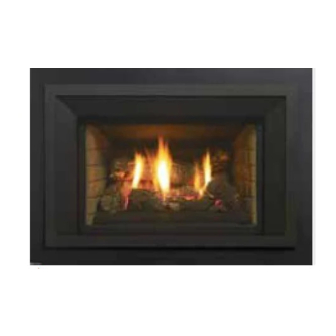
- Page 2 The Regency Gas Insert Series of hand crafted appliances has been designed to provide you with all the warmth and charm of a fireplace, at the flick of a switch. The models LRI4E / HRI4E of this series have been approved by Warnock Hersey for both safety and efficiency.
-
Page 3: Table Of Contents
Gas Pipe Pressure Testing ..........17 General Vent Maintenance ..........42 885 S.I.T. Valve Description .........17 Log Replacement ............42 Proflame remote system GTMF with fan (LRI4E / Glass Gasket ...............42 HRI4E) .................18 Glass crystal burner removal / installation - HRI4E ..43 Conversion from NG to LP ........19 Glass Burner Removal ..........43... -
Page 4: Unit Dimensions With Vignette Faceplate
UNIT DIMENSIONS WITH VIGNETTE FACEPLATE LRI4E / HRI4E Direct Vent Gas Insert... -
Page 5: Unit Dimensions With Low Profile Faceplate
UNIT DIMENSIONS WITH LOW PROFILE FACEPLATE LRI4E / HRI4E Direct Vent Gas Insert... -
Page 6: Safety Decal
NOTE: Regency units are constantly being improved. Check the This is a copy of the labels that accompany each LRI4E Gas Insert. We have printed a copy of the contents here for your review. label on the unit and if there is a difference, the label on the unit is the correct one. - Page 7 NOTE: Regency units are constantly being improved. Check the This is a copy of the labels that accompany each HRI4E Gas Insert. We have printed a copy of the contents here for your review. label on the unit and if there is a difference, the label on the unit is the correct one.
-
Page 8: Ma Code - Co Detector
(e) A copy of all installation instructions for all Product Approved side wall horizontally vented gas fueled equipm ent, all venting instructions, all parts lists for venting instructions, and/or all venting design instructions shall remain with the appliance or equipment at the completion of the installation. LRI4E / HRI4E Direct Vent Gas Insert... -
Page 9: Important Message
IN THE SAME AREA AS THE APPLI- ANCE. TODDLERS, YOUNG CHILDREN AND OTHERS MAY BE SUSCEPTIBLE The LRI4E / HRI4E Gas Inserts must be installed in TO ACCIDENTAL CONTACT BURNS. A accordance with these instructions. Carefully read PHYSICAL BARRIERS IS RECOMMEND- all the instructions in this manual first. -
Page 10: Important Message
4) See general construction and assembly instructions. This appliance may only be This appliance requires air for proper combustion. The LRI4E / HRI4E Gas Inserts have been tested installed in a vented, noncombustible fireplace. and approved to be vented into any masonry... -
Page 11: Installation Checklist
DIMENSIONS Clearances to Combustibles) 2) Make the gas connection. (Refer to section "Gas The minimum fireplace clearances & dimensions for the Regency gas insert are shown in the following Connection") diagrams: 3) Install the two 3" flue liners (intake and exhaust) to the sliding connector plate. -
Page 12: Minimum Clearances To Combustibles
Note: All material used must be completely non-combustible. 12 | LRI4E / HRI4E Direct Vent Gas Insert... -
Page 13: Gas Connection
Periodically check that the vent is unrestricted. Masonry chimneys may take various contours which the flexible liner will accommodate. However, keep the flexible liner as straight as possible, avoid Gas & Electrical Connections unnecessary bending. LRI4E / HRI4E Direct Vent Gas Insert... -
Page 14: Flue / Vent Installation
Plate Gasket WARNING: Failure to position the parts in accordance with these diagrams or failure to use only parts specifically approved with this appliance may result in property damage or personal injury. 14 | LRI4E / HRI4E Direct Vent Gas Insert... -
Page 15: Levelling Leg Adjustment
LEVELLING LEG ADJUSTMENT The LRI4E / HRI4E inserts are equipped with 2 rear levelling legs that are accessible while the appliance is in its final installation position. The unit can be adjusted up to 5/16" (16mm). Remove left and right side filler pieces. The rear levelling bolts are located in the back corners of the firebox and can be adjusted using a 7/16" wrench. -
Page 16: Air Shutter Adjustment
The LRI4E / HRI4E is equipped with an air shutter that is accessible from outside the firebox and can be adjusted during operation. -
Page 17: High Elevation
6) When finished reading manometer, turn off the gas valve, disconnect the hose and tighten the screw (clockwise) with a 1/8" flat screwdriver. Note: Screw should be snug, but do not over tighten. LRI4E / HRI4E Direct Vent Gas Insert... -
Page 18: Proflame Remote System Gtmf With Fan (Lri4E / Hri4E)
PROFLAME REMOTE SYSTEM GTMF WITH FAN (LRI4E / HRI4E) Proflame System Configuration 886 GTMF Wire Diagram Proflame Remote Operation Proflame Remote Battery Change GTMF REMOTE SYSTEM - IMPORTANT: The 120V fan control module serves as the power source for this unit. The AA batteries in the receiver only serve as a backup in case 120 volt power lost within the home. -
Page 19: Conversion From Ng To Lp
M4 x .7 screws supplied. Tighten the screws to 25lb-in. In the event that the screw threads are cross threaded or stripped, replace the valve The valve in the LRI4E is attached using 2 screws and 2 hooks located assembly. - Page 20 13) Adjust aerations settings - see Air Shutter Adjustment section in the manual. Installer Notice: These instructions must be left with the appliance Pilot retainer clip 20 | LRI4E / HRI4E Direct Vent Gas Insert 919-409 07/07/14...
-
Page 21: Glass Crystal / Ceramic Spa Stone Installation
Natural River Pebbles shown surrounding the a Horizon Burner Glass Crystals shown surrounding the Burner Glass Crystals shown on Burner and Firebox Floor For Units HZI390E, HZI540E DO NOT block pilot area with glass crystals LRI4E / HRI4E Direct Vent Gas Insert... - Page 22 HZI390E ADDENDUM CAUTION DO NOT place spa stones over pilot and burner ports. No spa stones in this area. 22 | LRI4E / HRI4E Direct Vent Gas Insert...
-
Page 23: Hri4E Optional Log Set Installation
Sweep glass aside (if already installed) to install Rear Log Bracket, clip the front edge of the rear bracket on to rear of the burner as shown below. 9-1/4" Position Log 2 Rear Log Bracket LRI4E / HRI4E Direct Vent Gas Insert 07/30/14 919-350a... - Page 24 12. Adjust aeration setting to fully open (manual for detailed instruc- HRI4E Pin Landing tions) Note: Logs to be installed in NG units only. Line up pin locator and pin, Logs 5,4 24 | LRI4E / HRI4E Direct Vent Gas Insert 919-350a 07/30/14...
-
Page 25: Lri4E Log Set Installation
2. Identify corresponding pin locators on bottom of Log 2 and line up indent. to prevent any carboning. with pins on burner- see below. Log 3 push to the back of the indent Log 2 pin locator, line up with pins on burner 919-408 07.03.14 LRI4E / HRI4E Direct Vent Gas Insert... - Page 26 Location for Log 5 7. Log 6 is positioned in the indent on the far right of the burner in the orientation shown below. Final Install Location for Log 6 26 | LRI4E / HRI4E Direct Vent Gas Insert 919-408 07.03.14...
-
Page 27: Standing Pilot
STANDING PILOT The LRI4E / HRI4E use a heat exchanger and efficient combustion technol- ogy to provide extreme heating efficiencies. The more efficient an appliance ADDING THE HEAT EXCHANGER RETURN becomes, the lower the flue gas temperatures becomes. On start-up, flue temperatures are required to initiate venting action. -
Page 28: Brick Panel Installation
Liner Rear. The side Liner will hold the rear Liner in place. Install the Fire- box Liner Left the same way you installed the Firebox Liner Right. Both side liners should be just slightly back from the front edge of the Firebox. Brick Panel Installation 28 | LRI4E / HRI4E Direct Vent Gas Insert... -
Page 29: Enamel Panel Installation
You may have to push the liner against the firebox as you push it rearward. Panel retainers Installing Enamel Panels HRI6E *Insulation panels not shown in this diagram LRI4E / HRI4E Direct Vent Gas Insert 07/30/14 919-025c... -
Page 30: Glass Door Removal / Installation
6) Pull the bottom of the door towards you until the door is angled away from the firebox by about 30°. Lift the door up and over the upper door hooks. 7) To install the glass door - reverse steps. Glass Door Cleaning & Removal 30 | LRI4E / HRI4E Direct Vent Gas Insert... -
Page 31: Vignette Faceplate With Mesh Barrier Installation
NOTE: Pull the bottom of the Vignette faceplate towards you to access the remote receiver located at the lower left corner. Power Cord Location 2. Install the Vignette faceplate by hooking the fl ange over the hanger as shown. LRI4E / HRI4E Direct Vent Gas Insert 09.19.14 919-417... -
Page 32: Sided Low Profile Faceplate With Mesh Barrier Installation
/ HRI4e / lRI6e / HRI6e 3 SIDED LOW PROFILE FACEPLATE WITH MESH BARRIER INSTALLATION 3 sIded low pRofIle faceplate w/mesH baRRIeR InstallatIon note: A mantel deflector may be installed to reduce the minimum mantel height. 5. Install front faceplate by hooking back of front faceplate over lip edge on Refer to minimum clearances in the installation manual. -
Page 33: Sided Faceplate With Mesh Barrier Installation
4 SIDED FACEPLATE WITH MESH BARRIER INSTALLATION 1. Install the outer faceplate and secure with 6 screws as shown. 2. Install the outer faceplate by hooking the flange over the hanger as shown. LRI4E / HRI4E Direct Vent Gas Insert... -
Page 34: Spacer Installation
3. Line up the notch in the center of the spacer accent trim assembly with the protruding screw installed in Step 2. NOTE: To access remote receiver pull the bottom of the faceplate towards you. It is located in the bottom left corner. 34 | LRI4E / HRI4E Direct Vent Gas Insert... -
Page 35: Backing Plate Installation
7 screws in locations shown below. Painted side of backing plate faces spacer accent trim. NOTE: To access remote receiver pull the bottom of the faceplate towards you. It is located in the bottom left corner. LRI4E / HRI4E Direct Vent Gas Insert 09.23.14 919-419... -
Page 36: Optional Mantel Deflector Installation
2. Bend all 3 tabs up to secure the defl ector to the top of the backing plate. Top of backing plate Note: Faceplate may be installed after the unit is in its fi nal position. Installed mantel defl ector 36 | LRI4E / HRI4E Direct Vent Gas Insert 919-421 09.22.14... -
Page 37: Optional Hearth Trim Installation
1. Line up Hearth Trim with base of unit and secure with 3 screws as shown below. Vignette Faceplate shown 09.16. 919-397 optional hearth trim installation 1. Line up Hearth Trim with base of unit and secure with 3 screws as shown below. LRI4E / HRI4E Direct Vent Gas Insert... -
Page 38: Operating Instructions
After the unit has been turned off and the unit cooled to below a useful heat output range the fan will shut off automatically. Glass Door Cleaning & Removal 38 | LRI4E / HRI4E Direct Vent Gas Insert... -
Page 39: Lighting Procedure
(see Diagram 2). An audible beep should be heard from the receiver. 3. Turn the gas control knob to the "OFF" position to turn off the pilot. ON/OFF Button Diagram 2 Remote shown in Manual Mode on Hi LRI4E / HRI4E Direct Vent Gas Insert... -
Page 40: Normal Operating Sounds Of Gas Appliances
Utilisez l'interrupteur murale ON/OFF du Brûleur ou du contrôle à distance pour éteindre le brûleur. Appuyez sur OFF sur la télécommande. Mettre le bouton de commande de gaz en position OFF pour éteindre la veilleuse. DO NOT REMOVE THIS INSTRUCTION PLATE 919-401 40 | LRI4E / HRI4E Direct Vent Gas Insert... -
Page 41: Maintenance Instructions
1 flow- ing around the thermopile and 1 around the thermocouple, and 1 flowing across the rear of the burner (it does not have to be touching the burner). Window Glass Door Components LRI4E / HRI4E Direct Vent Gas Insert... -
Page 42: Pilot Adjustment
GLASS GASKET If the glass gasket requires replacement use glass gasket for the Flush Front (Part # 936-112). 42 | LRI4E / HRI4E Direct Vent Gas Insert... -
Page 43: Glass Crystal Burner Removal / Installation - Hri4E
** Do not to install glass or other media over or in front of the Pilot Provision as shown. Important: Do not to install glass or other media in this area, as this will black the path of the pilot to the burner. LRI4E / HRI4E Direct Vent Gas Insert... -
Page 44: Lri4E Ceramic Burner Removal / Installation
Ceramic Burner and the firebox Bottom Flange. The Burner should be situated about ¼” (6mm) inside the front edge of the firebox. 4) To install - reverse Steps 3-2, see Step 1 for correct installation tips. 44 | LRI4E / HRI4E Direct Vent Gas Insert... -
Page 45: Fan Maintenance - With Gtmf Remote Control
1/4" spade connectors to the fan terminals. Disconnect the ground lug to the fan using the screw provided. Strain Relief Power Cord Fan Controller Wire Retainer Fan Wire Harness Fan Terminals Ground Wire Fan Mounting Bracket Diagram 2 LRI4E / HRI4E Direct Vent Gas Insert... -
Page 46: Valve Replacement
3) Disconnect the Pressure Regulator cable. 7) Remove both Screws that secure the Gas Valve Mounting brackets, both sides. Pressure regulator cable 4) Disconnect the Gas Orifice supply line from the outlet of the Gas Valve. 46 | LRI4E / HRI4E Direct Vent Gas Insert... - Page 47 15) Reconnect the gas and electrical supply to the unit. Once the unit has be re-fired, use a soapy water mixture to check all fittings and gas sup- ply lines for gas leaks. LRI4E / HRI4E Direct Vent Gas Insert...
-
Page 48: Parts List
911-012 Ignition board SIT IPI 911-137 Pilot Hood Holding Clip 910-572 SIT Proflame receiver Part Not Shown 911-074 Pilot Assy Ground Wire 396-043 Firebox Liner Retainers 396-114 Burner End - L 48 | LRI4E / HRI4E Direct Vent Gas Insert... - Page 49 LRI4E / HRI4E Direct Vent Gas Insert...
- Page 50 Oversize faceplate - Iron grey 399-926 4 sided faceplate (custom sizes) - Metallic black 399-914 Accent trim - Metallic Black 399-912 Accent trim - Platinum 399-913 Accent trim - Chrome 399-956 Spacer Accent - Black 50 | LRI4E / HRI4E Direct Vent Gas Insert...
-
Page 51: Warranty
It is the general practice of FPI to charge for larger, higher priced replacement parts and issue credit once the replaced component has been returned to FPI and evaluated for manufacturer defect. The authorized selling dealer is responsible for all in-fi eld service work carried out on your Regency product. FPI will not be liable for results or costs of workmanship from unauthorized service persons or dealers. - Page 52 Phone #: ___________________________________________________________ Date Installed: ______________________________________________________ Serial No.: __________________________________________________________ Liberty LRI4E Horizon HRI4E Regency and Regency Horizon, are trademarks of FPI Fireplace Products International Ltd. ® Printed in Canada © Copyright 2014, FPI Fireplace Products International Ltd. All rights reserved.