
Related Manuals for Invacare G40


Summary of Contents for Invacare G40
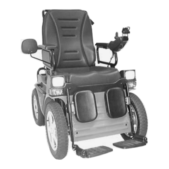
- Page 1 Invacare ® G40 with ACS-System S E R V I C E - M M A N U A L The manual contains: Information on troubleshooting Information on testing parts Repair instructions Edition: 12.2001...
- Page 2 Invacare Deutschland GmbH Postfach 60 01 06 D-32 527 Bad Oeynhausen • INVACARE can not be held liable for changes to the “G40” resulting from maintenance and servicing work carried out incorrectly or not according to the relevant instructions. Information concerning transportation •...
-
Page 3: Table Of Contents
Contents Safety and installation instructions ..4 10.0 Checks and repair work at List of tools ......5 power supply 10.1 Batteries, battery box and check of . -
Page 4: Safety And Installation Instructions
• Support the raised wheelchair with suitable supports before you begin assembly. Use the bottom tube . frames of the chassis. Also see the illustration G40, bottom view, chapter 6.0. • You should under no circumstances use “normal” nuts instead of self-locking nuts. -
Page 5: List Of Tools
Soldering iron 30W Assembly pliers for Starlock caps (commercially available) Removing tools for font wheel hub (available by INVACARE-Service) You will require the following for setting at the ACS control: Programming unit Item no. Software package, incl. interface cable and dongle... -
Page 6: Inspection Plan
3.0 Inspecton plan Component Check Action Chapter Armrests and sides • Damage to and attachment > Tighten screws. Repla- of armrests ce overlay. • Damage to and attach- > Tighten screws. Repla- ment of side panels ce sides. • Mirrors >... - Page 7 Component Check Action Chapter Batteries • Damage of battery and > Clean contacts, replace box, corrosion on battery or box 10.1 contacts 10.2 • Check of contacts and > Tighten, replace. pole clips • Check battery voltage > Charge battery, replace. Light-servo module •...
-
Page 8: Operation Troubles
4.0 Operation troubles 4.1 General instructions Do the following if there are any troubles in driving mode, at lighting system or power supply: • Analyze the in 4.2 described troubleshooting. • Check the status display at remote and analyze the error codes like in chapter 5.1. •... - Page 9 Steering servo motor reacts slowly / irregularly Chapter 9.1 Motor defective Replace motor Manual for pro- Incorrect program- Check program- gramming unit or ming ming PCD-software Light-/servo modu- Replace light- Chapter 12.3 le defective /servo module Status display flashes, after 4 sec. the driving mode display also flashes Joystick not in Switch remote off...
-
Page 10: Error Messages At Remote
5.0 Error messages at remote 5.1 Error codes of remote The following error codes refer to the G40 standard model with remote, main module and servo-/light module. Do the follwing check before analyzing the error codes: • Switch on and off the remote several times. - Page 11 Check modules and Programming, Chapter 14.0 ween the modules inform INVACARE-service 10 x flashes Power-assisted steering- or Switch off and on the remote 11 x flashes drive motor overloaded Compatibilityproblems bet- Repair by INVACARE-service 12 x flashes ween the modules necessary...
-
Page 12: Arrangement Of Assembly Groups, Components And Operation Elements
The following illustrations show the arrangement of the main assemblies, components and features for right- handed people. The terms are the same as the component terms in the replacement parts catalog. G40, front view Leg rests complete, appertaining to seat... - Page 13 G40, service view Chassis (Tube frame back, bottom) Seat frame, appertaining to seat system Seat shell with indentations for electronic modules Locking mechanism of seat support for service Locking mechanism of seat in closed position Gas spring for back rest adjusting...
-
Page 14: Checks And Repair Work At Seatsystem
7.0 Checks and repair work at seat system Arm rests and sides Right side, complete Left side, complete 12, 11 12, 11 Arm rest tube frame Arm rest Side covering Bag (not illustrated) Side mount Clip lever M8x60 Mirror Wing screw M6x10 Hexagon head screw M6x16 10 Nut M8, self locking with cap 11 Hexagon head screw M5x35... -
Page 15: Legrests
Legrests Legrests compl. Legrest Parts 15,16 Legrest, top Insertion tube Footplate mount Footplate Calfsupport holder Calfsupport Calf pad mount Calfsupport pivot 2 Plastic discs 17x6,5 10 Clamping lever M6x10 11 Hexagon head screw M6x10 12 Fillister-head screw M6x16 13 Countersunk screw M5x25 14 Nut M5 (self locking) 15 Screw M6x45 16 Nut M6... -
Page 16: Grip
Backrest with frame, padding and grip Backrest, front view, without padding Backrest, back view 11, 12 7, 8 3, 4, 5, 16 Back shell Backframe Backmount socket Starlock caps 16,0 Disc 17,0 Backpadding (not shown) Clutch part for gas spring Wing screw M6x10 Safety belt (not shown) 10 Mounting plate for safety belt... - Page 17 Assembly • Assembly is carried out in reverse order. NOTE: • Use new starlock caps (4) for assembly. • During assembly of backframe (2) take care, that the discs (5) are pushed into the backmount socket in right order. For assembly of backframe at chassis do the following: •...
-
Page 18: Backrestadjusting
Backrestadjusting Gas spring and bow- den wire compl. 6, 7 Gas spring Fork M10x1 Trip lever for gas spring Adjustment screw Clamping screw Bowden wire Bowden wire sleeve 6, 7 Backframe Clutch 10 Wing screw M6x10 11 Hexagon head screw M10x35 12 2 discs 10,5 13 Nut M10... -
Page 19: Seatframe, Seat Shell And Padding
Seatframe, seat shell and padding Seatframe Seat shell Light-/servo module Seatframe Seat shell Padding (not shown) Latching mechanism Front lighting equipment, compl. Connector row for lighting system Check Action • Padding damaged? > Replace padding. • Seat shell damaged? > Replace seat shell. •... -
Page 20: Checks And Repair Work At Chassis
8.0 Checks and repair work at chassis Chassiscovering, grips and cover coating Chassiscovering Side grip 9, 10, 11 9, 10, 11 Chassiscovering Side grip 3 Cover coating Rosettes Stick holderr 6 Plastic rivet Brake lever Wing screw M6x10 9 Cap SKS 8 10 Hexagon head screw 11 Securing disc Schnorr M8 Check... -
Page 21: Wheels And Tyres
Wheels and tyres Front wheel, NOTE: assembled • Back and front wheels are all fixed with four countersunk screws on the wheel hubs. • Construction of rims is equal. • Because of that the disassembly is identical. 1 Front wheel, compl. 7 Back wheel, compl. -
Page 22: Back-Wheel Suspension
Wheel suspension back NOTE: Wheel suspension back • Change or repair of steering column (4) must be 13, 15 done by INVACARE-service. Shock absorber, soft Stub axle floating socket Steering column in steering column Head screw M12x120 Nut M12 Disc 13,0... -
Page 23: Front.wheel Suspension
Wheel suspension front NOTE: • Change or repair of front axle (5), gear rocker arm (2) and all components appertaining to gear must 12, 13, 14 be done by INVACARE-service. Shock absorber, hard Gear rocker arm Wheel hub Brake disc 160x2 Front axle, compl.. -
Page 24: Handbrake
Handbrake Handbrake, diagram of bowden wires Chassis Wing screw Mx10 Brake lever Brake straps, riveted compl. Bowden wire holder Brake caliper Bowden wire Cable clamp screw Bowden wire sleeve Hexagon head screw M6x25 10 Brake shoes 11 Fixing screw 12 Mounting 13 Hexagon head screw M6x35 14 Brake disc Brake disc,... - Page 25 Disassembly Brake disc • Disassemble front wheel. See also chapter 8.2. • Remove brake caliper (5) from mounting (12). See above. • Remove nut (18) and disc and take off wheel hub (19) with brake disc from axle. • Release four countersunk screws (M6 with hexagon) and take off brake disc (14) from hub. Assembly NOTE: •...
-
Page 26: Checks And Repair Work At Motor, Gears, Servo And Steering
9.0 Checks and repair work at motor, gear, servo and steering Driving motor and gear Driving motor Chassis Driving motor 450W Stopper with carbon brush Disengaging lever Gear, compl. Thread rod with square hinge Shock absorber Mounting Hexagon head screw. M5x20 10 Gear rocker arm 11 Hexagon head screw... - Page 27 • The driving unit can only be completely replaced. > Danger uf crushing< • Repairwork at driving unit must be done by INVACARE-service. • Bring seat system in service position and arrest. • Remove both motor plugs at main module and also plug connection at voltage supply.
-
Page 28: Power-Assisted Steering Unit
• Only basical checks can be done. unit. • The unit can only be completely replaced. • Repairwork at power-assisted steering unit must be • Steering bracket or done by INVACARE-service. > Replace defec- gear rocker arms tive parts. damaged? Disassembly of power-assisted steering unit, compl. -
Page 29: Battery Voltage
10.0 Checks and repair work at voltage supply 10.1 Check of batteries, battery box and batteryvoltage NOTE: • Secure that both batteries are loaded. If total voltage lies under 24 V, load batteries completely (see chapter 10.2). • Sinks batteryvoltage during operation under 24 V, the voltage supply to the motor is interrup ted and remote display flashes. -
Page 30: Battery Charging
• During loading batteries must not lie on side or stand edgewise. The batterypoles must show upwards. • At G40 with ACS use only gelbatteries (loading power maximal 7 A). Wetbatteries (loading power max. 10 A) overload cables. • Batteries and charging unit must be set out ambient temperature because the loading is also controlled with temperature sensors. -
Page 31: Battery Charger Unit
> Danger of explosion < • Assemble batterypole clips and connections. • Load battery with INVACARE-charging unit over charger socket of remote completely. The loa- ding process should be led for at least 48 hours. 10.3 Battery charging unit... -
Page 32: Checks And Repair Work At Lighting System
11.0 Checks and repair work at lighting system 11.1 Lighting system front Front lighting Front lighting, single parts Seatshell 2 Plastic rivets 2 Cutting screws 2 Cutting screws Lampholder front Casing with headlights Indicator compl.. Bulb E10, 12V/2,4W Bulb 12V/10W Cable form with plug (15) 11 Screw M6x30 Disc 6,4... -
Page 33: Back Lighting System
11.2 Lighting system back Back lighting Back lighting, single parts Backlightholder Backlight compl. Indicator bulb 12V/21W Backlight bulb 12V/5W Holding square for plug Cable form with plug 7 Countersunk screw M5x20 9 Fillister-head screw M4x15 NOTE: • Before controlling the lighting system secure that batteries are Check Action... -
Page 34: Checks And Repair Work At Electronics
12.0 checks and repair work at electronics 12.1 Main module • The main module is maintenance-free. Only basical checks Main module, serviceview can be done. • The module is mounted at back of chassis in front of the backwheels. Plug •... -
Page 35: Remote
12.2 Remote NOTE: Standardremote • Before control of remote check the charging state of batte ries. • Then check status display on errorcodes. Kontrolle Maßnahme • Status display flashes? > Check error codes. See chapter 5.1. > Replace BUS-cable. • BUS-plug defective? Replace BUS-cable. -
Page 36: Light Servo Module
12.3 Light-servo module NOTE: Light-servo module, service view • The light-servo module is maintenance-free. Only basical checks can be done. • The module is mounted in the seatshell. • Before control secure that the batteries are loaded. Status display Status display For the simple visual assessing of defects the module is equip- ped with a green light diode for status display. -
Page 37: Speedometer
12.4 Speedometer NOTE: • The speedometer is maintenance-free. Only basical Contactplate checks can be done. Locking • The speedometer has an own battery. • The pick-up for the speedometer is mounted down at the front wheel next to brake disc. •... -
Page 38: Continuity Check Of Cables
13.0 Continuity check of cables Measuring construction Measuring example: Continuity check at BUS-cable Entry plug Exit plug NOTE: • Information on handling of multimeter can be taken out of appertaining user manual. All cables can be examined on defects like e.g. cable breaking with a continuity check. The check is done with a multimeter. -
Page 39: Programming Of Wheelchair
Beyond that a PC-independent programming instrument can be used. The article number of software or the programming instrument can be found in chapter 2.0 list of tools. You can get more information to PCD-software or the programming instrument at INVACARE-service,???????? 15.0 Storing of wheelchair If it is necessary to store the wheelchair for a longer period you should do following actions: •...