
Related Manuals for Lowrance GlobalMap 5200C


Summary of Contents for Lowrance GlobalMap 5200C
-
Page 1: Operation Instructions
Pub. 988-0151-471 www.lowrance.com ® GlobalMap 5200 Mapping GPS Receiver Operation Instructions... - Page 2 Copyright © 2006 Lowrance Electronics, Inc. No part of this manual may be copied, reproduced, republished, trans- mitted or distributed for any purpose, without prior written consent of Lowrance. Any unauthorized commercial distribution of this manual is strictly prohibited. Lowrance is a registered trademark of Lowrance Electronics, Inc.
-
Page 3: Table Of Contents
Navigate to Cursor Position on Map...47 Navigate to a Point of Interest...49 Creating and Saving a Trail...49 Displaying a Saved Trail ...51 Navigating Trails ...51 Transfer Custom Maps and GPS Data Files...55 Cancel Navigation...57 Section 4: Advanced GPS Operations...59 Table of Contents ® 5200c ...2... - Page 4 Find Distance From Current Position to Another Location...59 Icons ...60 Routes ...61 Create and Save a Route...62 Delete a Route ...63 Edit a Route Name ...64 Edit Route Waypoints ...64 Navigate a Route ...65 Navigate a Route in Reverse ...65 Trails ...66 Delete a Trail ...66 Edit a Trail Name...67...
- Page 5 Port Information...86 Tidal Current Information...87 Tide Information...89 ® Navionics Charts ...90 Overlay Data ...91 Pop-up Help ...94 Reset Options ...95 Screen Contrast and Brightness ...95 Set Language...96 Set Local Time...97 Show WAAS Alarm ...98 Software Version Information...98 Sounds and Alarm Sound Styles...98 Track Smoothing ...99 Trail Options ...99 Transparency...102...
- Page 6 A CAREFUL NAVIGATOR NEVER RELIES ON ONLY ONE METHOD TO OBTAIN POSITION INFORMATION. When showing navigation data to a position (waypoint), a GPS unit will show the shortest, most direct path to the waypoint. It provides navigation data to the waypoint regardless of obstructions.
-
Page 7: Section 1: Read Me First
Before you grab the ® GlobalMap 5200c and begin installing it, please give us a moment or two to explain how our manual can help you get the best performance from your compact, wide-screen, mapping GPS receiver. -
Page 8: Capabilities And Specifications: Globalmap ® 5200C
Resolution: ...480 pixel x 480 pixel resolution; 230,400 to- Backlighting: ... Incandescent cold cathode backlit screen with Input power: ...10 to 15 volts DC. Film SuperTwist LCD; programmable to viewing preference. tal pixels. multiple lighting levels; backlit keypad. ® 5200c... - Page 9 Case size: ...5.4" H x 6.9" W x 3.4" D (13.8 x 17.6 x 8.6 MMC slots: ...One with waterproof door (SD card compati- Recording: ... MMC & SD memory cards for recording GPS Back-up memory:...Built-in memory stores GPS data for dec- Languages: ...10;...
-
Page 10: How Lowrance Gps Works
The whole process takes place several times a second! The performance doesn't stop there. Stored in the permanent memory of each unit is a basic background map of the entire world. ® 5200c is from -20 ® 5200c's... - Page 11 MapCreate) that we'll describe their contents and differences in Section 3, Basic GPS Operations, on page 35. Another portion of the GlobalMap 5200c's onboard memory is devoted to recording GPS navigation infor- mation, which includes waypoints, event marker icons, trails and routes.
-
Page 12: Introduction To Gps And Waas
These Custom Map Files (file format *.lcm) can also be shared be- tween Lowrance GPS or sonar/GPS units and personal computers. This unit automatically reads Custom Map Files directly from the MMC or SDC. To use a custom map, all you need to do is slide an MMC contain- ing a map into the GlobalMap. - Page 13 A minimum of three satellites are required to determine a 2D fix. The system requires signal reception from three satellites in order to determine a position. This is called a 2D fix. It takes four satellites to determine both position and elevation (your height above sea level — also called altitude).
-
Page 14: How To Use This Manual: Typographical Conventions
WAAS signal from ground receivers. You'll find that using your GPS receiver is both easy and amazingly accurate. It’s eas- ily the most accurate method of electronic navigation available to the general public today. -
Page 15: Menu Commands
Menu Commands A menu command or a menu option will appear in small capital letters, in a bold sans serif type like this: you are to select this command or option from a menu or take an action of some kind with the menu item. Text that you may need to enter or file names you need to select are show in italic type, such as trail name. - Page 16 Notes...
-
Page 17: Section 2: Installation & Accessories
Installation & Accessories Preparations You can install the GPS system in some other order if you prefer, but we recommend this installation sequence: Caution: You should read over this entire installation section before drill- ing any holes in your vehicle or vessel! 1. -
Page 18: Power Connections
You need to select an antenna installation location that has a clear, unobstructed view of the sky. After the module is installed, connect it to the end of the extension cable. To connect it to the unit, insert the cable's plug into the Network socket on the back of the unit or a double T connector attached to the unit. -
Page 19: Powering Your Display Unit
Caution: All of the wires in the power/data cable have bare ends for eas- ier installation. The bare ends on any unused wires could cause an electrical short if left exposed. To prevent this, you should cover the individual wire ends – either by capping them with wire nuts, wrapping them with electrical tape or both. -
Page 20: Power Diagram A
If possible, keep the power cable away from other boat wiring, espe- cially the engine's wires. This will provide the best isolation from elec- trical noise. If the cable is not long enough, splice #18 gauge wire onto it. The display power cable has three wires, white, red and black. Red is the positive (+) lead, black is negative (–) or ground. -
Page 21: Powering A Nmea 2000 Network Bus
(However, never connect multiple power sources to a NMEA 2000 network. If you have a network that is already powered, see diagram To unit All unused Data or NMEA 2000 power wires should be capped with wire nuts and electrical tape to prevent shorts. - Page 22 The NMEA 2000 Power cable's red wire should be attached (with pro- vided 3-amp fuse) to the positive (+) terminal. The NMEA 2000 Power cable's black and shield wires should both be attached to the negative (–) terminal. WARNING: The NMEA 2000 network bus is always on and constantly drawing power.
-
Page 23: Nmea 0183 Cable Connections
Your unit does not use the blue wire. Orange (Receive) Com-1 To GlobalMap Shield (Ground) 5200c Com-1 wiring to receive NMEA position information from some other Yellow (Transmit) Com-1 To GlobalMap Shield (Ground) - Page 24 Power/Data socket 120-ohm terminator Data cable NMEA 2000 Power cable Display unit power cable LGC-3000 GlobalMap 5200c Cable Connections. Network socket Double T connector Extension cable Ethernet (future enhancement) Extension cable 120-ohm terminator...
-
Page 25: Mounting The Unit: Bracket, In-Dash Or Portable
Mounting the Unit: Bracket, In-Dash or Portable You can install the GlobalMap on the top of a dash with the supplied gimbal bracket. It can also be installed in the dash or mounted on a portable power supply. If you use the supplied bracket, you may be in- ®... - Page 26 Front Install the gimbal bracket. Orient the bracket so the arms slope to- Drill a 1-inch (25.4 mm) hole in the dash for the power and antenna cables. The best location for this hole is immediately under the gimbal bracket location. This way, the bracket can be installed so that it covers the hole, holds the cables in position and results in a neat installation.
- Page 27 988-0147-43. In-dash mounting template for the GlobalMap 5200c, showing dimensions. NOTE: The figure above is not printed to scale. A scaled template (FM-5 In-Dash Adapter Kit instructions) is available for free download from our web site, www.lowrance.com.
-
Page 28: Mmc Or Sd Card Memory Card Installation
Portable Installation Like many Lowrance products, the GlobalMap is capable of portable operation by using an optional portable power pack. The power pack and the magnet-equipped antenna module expand the uses for your GPS unit. The portable power pack makes it easy to transfer your unit from a boat to a car, recreational vehicle, airplane or other vehicle without drilling and mounting a second bracket. -
Page 29: Other Accessories
To remove an MMC 1. Open the card compartment door by unscrewing the thumb screw. The screw should only be finger tight. If it was over-tightened, use a thumbnail, a coin or a screwdriver to open the door. 2. Just press a finger against the label of the MMC and drag it from the slot. -
Page 30: Face Cover
Face Cover Your unit comes with a white protective cover that snaps on and off the front of the unit. This cover is intended for use when your unit and the vehicle it's mounted in are idle. WARNING: When the unit is mounted in an unprotected area, such as an open boat cockpit, the protective face cover must be removed when the vehicle is moving at high speed. -
Page 31: Section 3: Basic Gps Operations
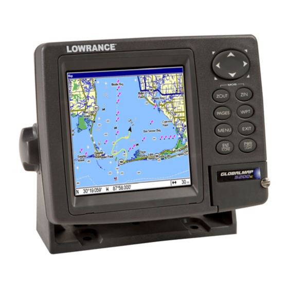
If you just can't wait to get outside, turn to the one-page Quick Reference on page 39. Keyboard The GlobalMap 5200c GPS unit Map Page, keyboard and access door 1. PWR/LIGHT (Power & Light) – The PWR key turns the unit on and off and activates the backlight. -
Page 32: Power/Lights On And Off
and Radar. Each page represents one of the unit's major operation modes. 3. MENU – Press this key to show the menus and submenus, which allow you to select a command or adjust a feature. This also accesses search functions for streets, intersections, addresses and highway exits. 4. - Page 33 Point of Interest or map cursor location; or after you reach the end of a route or trail. GPS Setup command: sets various GPS receiver options. System Setup command: sets general configuration options. NMEA 2000: provides access to all NMEA 2000 network setup options, including the configuration of devices on the network.
-
Page 34: (Satellite) Status Page
Browse Files command: this allows you to view the installed MMC card and the files it contains. Pages The unit has four Pages that represent the major operating modes. They are the Status, Navigation, Map and Radar Page. They are ac- cessed by pressing the Clear the Pages Menu by pressing (Satellite) Status Page... - Page 35 North is at the top of the screen. You can use this to see which satellites are obstructed by obstacles in your immediate area if the unit is facing north. The GPS receiver is tracking satellites that are in bold type.
- Page 36 Highlight P … and press ENT in the Overlay Data Shown RESS NT TO ADD menu (far left) to open the Data Viewer menu (center) with five ex- pandable data categories: GPS Data, Navigation, Trip Calculator, Time and Sensor Data. The right figure shows the subcategory list under the GPS Data category.
-
Page 37: Navigation Page
NOTE: One of the data display options for the Satellite Status page is "Po- sition Error" (horizontal position error), which can appear in one of the page's data boxes. When Position Error is on, it will show you the expected error from a benchmark location. In other words, if the Position Error box shows 50 feet, then the position shown by the unit is estimated to be within 50 feet of the actual location. - Page 38 When navigating to a waypoint your ground speed, track, distance and bearing to waypoint, and course are all shown digitally on this screen. NOTE: Remember, when the Speed, Track and Position information dis- plays are flashing, satellite lock has not been achieved and no posi- tion fix has been determined.
- Page 39 Left cross track error line Current track or heading, shown in degrees Compass bearing to destination Trail line Navigation information displays in data boxes Navigation Page, going to a waypoint while creating a new trail. The cross track error range is shown on the compass rose as a wide, white, corridor enclosing the course line.
-
Page 40: Map Page
The Navigation Page has its own menu, which is used for some ad- vanced functions and for setting various options. Options and setup are discussed in Sec. 5. To access the Navigation Page Menu, from the Navigation Page, press MENU Map Page The Map Page screens show your course and track from a "bird's-eye"... -
Page 41: Background Map Vs. Mapcreate Map Content
If you're using only the factory-loaded background map, the maximum zoom range for showing additional map detail is 20 miles. You can con- tinue to zoom in closer, but the map will be enlarged without revealing more map content (except for a few major city streets.) Load your own high-detail custom map made with MapCreate (or a pre-made Free- domMap from LEI), and you can zoom in to 0.02 miles with massive amounts of accurate map detail. - Page 42 What's more important is the large scale map detail that allows your GPS unit to show a higher level of position accuracy. For example, the background map would show you the general outline and approximate shape of a coastline or water body, but the higher de- tail in MapCreate shows the shoreline completely and accurately (finer detail).
-
Page 43: Resize Window Command
The Map Page has its own menu, which is used for several functions and for setting various options. To access the Map Page Menu, from the Map Page, press MENU The Pages Menu also offers several map display options under the Map Page category. - Page 44 Pages Menu with Two Maps option selected, at left. The Resize Win- dow feature was used to make the maps vertical. Map Page with two horizontal map windows, at right. The bottom map is the active map. Resize Window is a useful feature for pages that have two major win- dows.
-
Page 45: Basic Gps Quick Reference
You can only change size, not switch layout, on the Map With Custom Gauges - it's always two vertical windows. Press flashing arrows. 3. To change the window size again or revert back to the original dis- play, just follow the steps above. Most dual-window displays use half the screen for each window by default. -
Page 46: Find Your Current Position
Scroll map north, south, east or west using arrow keys ↑ ↓ → ← . To stop scrolling and return to current position on map, press 6. Set a waypoint (Wpt 001) at your current position so you can navi- gate back here: press 7. -
Page 47: Selecting Any Map Item With The Cursor
When you are traveling, the map will automatically move as you move. This keeps your current location roughly centered on-screen. You can manually pan or scroll the map north, south, east or west by using the arrow keys, which launch the cross-hair map cursor. This allows you to look at map places other than your current position. -
Page 48: Searching
Searching Now that you've seen how the unit can find where you are, let's search for something somewhere else. Searching is one of the most powerful features in the Lowrance GPS product line. In this example, we'll look for the nearest fast-food restaurant. For more information on different types of searches, refer to Sec. - Page 49 POI information screen on fast food restaurant nearest this position. Screen shows name, street address, phone number, latitude/longitude, distance to restaurant and its compass bearing. Figure at left shows Go To Waypoint command; right figure shows Find On Map command. 6.
-
Page 50: Set A Waypoint
Set a Waypoint A waypoint is an electronic "address," based on the latitude and longi- tude of a position on the earth. A waypoint represents a location, spot or destination that can be stored in memory, then recalled and used later for navigation purposes. - Page 51 Create Waypoint at Current Position While you are traveling, press automatically given a name with a sequential number, such as "way- point 003." The waypoint symbol and number appear on the map. Step 1. Step 3. Sequence for setting a waypoint. Step 1: while traveling, quickly press WPT twice to call up Find Waypoint screen (seen in Step 2) and set a point.
-
Page 52: Navigate To A Waypoint
Navigate to a Waypoint You can select any waypoint visible on the Map Page with the cursor, then use the Navigate to Cursor command (we'll describe how later in this section.) However, you can avoid scrolling the map to pick your waypoint if you use the Find Waypoint commands. -
Page 53: Navigate Back To Mob Waypoint
To activate it, press the tion at the time these keys are pressed is used as the man overboard position. Caution: Saving a new "Man Overboard" waypoint will overwrite and erase the previous "Man Overboard" waypoint. Navigate Back to MOB Waypoint Find your way back to the accident position with the Navigation Page or Map Page. - Page 54 2. Center the cursor over the location to select it. See the example in the following figure. Many map items such as waypoints, Points of In- terest, towns, etc. can be "selected," and appear "highlighted" with a pop-up box. Other features, such as a river or a street intersection will not appear "highlighted,"...
-
Page 55: Navigate To A Point Of Interest
To stop navigating to the cursor, use the Cancel Navigation command: press |↓ to MENU MENU stops showing navigation information. Navigate to a Point of Interest For POIs that are in view on the map, you can use the Navigate to Cur- sor command above;... - Page 56 To Save a Trail 1. Press MENU MENU Visible symbol Sequence for saving a trail and beginning a new one, after My Trails command is selected. The Trails Menu, at left. The arrow to the right of Trail 2 indicates the trail is "active" and the check to the left indicates the trail is visible on the map display.
-
Page 57: Displaying A Saved Trail
You can save and recall up to 10 different plot trails, which can also be copied to your MMC for archiving or for transfer to your MapCreate software. Tip: Another quick way to stop recording one trail and begin a new one is to use the New Trail command: Press RAILS Caution:... -
Page 58: Visual Trailing
The other two methods provide a full range of navigation data and work with both the Map Page and Navigation Page. The only difference between them is "navigating a trail" follows a trail forward (from start to end) while "backtracking" follows a trail in reverse (from end to start.) When hiking at walking speed with a hand-held GPS, we often just use visual back trailing because it is a bit better at following each little... - Page 59 Figure 1. Figure 2. Figure 3. Figure 4. Navigate a trail menu sequence: Fig. 1, My Trails command. Fig. 2, Trails Menu. Fig. 3, Edit Trail Menu. Fig. 4, Edit Route Menu for Trail 3. A trail is always converted to a "route" when you navigate the trail. On the Map Page, the trail you are navigating is represented by a dot- ted line that alternates with a flashing solid line.
- Page 60 Present position arrow Trail point Navigate trail, map views: at left driver is northbound heading straight toward trail point 6. At right, northbound driver has reached point 6 and has turned west to follow trail. Track or compass heading indicator Trail waypoint symbol...
-
Page 61: Transfer Custom Maps And Gps Data Files
5. Now, begin moving and follow the trail. 6. When you reach your destination, be sure to cancel your navigation: press |↓ to . The unit asks if you're MENU MENU ANCEL AVIGATION sure; press ←| Transfer Custom Maps and GPS Data Files Custom Maps: Custom maps work only from the MMC card or SD card. - Page 62 2. The Transfer My Data menu includes a message which tells you if an MMC is present or not. If no MMC is present, you must first insert a card into the unit in order to activate the Load or Save commands. To transfer data from the unit to the MMC: press To transfer data from the MMC to the unit: press →...
-
Page 63: Cancel Navigation
Figure 1. Figure 3. These figures show the menu sequence for loading a GPS Data File from an MMC into the unit's memory. Cancel Navigation You can turn off any of the navigation commands after you reach your destination or at any other time by using the Cancel Navigation com- mand. - Page 64 Notes...
-
Page 65: Section 4: Advanced Gps Operations
Advanced GPS Operations Find Distance From Current Position to Another Location 1. While on the Map Page press: 2. Center your cursor over the position you want to find the distance to. A rubber band line appears, connecting your current position to the cursor's location. -
Page 66: Icons
Icons Icons are graphic symbols used to mark a location, personal point of interest or event. They can be placed on the map screen, saved and re- called later for navigation purposes. These are sometimes referred to as event marker icons. This unit has 42 different symbols you can pick from when creating an icon. -
Page 67: Routes
1. Press |↓ to MENU 2. Press ↓ to ELETE press The Delete All Icons command will ask if you are sure. Press ← to . All icons will be deleted from the map. The Delete by Symbol command will launch the Select Symbol menu. Press ←... -
Page 68: Create And Save A Route
The course from one waypoint to the next is a leg; routes are composed of one or more legs. The legs of all GPS routes are based on straight lines between waypoints. A route provides the automatic capability to navigate through several waypoints without having to reprogram the unit after arriving at each waypoint. -
Page 69: Delete A Route
2. Press . Now ↓ to Map Page appears with the cursor showing. Edit Route menu, left. Edit Route Waypoints menu, right, with Add From Map command selected. 3. Use the Zoom keys and arrow keys to move the map and cursor until the cursor is centered on the spot where you want your route to begin. -
Page 70: Edit A Route Name
Tip: You can also delete all routes at once: 1. From the AVIGATION press MENU MENU 2. Press → to Edit a Route Name You can edit the route name if you wish. 1. From the AVIGATION |↓ to MENU MENU 2. -
Page 71: Navigate A Route
NOTE: When adding waypoints to a route, the inserted waypoints will ap- pear in the route in front of the waypoint you have selected. To in- sert waypoints at the end of the route, make sure to select "(End of route)"... -
Page 72: Trails
Figure 1. Figure 3. Navigating along a route: Fig. 1 shows the Navigation Page at the start of a route, heading straight for the first waypoint (Wpt 1). In Fig. 2, the traveler has arrived at Wpt 1; the arrival alarm has been triggered and the bearing arrow on the compass rose has turned to point toward Wpt 2, off to the east. -
Page 73: Edit A Trail Name
Edit a Trail Name To edit a trail name: press . Press ↑ or ↓ to change the first character, then press name| → to the next character and repeat until the name is correct. Press then EXIT EXIT EXIT Tip: You can quickly call up the Edit Trail menu by selecting a trail on the map with the cursor. -
Page 74: Utilities
At left, Edit Trail Menu with Pattern option selected. At right, edited trail with dotted line pattern. Utilities Utilities are useful tools for traveling or for outdoor activities. Alarm Clock To get to the alarm clock menu: press LARM LOCK Sun/Moon Rise &... -
Page 75: Edit A Waypoint
2. Press |→ to the previous page and clear the cursor, press To delete all waypoints at one time: press |↓ to ETUP ELETE to the previous page, press Edit a Waypoint Waypoint Name To edit waypoint name: 1. Press POINT 2. -
Page 76: Set A Waypoint By Projecting A Position
This boosts waypoint position accuracy by helping to eliminate errors caused by atmospheric conditions and other factors. 1. Press |→ to 2. Press ↓ or ↑ to VERAGE 3. Wait while the unit takes points to average for the position. The greater the number of points, the greater the accuracy. -
Page 77: Section 5: System & Gps Setup Options
Section 5: System & GPS Setup Options Alarms This unit has several GPS alarms. The factory default setting has all of these but the anchor alarm turned on. You can turn the alarms off and on and change their distance settings. You can set an arrival alarm to flash a warning message and sound a tone when you cross a preset distance from a waypoint. -
Page 78: Auto Satellite Search
It then searches for only those satellites. When your GPS receiver is turned on for the first time, it doesn't know what your position or elevation (altitude) is. It does know the current UTC time and date since these were programmed into it at the factory and an internal clock keeps the time while the unit is turned off. -
Page 79: Check Mmc Files And Storage Space
Check MMC Files and Storage Space To check MMC Files: Press |↓ to MENU MENU ENT. ROWSE ILES Main Menu, left, Browse Files, right. Communications Port Configuration The unit has one NMEA 0183 version 2.0 compatible communication port or com port for short. The Com Port Menu, which is accessed from the System Setup Menu, allows you to configure the communications port to send or receive data to another electronic device, such as an autopilot. -
Page 80: Configure Nmea
2. Press ↓ to OMMUNICATIONS Configure NMEA You can configure the unit to use specific NMEA sentences. 1. Press MENU MENU 2. Press ↓ to OMMUNICATIONS 3. A menu appears showing the prefixes of the available NMEA sen- tences. A check mark next to a prefix means the prefix is in use. Use ↑ ↓... -
Page 81: Map Fix
UTM's are marked on USGS topographic charts. This system divides the Earth into 60 zones, each 6 degrees wide in longitude. British, Irish, Finnish, German, New Zealand, Swedish, Swiss, Taiwan, and Greek grid systems are the national coordinate system used only in their respective countries. - Page 82 from that reference point. For example, if it shows a distance of UP 4.00" and LEFT 0.50", you then measure up four inches and to the left a half-inch from the reference point on the map to find your location. To configure a map fix: To use this format, you need to follow these steps in order.
-
Page 83: Customize Page Displays
Press → to ELECT Select the waypoint that you saved the reference point under and press . The unit displays a waypoint information screen with the com- mand RIGIN figure Map Fix menu. Finally, press EXIT , select information now shows as a distance from the reference point you chose. -
Page 84: (Gps) Simulator
Selecting the category name and pressing contents, so you can choose items within it. An expanded category (one with a "–" next to its name) can be collapsed to hide its contents. Just select the category name and press might contain data you want to display. Then press ↓ or ↑ to select a different data option. -
Page 85: Simulating Trail Or Route Navigation
A message and tone appear periodically, warning you that the simula- tor is on. To turn the simulator off, repeat the above steps or turn the unit off. While in simulator mode, you can press speed boxes from the screen while continuing the simulation. This will allow you to use the map cursor during a simulation. -
Page 86: Map Auto Zoom
2. A message appears, telling you to move the cursor near the desired location and press . When the message automatically clears, follow the message instructions. 3. In a moment, your present position marker arrow appears on the map in the location you selected with the cursor. The unit will consider that spot as its last known position until changed by either a live satel- lite lock-on or a new simulator location. -
Page 87: Map Boundaries
Show Map Data From the Map Page, press ARTH ETAIL want, from Off (so the unit operates like a GPS plotter) to High. After the option is set, press Pop-up Map Information From the Map Page, press . With the option highlighted, press NFORMATION on) and uncheck it (turn off.) After the option is set, press return to the page display. -
Page 88: Map Datum Selection
The large ring touching the left and right sides of the screen is 100 miles in diameter (same as the zoom range). The second smaller ring is 50 miles in diameter (always 1/2 the zoom range). The distance from your current position to the smaller ring (the ring's radius) is 25 miles (al- ways 1/4 the zoom range). -
Page 89: Map Detail Category Selection
Map Datum Menu. Map Detail Category Selection This menu determines which of the mapping features are shown on the screen. This includes, waypoints, trails, icons, cities, highways, etc. You can selectively turn on or off any of these items, customizing the map to your needs. -
Page 90: Map Orientation
Map Orientation By default, this receiver shows the map with north always at the top of the screen. This is the way most maps and charts are printed on paper. In Track Up mode, map shows "N" and arrow to indicate north. Map orientation at left is shown in north up and at right, track up. -
Page 91: Nauticpath™ Usa Marine Charts
Map Menu, left; Map Orientation menu with the North Up map orientation option selected, at right. NOTE: In North Up and Course Up, the present position arrow appears in the center of the map page. In Track Up, the position arrow ap- pears centered in the lower third of the page. -
Page 92: Port Information
To view Chart Note information: 1. Use the arrow keys to move the cursor over a Chart Note icon. When it's selected, a pop-up name box appears. 2. Press to display the Note Information screen. 3. To scroll through the Chart Note screen, use ↑ ↓ arrow keys to read the information. -
Page 93: Tidal Current Information
Port Services icon. NauticPath chart showing Port Services icon selected by cursor. When first highlighted, the Pop-Up name box appears. The Port Services information screen for a NauticPath chart contains all the service information in one window. 3. To scroll through the service information window, use ↑ ↓ to see the types of services available. -
Page 94: To View Tidal Current Information
present time. At larger zoom ranges, you can select the boxed "C" icon and it becomes an animated arrow with a pop-up name box. The name box disappears after a few seconds. Examples are displayed in the fol- lowing figures. To view Tidal Current information: 1. -
Page 95: Tide Information
The velocity scale at the top left side of the graph changes dynamically based upon the maximum velocity of the current for that day. Slack water, the period of little or no current, is represented by the Slack Wa- ter Line (SWL). The flood appears above the SWL and the ebb appears below the SWL. -
Page 96: Navionics ® Charts
To view tide information: 1. Use the arrow keys to move the cursor over a tide station icon. When it is selected, a pop-up name box appears. 2. Press to display the Tide Information screen. Current Time Line. MLLW Line Tide Table The Tide Information screen displays daily tidal data for this station on... -
Page 97: Overlay Data
play. NauticPath charts are ready for display as soon as they are inserted into the unit. Navionics charts must be inserted into the unit, then selected as a Map Choice option in the Map Data menu. To display a Navionics chart: 1. - Page 98 Overlay Data, with "Navigation," "Trip Calculator" and "Time" categories expanded to show their subcategories. To overlay information on your screen: 1. While on the Navigation Page or a Map Page, press |↓ to MENU OVERLAY DATA 2. You'll see a list of the overlay data currently shown, if any. Select and press .
-
Page 99: To Remove Overlaid Data
From Overlay Data Shown (left) press ENT to see Data Viewer (center). Select a category and press ENT ; then select information to float on To remove overlaid data: 1. While on the Page that shows the item or items you want to remove, press |↓... -
Page 100: Pop-Up Help
1. From one of the Map Pages, press 2. You'll see a list of the overlay data currently displayed. Select the item you want to move and press 3. The data begins to flash on your screen. Use any combination of →, ←, ↑... -
Page 101: Reset Options
System Setup menu, left, with Pop-up Help command highlighted. At right, this example shows the Pop-up Help message for the Go To Cursor command, located on the Map Menu. Reset Options To reset all features to their factory defaults: 1. Press MENU MENU NOTE:... -
Page 102: Set Language
slider bar is already selected. Press → or ← to move the ONTRAST bar. The left end of the scale is minimum contrast; the right end is maximum contrast. Screen Command, left, and Screen Menu with Contrast bar selected, right. To adjust the display's brightness: Press ↓... -
Page 103: Set Local Time
1. Press MENU MENU 2. Press ↓ to ANGUAGE 3. Use ↓ or ↑ to select a different language and press now appear in the language you selected. Set Local Time Using the correct local time setting is handy when estimating local ar- rival time while navigating. -
Page 104: Show Waas Alarm
The last field in this menu is to automatically adjust with the time change caused by Daylight Sav- ing Time. You should only have to set it once. You may select which set of rules matches DST in your region, or ac- cept the default. -
Page 105: Track Smoothing
Sounds command, left. At right, the Sounds menu. Once in the Sounds menu: To set Key Press Sounds: With the option highlighted, press check it (turn on) and uncheck it (turn off.) After the option is set, press to return to the page display. EXIT EXIT To set Alarm Sounds: Press ↓... -
Page 106: Delete All Trails
Main Menu, left, Trails Menu, center, Trail Options, right. Delete All Trails To remove all of the trails from memory: from the Trails Menu, press → |← to ELETE Update Trail Option This menu lets you change the way the trail updates occur. WARNING: If you uncheck the Update Trail option, automatic trail creation and recording will be turned off. -
Page 107: Delete Trail
Trail Options menu: Update Time Rate setting, left, and Update Distance setting, right. Specific Trail Options Delete Trail To delete a specific trail: From the Trails Menu, press ↓ to Trail Name| . The Edit Trail menu appears as seen in the following fig- ure. -
Page 108: Transparency
New Trail To manually start a new trail, in the Trails Menu, make sure is highlighted and press New Trail command highlighted. Transparency Use the transparency menu to adjust the transparency of menu win- dows. A high transparency allows you to continue monitoring the screen's display while adjusting feature settings, though the text of the menus may fade until it is unreadable. -
Page 109: Units Of Measure
To adjust Menu Transparency level: Press MENU MENU appears. Press ↑ or ↓ to move the bar. The lower end of the scale makes the menus opaque; the upper end is maximum transparency. Units of Measure This menu sets the speed and distance (statute or nautical miles, me- ters), depth (feet, fathoms, or meters), temperature (degrees Fahren- heit or Celsius) and heading (true or magnetic) units. - Page 110 Notes...
-
Page 111: Section 6: Searching
Section 6: Searching NOTE: The Search function depends on the type of map data loaded in your unit. GlobalMap HD models are fully "searchable" out of the box because they contain a hard drive loaded with complete map- ping information. These maps include all the data contained in our MapCreate custom maps, Fishing Hot Spots lake maps and Nau- ticPath coastal charts. -
Page 112: Find Addresses
mined). You can look up items by name, or search for the item nearest to you. Find Addresses 1. From the Map Page, press |↓ to MENU DDRESS 2. Press to search in the Address field. 3. To enter an address number, press ↑ or ↓ to change the first number, then press →... - Page 113 5. To enter a city name, press ↓ to want to find addresses only within a particular city. This option is de- signed so you can limit an address search to a single city if necessary (see note below.) If you select yes, there are two options: A. You can spell out the city name in the top selection box.
- Page 114 Address search result list, left. At center, Map Page showing location of the address on the map, highlighted by cursor. At right, after the address is located, you can navigate to it ("D" symbol for destination). 8. To navigate to the address, press begin showing navigation information to the address pointed out by the cursor.
-
Page 115: Find Any Item Selected By Map Cursor
Find Any Item Selected by Map Cursor On the Map Page: with a POI or map feature selected by the cursor press To return to the previous page, press WPT. A POI selected by the cursor, left, POI information screen, right. NOTE: Since the Go To Waypoint command is highlighted, you can navi- gate to the selected POI by pressing... - Page 116 Press ↑ or ↓ to change the first letter, then press → to move the cursor to the next letter and repeat until the name is correct, then press . B. Jump down to the lower selection list by pressing then press ↓...
-
Page 117: Find Map Places Or Points Of Interest (Poi)
"Go To Exit" option, left, "Find On Map" option, right. Tip: You can also look up some additional information on the Exit Ser- vices located near this exit. Press ↓ to lect Service Name| Exit Information screen, left; general location and amenities information, at right. - Page 118 Find Waypoint menu with Lodging POI category selected, left, and with the RV Parks subcategory selected, right. 2. Search by nearest POI. Press ↓| will show a "calculating" screen, then a list of the nearest POI's will appear. Press ↓ or ↑ to the selected POI and press POI's Waypoint Information screen.
-
Page 119: Find Streets Or Intersections
Find by Name option, left, Find by Name menu, right. 4. When the POI's Waypoint Information screen is displayed, you can choose to "Go To" the POI waypoint by pressing or find it on the map by pressing ↓| "Go To" POI option, left, "Find on Map" POI option, right. Find Streets or Intersections Find a Street 1. - Page 120 Find Streets command, left, Find Streets menu, right. 2. You must first fill in a street name in the First Street dialog box. Press to display the Find By Name menu. There are two options: A. You can spell out the street in the top selection box. Press ↑ or ↓ to change the first letter, then press →...
-
Page 121: Find An Intersection
At left, the Find Streets menu with the Find First Street command highlighted. At right, Streets Found list. 4. The Map Page appears, with the cursor pointing to the found street. If you want to navigate to the found street at the cursor location, press MENU EXIT Map Page showing results of a street search. - Page 122 repeat until the name is correct, then press jump down to the lower box and pick a street from the selection list. Press , then press ↓ or ↑ to select a street from the list and press 3. The Find Streets menu reappears with the street you're searching for in the First Street box.
-
Page 123: Find Waypoints
7. The Map Page appears, with the cursor pointing to the found inter- section. The intersection in our example is shown in the following fig- ure. If you want to navigate to the found intersection, just press MENU EXIT Find Waypoints 1. - Page 124 Waypoint Information screens with the Go To Waypoint command se- lected, left, and the Find on Map command selected, right. To clear these menus and return to the previous page, press EXIT peatedly. 5. If you're looking by name, there are two options: A. You can spell out the name in the top selection box.
-
Page 125: Section 7: Nmea 2000 Device Configuration
Section 7: NMEA 2000 Device Configuration NMEA 2000 Menu The NMEA 2000 menu on your display unit's main menu allows you to configure, calibrate and monitor devices on a NMEA 2000 network. The NMEA 2000 menu provides access to the Bus Setup, Fuel Management and NMEA 2000 Alarms. -
Page 126: Engine & Tank Configuration
The NMEA Diagnostics page displays information about the perform- ance of the network bus, keeping you updated on bus status, mode, er- rors and bus traffic. The Ethernet Diagnostics page keeps you updated on the performance of an Ethernet connection (if applicable) supplying information ranging from IP Address to upload and download rates (bytes per second). - Page 127 When choosing an engine-tank configuration you will use the Tank Se- lect menu, Tank Size dialog box and Set configuration button, all de- tailed below. Tank Select The Tank Select menu allows you to choose from up to three tanks (Port, Center and Starboard), depending on the Engine-tank configura- tion that has been selected.
-
Page 128: Device Configuration Menu
. Press → to high- 6. Select the tank you want to set up and press light the Tank Size dialog box and press 7. Use ↓ ↑, ← → to input the capacity (gallons) of the tank you chose from the Tank Select menu and press 8. -
Page 129: Fuel Management Menu
If, for example, you are viewing the device configuration menu for an EP-15 Fluid Level, the device data window will include tank size and the amount of fuel left in the tank. The Device Data for an EP-10 Fuel Flow includes Fuel Rate (amount of fuel burned per hour), Fuel Used, Trip Fuel Used and Seasonal Fuel Used. -
Page 130: Adding Fuel To Tank
Fuel Added Used in tandem with the Add Fuel command, the Fuel Added dialog box allows you to input the amount of fuel added to the tank, when an amount of fuel is added that does not fill up the tank. Add Fuel After entering the amount of fuel added to a tank in the Fuel Added dialog, the Add Fuel command finalizes the entry of the data. -
Page 131: Engine Operations
Engine Operations The lower half of the Fuel Management menu contains the following Engine Operation functions: Engine Select, Reset Calibration, Reset Trip and Reset Seasonal. Engine Select Engine Select allows you to choose the desired engine when resetting calibration, resetting trip fuel and resetting seasonal fuel. To Reset Calibration: Choosing the Reset Calibration command will switch fuel flow calibra- tion settings back to factory defaults. -
Page 132: Nmea 2000 Alarms
NMEA 2000 Alarms The NMEA 2000 Alarms menu allows you to set Full and Empty fuel alarms for the EP-10 Fuel Flow, EP-15 Fluid Level, EP-50 Storage De- vice and the Suzuki Engine Interface. The alarms may be set to a per- centage (0-100%) of tank capacity. -
Page 133: Configuring Ep Sensors
set the backlight level to 75 percent on one display unit, all other units on the network will automatically switch to the same setting. To turn on/off Backlight Synchronization: 1. Press MENU MENU 2. Highlight ACKLIGHT on/off Backlight Synchronization. 3. Press repeatedly to get back to the main display. -
Page 134: Advanced Options Menu
5. Highlight the desired Temp Type and press firmation message will appear: Are you sure you wish to change this device's configuration? 6. Highlight and press main display. Advanced Options menu The Temp sensor Advanced Options menu contains two categories: In- stance and Restore Defaults. - Page 135 EP-10 Fuel Flow Configuration To input Device Name: 1. Press MENU| MENU NMEA 2000 menu will appear with five options: Bus Setup, Fuel Man- agement, NMEA 2000 Alarms, Waypoint Sharing and Backlight Syn- chronization. 2. Highlight ETUP ration menu. A list of network devices will be at the top of the page. 3.
- Page 136 You shouldn't need this command if you are connecting your unit to a network with similar display units and/or a series of electronic probes. Restore Defaults The Restore Defaults command allows you to reset an individual EP-10 Fuel Flow Sensor's settings to factory defaults. If, for example, you exe- cute the Restore Defaults command from your Port Fuel Flow Ad- vanced Options menu, only the settings for the Port Fuel Flow will be reset to factory defaults.
- Page 137 To select Tank Instance (Location): 1. Press MENU| MENU NMEA 2000 menu will appear with five options: Bus Setup, Fuel Man- agement, NMEA 2000 Alarms, Waypoint Sharing and Backlight Syn- chronization. 2. Highlight ETUP ration menu. A list of network devices will be at the top of the page. 3.
- Page 138 2. Highlight ETUP ration menu. A list of network devices will be at the top of the page. 3. Select the desired fluid level and press Configuration menu will appear. 4. Highlight the tank and press Enter. The following message will appear: Are you sure you wish to change this device's configuration? 5.
-
Page 139: Suzuki Engine Interface Configuration
5. Select ESTORE appear: Are you sure you wish to change this device's configuration? 6. Highlight and press main display. NOTE: The Fluid Level Device Configuration menu also contains the Cali- brate button, but we will address that later in the segment covering Calibration. - Page 140 agement, NMEA 2000 Alarms, Waypoint Sharing and Backlight Syn- chronization. 2. Highlight ETUP ration menu. A list of network devices will be at the top of the page. 3. Use ↑ ↓ to select the desired engine interface and press vice Configuration menu will appear.
-
Page 141: Calibrating Ep Sensors
3. Use ↑ ↓ to select the desired fluid level and press Configuration menu will appear. 4. Highlight DVANCED 5. Select ESTORE appear: Are you sure you wish to change this device's configuration? 6. Highlight and press main display. NOTE: The Suzuki Engine Interface Device Configuration menu contains two Engine Trim calibration commands, which will be addressed in the next segment of this section, Calibrating EP Sensors. - Page 142 8. Take your vessel out on the water and burn at least five gallons of fuel. Be sure you run only ONE engine — the engine connected to your fuel flow. 9. Fill up your tank again, noting how much fuel you added to the tank. Compare that number to the Fuel Used figure displayed on the page you customized.
-
Page 143: Ep-15 Fluid Level Calibration
EP-15 Fluid Level Calibration The default calibration for the EP-15 Fluid Level is just as accurate as standard fluid level gauges. If, however, the tank has an irregular shape or greater accuracy is needed, calibration is recommended. There are three calibration options: 2-Point, 3-Point and 5-Point. 2-Point Calibration A 2-point calibration is best suited for rectangular or square-shaped tanks, where the capacity of the top half of the tank matches the capac-... - Page 144 Calibrate is highlighted on the device configuration menu (left). Cali- bration menu (right) with calibration instructions listed at the top. 3-Point Calibration 3-point calibration is designed for tanks that vary in shape from the top to the bottom. You can begin calibration at any point in the 3-point process, but we recommend starting calibration with an empty tank.
- Page 145 Highlight ALIBRATE pear: Full Level Calibration Completed. Press peatedly to get back to the main display. Num Pts menu with 5-point calibration selected (left). Half level se- lected on Fluid Level menu (center). Calibration Done window (right). 5-Point Calibration 5-point calibration is best suited tanks that vary greatly in shape from top to bottom.
-
Page 146: Fuel Flow Calibration In A Suzuki Engine Interface
Select and press ALIBRATE Qtr Level Calibration Completed. Press 10. Add another quarter tank of fuel, which should raise the fuel level to half a tank. Highlight press ENT . Highlight ALIBRATE pear: Half Level Calibration Completed. Press 12. Add another quarter tank of fuel, which should raise the fuel level to 3 quarters of a tank. -
Page 147: Engine Trim Calibration
9. Fill up your tank again, noting how much fuel you added to the tank. Compare that number to the Fuel Used figure displayed on the page you customized. If the amount of fuel you added to the tank and the fuel used figure are off by more than 3 percent, we recommend the en- gine interface be calibrated. -
Page 148: Reset Trim Calibration
Reset Trim Calibration If you are not satisfied with your engine trim calibration, you can reset engine trim calibration from the Suzuki Engine Interface Advanced Options menu. 1. Press MENU MENU 2. Choose ETUP connected to the desired engine and press 3. - Page 149 5. Highlight and press . The following message ESET ALIBRATION will appear: Are you sure you wish to Reset Calibration? 6. Highlight and press . Press repeatedly to get back to the EXIT main display.
- Page 150 Notes...
-
Page 151: Sec. 8: Supplemental Material
Sec. 8: Supplemental Material Datums Used by This Unit WGS 1984 Default Adindan Mean for Ethiopia, Sudan Adindan Burkina Faso Adindan Cameroon Adindan Ethiopia Adindan Mali Adindan Senegal Adindan Sudan Afgooye Somalia Ain el Abd 1970 Bahrain Ain el Abd 1970 Saudi Arabia Anna 1 Astro 1965 Cocos Islands... - Page 152 Chatham Island Astro 1971; New Zealand (Chatham Island) Chua Astro Paraguay Corrego Alegre Brazil Dabola Guinea Djakarta (Batavia) Indonesia (Sumatra) DOS 1968 New Georgia Islands (Gizo Island) Easter Island 1967 Easter Island European 1950 Mean for Austria, Belgium, Denmark, Finland, France, West Germany, Gi- braltar, Greece, Italy, Luxembourg, Nether-...
- Page 153 Nahrwan United Arab Emirates Naparima BWI Trinidad & Tobago North American 1927 Mean for Antigua, Barbados, Barbuda, Caicos Islands, Cuba, Dominican Republic, Grand Cayman, Jamaica, Turks Islands North American 1927 Mean for Belize, Cos- ta Rica, El Salvador, Guatemala, Hondu- ras, Nicaragua North American 1927 Mean for Canada...
- Page 154 Point 58 Sweden Santo (DOS) 1965 Espirito Santo Island Sao Braz Azores (Sao Miguel, Santa Maria Islands) Sapper Hill 1943 East Falkland Island Schwarzeck Nambia Selvagem Grande Salvage Islands SGS 85 Soviet Geodetic Sys- tem 1985 South American 1969 Mean for Argentina, Bolivia, Brazil, Chile, Colombia, Ecuador, Guyana, Paraguay,...
- Page 155 Notes...
- Page 156 Notes...
- Page 157 Notes...
-
Page 158: Fcc Compliance
FCC Compliance This device complies with Part 15 of the U.S. Federal Communi- cations Commission (FCC) Rules. Operation is subject to the fol- lowing two conditions: (1) this device may not cause harmful inter- ference, and (2) this device must accept any interference received, including interference that may cause undesired operation. - Page 159 LOWRANCE DATABASES LICENSE AGREEMENT THIS IS A LEGAL AGREEMENT BETWEEN THE END-USER WHO FIRST PURCHASES THIS PRODUCT AS A CONSUMER ITEM FOR PERSONAL, FAMILY, OR HOUSEHOLD USE ("YOU") AND LOWRANCE ELECTRONICS, INC., THE MANUFACTURER OF THIS PRODUCT ("WE", "OUR", OR "US"). USING THE PRODUCT ACCOMPANIED BY THIS LICENSE AGREEMENT CONSTITUTES ACCEPTANCE OF THESE TERMS AND CONDITIONS.
-
Page 160: Databases Limited Warranty
DATABASES LIMITED WARRANTY "We", "our", or "us" refers to Lowrance Electronics, Inc., the manufacturer of this product. "You" or "your" refers to the first person who purchases the prod- uct as a consumer item for personal, family, or household use. The Databases Limited Warranty applies to the one or more databases that your product may contain. - Page 161 LOWRANCE ELECTRONICS FULL ONE-YEAR WARRANTY "We," "our," or "us" refers to LOWRANCE ELECTRONICS, INC., the manufacturer of this product. "You" or "your" refers to the first person who purchases this product as a consumer item for personal, family or household use. We warrant this product against defects or malfunctions in materials and workmanship, and against failure to conform to this product's written specifications, all for one (1) year from the date of original purchase by you.
-
Page 162: How To Obtain Service
How to Obtain Service… …in the USA: We back your investment in quality products with quick, expert service and genuine Lowrance parts. If you're in the United States and you have technical, return or repair questions, please contact the Factory Customer Service Department. -
Page 163: Accessory Ordering Information
Accessory Ordering Information for all countries To order Lowrance GPS accessories such as power cables or MMC cards, please contact: 1) Your local marine dealer, sporting goods or consumer electronics store. Most quality dealers that handle marine electronic equipment or other consumer electronics should be able to assist you with these items. -
Page 164: Visit Our Web Site
Visit our web site: Lowrance Pub. 988-0151-471 © Copyright 2006 All Rights Reserved Printed in USA 120706 Lowrance Electronics, Inc.