Table of Contents
Advertisement
Quick Links
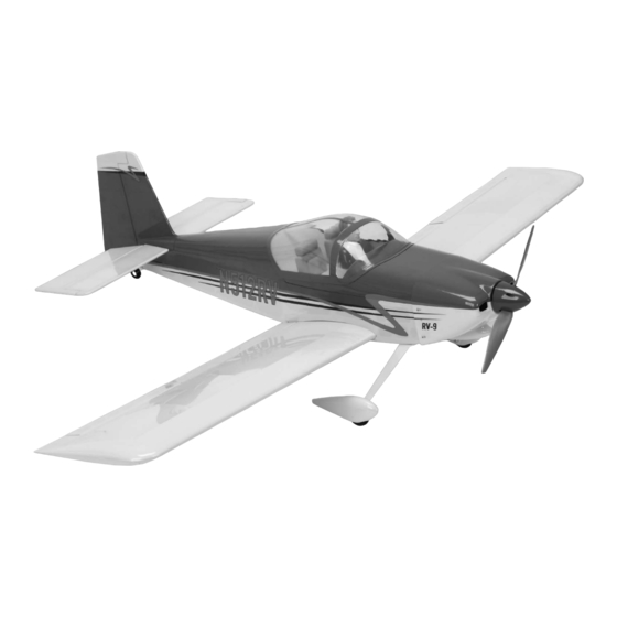
RV-9 450
Assembly Manual
Specifications
Wingspan:
Length:
Wing Area:
Weight w/o Battery:
Weight w/Battery:
50 in (1270mm)
38 in (920mm)
385 sq in (24.8 sq dm)
31–34 oz (875–965 g)
36–40 oz (1020–1135 g)
Pilot figure sold separately (EFLA156)
RV-9 is a trademark of Van's Aircraft and is used with permission.
Advertisement
Table of Contents

Related Manuals for E-FLITE RV-9 450


Summary of Contents for E-FLITE RV-9 450
- Page 1 RV-9 450 Assembly Manual Specifications Wingspan: 50 in (1270mm) Length: 38 in (920mm) Wing Area: 385 sq in (24.8 sq dm) Weight w/o Battery: 31–34 oz (875–965 g) Pilot figure sold separately (EFLA156) Weight w/Battery: 36–40 oz (1020–1135 g) RV-9 is a trademark of Van’s Aircraft and is used with permission.
-
Page 2: Table Of Contents
Tail Installation ............4 Register your product online at: Main Radio Installation ........... 7 In the air, the RV-9 450 offers a nice balance between www.e-fliterc.com/register/ Rudder and Elevator Linkage Installation ....9 maneuverability and stability that will please both Aileron Servo and Linkage Installation .... -
Page 3: Recommended Radio Equipment
Propeller Electric Propeller, 10 x 7E 6-channel system. If using your own transmitter, we Rubbing alcohol Ruler (APC10070E) recommend the S75 Sub-Micro Servos from E-flite. Scissors Side cutters Threadlock Waxed paper Recommended High Power Setup If you own the Spektrum DX6i radio, just add the... -
Page 4: Landing Gear Installation
1. Locate the horizontal stabilizer. The top of the stabilizer has the blind nut for attaching it to the fuselage on the top side of the stabilizer. The main gear will angle back when installed as shown in the photo. E-flite RV-9 450 Assembly Manual... - Page 5 4. Fit the tail assembly to the fuselage. Make sure to slide the tail post of the vertical fin into the slot at the aft end of the fuselage. The assembly should fit tightly in against the fuselage as shown. E-flite RV-9 450 Assembly Manual...
- Page 6 The control horn and backplate must be tight against the control surface or there will be play between the servo and surface. Use care when installing the control horn to make sure it is done correctly. E-flite RV-9 450 Assembly Manual...
-
Page 7: Main Radio Installation
Set the canopy hatch aside. 3. Remove the servo from the servo tray. Use a pin drill and 1/16-inch (1.5mm) drill bit to drill two holes in the servo tray as marked in the previous step. E-flite RV-9 450 Assembly Manual... - Page 8 If you are installing the operational flaps, it in the servo tray. Tighten the screws using a #1 you will also want to plug a 3-inch (76mm) servo Phillips screwdriver. extension in the flap (or AUX) port of the receiver. E-flite RV-9 450 Assembly Manual...
-
Page 9: Rudder And Elevator Linkage Installation
3. Insert the nylon pushrod connector in the hole enlarged in the last step. Use pliers to press the backplate onto the connector. 4. Repeat Steps 2 and 3 to prepare a second servo horn. E-flite RV-9 450 Assembly Manual... - Page 10 5mm machine screw to secure the pushrod to the pushrod connector. Use caution not to over-tighten the screw and damage the pushrod connector. 7. Slide a clevis retainer onto a clevis. Thread the clevis 16-turns onto the 17 -inch (450mm) rudder pushrod. E-flite RV-9 450 Assembly Manual...
-
Page 11: Aileron Servo And Linkage Installation
(both operational and fixed) as shown in the photo below. It is possible that you could accidentally prepare two identical aileron servos using the flap servo cover. E-flite RV-9 450 Assembly Manual... - Page 12 the radio system to center the servos. Use a #00 Phillips servo to install the servo horns back on the aileron servos. Prepare a right and left aileron servo at this time as shown. E-flite RV-9 450 Assembly Manual...
- Page 13 (1.5mm) drill bit to drill the holes for the servo provided with the servo to secure it to the servo 11. Repeat Steps 3 through 10 to prepare the mounting screws. mounting blocks. second aileron servo. E-flite RV-9 450 Assembly Manual...
- Page 14 15. Secure the servo cover to the wing using four 2mm x 6mm sheet metal screws. Use a #1 Phillips screwdriver to tighten the screws. E-flite RV-9 450 Assembly Manual...
- Page 15 16-turns onto a 2 -inch (60mm) aileron pushrod wire. Use rubbing alcohol and a paper towel to remove the line drawn on the bottom of the aileron before installing the control horn permanently. E-flite RV-9 450 Assembly Manual...
-
Page 16: Joining The Wing Panels
Slide the joiner into the tube. 1. Locate the aluminum wing joiner. Slide the joiner into one of the wing panels. E-flite RV-9 450 Assembly Manual... - Page 17 Use a felt-tipped pen to alignment with each other while the epoxy cures. transfer the outline of the plate onto the bottom of the wing. E-flite RV-9 450 Assembly Manual...
-
Page 18: Fixed Flap Linkage Installation
2. Thread the flap control horns on the flap control rods until the top of the horn is aligned with the top of the threaded rod. E-flite RV-9 450 Assembly Manual... - Page 19 Position the servo cover and use d #1 Phillips harder surface, making the screws more secure screwdriver to install the four 2mm x 8mm sheet when installed. metal screws that secure the cover to the wing. E-flite RV-9 450 Assembly Manual...
-
Page 20: Operational Flap Linkage Installation
16 turns. when installed. 2. Thread the flap control horns on the flap control rods until the top of the horn is aligned with the top of the threaded rod. E-flite RV-9 450 Assembly Manual... - Page 21 Use a pencil to mark the location of the two servo mounting tabs on the servo cover. E-flite RV-9 450 Assembly Manual...
- Page 22 17. Check the operation of the flaps at up, half and down flap. You may need to use a computer radio to set the positions according to the throws listed in this manual. FULL FLAP E-flite RV-9 450 Assembly Manual...
-
Page 23: Motor Installation
We have shown three positions for the flaps. If you are using a transmitter with only a 2-position switch, then the half flap position would not be used. Flap throws are covered at the end of the manual. E-flite RV-9 450 Assembly Manual... - Page 24 6. Check the operation of your motor at this time using the radio system. The motor should spin counterclockwise when viewed from the front of the fuselage. If not, follow the speed control manufacturer’s recommendations to reverse the direction if necessary. E-flite RV-9 450 Assembly Manual...
-
Page 25: Cowling Installation
Use a 2mm x 8mm machine screw to help in aligning the hole in the cardstock with the insert in the fuselage. E-flite RV-9 450 Assembly Manual... -
Page 26: Wheel And Wheel Pant Installation
If not it may be necessary to reposition the propeller by loosening the nut and moving the propeller. Use a #0 Phillips screwdriver to tighten the spinner mounting screws. E-flite RV-9 450 Assembly Manual... - Page 27 (1.5mm) away from the edge of the outer axle nut as shown. 6. Use your 1.5mm hex wrench or ball driver to tighten the setscrew to secure the outer wheel collar. Make sure the wheel can rotate freely on the axle. E-flite RV-9 450 Assembly Manual...
-
Page 28: Canopy Detail Installation
Make sure that the hatch is fully seated on the fuselage and the magnet in engaged during this step. If it is not seated and engaged it could cause your hatch to fit improperly or not engage once the canopy is glued on. E-flite RV-9 450 Assembly Manual... -
Page 29: Wing Installation
(and flap servo) are inside the fuselage. The wing is held in position using two 4-40 x 1-inch socket head screws and two #4 washers. Use a 3/32-inch ball driver or hex wrench to tighten the screws. E-flite RV-9 450 Assembly Manual... -
Page 30: Control Throws
You can experiment with higher rates to match your preferred style of flying. Travel Adjust, Sub Trim and Dual Rates are not listed and should be adjusted according to each individual model and preference. E-flite RV-9 450 Assembly Manual... -
Page 31: Preflight
Repair or replace any items that would be considered questionable. Failure of any of these components in flight would mean the loss of your aircraft. E-flite RV-9 450 Assembly Manual... -
Page 32: Safety Do's And Don'ts For Pilots
Horizon. Return of any goods by Purchaser must be approved in writing by Horizon before shipment. E-flite RV-9 450 Assembly Manual... - Page 33 Provided warranty conditions have been met, or concerns regarding this product or warranty. your Product will be repaired or replaced free of charge. Repair or replacement decisions are at the sole discretion of Horizon Hobby. E-flite RV-9 450 Assembly Manual...
-
Page 34: Instructions For Disposal Of Weee By Users In The European Union
This does not apply to model aircraft flown indoors. I will not operate model aircraft with metal-blade propellers or with gaseous boosts (other than air), nor will I operate model aircraft with fuels containing tetranitromethane or hydrazine. E-flite RV-9 450 Assembly Manual... - Page 35 Radio-controlled night flying is limited to low- am assisted by an experienced pilot. performance model aircraft (less than 100 mph). The model aircraft must be equipped with a lighting system which clearly defines the aircraft’s attitude and direction at all times. E-flite RV-9 450 Assembly Manual...
- Page 36 © 2009 Horizon Hobby, Inc. 4105 Fieldstone Road Champaign, Illinois 61822 (877) 504-0233 horizonhobby.com E-fliteRC.com Printed 04/09 15391.1...