Table of Contents
Advertisement
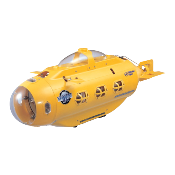
Neptune Submarine KIT & SC
Please read all instructions thoroughly before assembling the kit.
The contents are subject to change without prior notice due to product improvements and specification changes.
Thunder Tiger Corporation guarantees this model kit to be free from defects in both material and workmanship. The
total monetary value under warranty will in no case exceed the cost of the original kit purchased. This warranty does
not cover any components damaged by use or modification. Part or parts missing from this kit must be reported
within 60 days of purchase. No part or parts will be sent under warranty without proof of purchase. To receive part
or parts under warranty, the service center must receive a proof of purchase and/or the defective part or parts. Should
you find a defective or missing part, contact the authorized Thunder Tiger Service/Distributor nearest you. Under no
circumstances can a dealer or distributor accept return of a kit if assembly has started.
No.5220-K
No.5220-F
Advertisement
Table of Contents

Related Manuals for THUNDER TIGER Neptune SB-1


Summary of Contents for THUNDER TIGER Neptune SB-1
- Page 1 The contents are subject to change without prior notice due to product improvements and specification changes. Thunder Tiger Corporation guarantees this model kit to be free from defects in both material and workmanship. The total monetary value under warranty will in no case exceed the cost of the original kit purchased. This warranty does not cover any components damaged by use or modification.
-
Page 2: Table Of Contents
1 underwater R/C model by Thunder Tiger. Equipped with high technology operating equipment in the inner hull tube, covered by the brilliantly yellow color outer hull, the NEPTUNE SB-1 will let you enjoy the otherwise hidden, underwater world. -
Page 3: Battery Charging
1. This radio control submarine is not a toy. If not properly assembled and operated, it is capable of causing property damage. Thunder Tiger and it’s distributor have no control over damage resulting from shipping, improper construction, or improper usage. - Page 4 ASSEMBLY SECTION Most parts in the kit version are organized and packed in difference bags & Box. The packages are according to the assembly step and all the bag/box No are shown on the outside of the package. Basically, the electronic are package in Box1~Box4 and other parts are packaged in the Bag-A~ Bag-I.
- Page 5 FRONT FLANGE UNIT ASSEMBLY Bind Post(Red), BAG A BAG B qty 1 Switch Mount, qty 2 Bind Post(Black), Rod Mount, qty 1 qty 2 Fuse Holder, Control Arm, qty 1 Mounting Frame-B, qty 2 W.P. Bolt, qty 1 Fuse, qty 2 Bolt, M16, qty 1 qty 1...
- Page 6 1.1.3 SWITCH LINKAGE ARM 1.1.4 MOUNTING BOLT & CONE RUBBER M3x6mm M3x8mm M3x6mm M3x8mm M6x38mm Socket Head Machine Screw Lock Nut Hex Head Sscrew POWER DISTRIBUTION UNIT 1.2.1 FUSE 1.2.2 CHARGING BINDING POST Note: The spring washer & nuts already installed on the Binding Post. Remove that before assembly.
- Page 7 1.2.3 POWER 1.2.4 MOUNTING FRAME 1.2.5 UNIT DISTRIBUTION ASSEMBLY BOARD M4x60mm Ø4mm M3x10mm Hex Head Sscrew Spring Washer BT Phillip Tap Screw COMPLETE FRONT FLANGE UNIT ASSEMBLY 1.3.1 INSTALLATION OF SWITCH 1.3.2 INSTALLATION OF POWER LINKAG DISTRIBUTION UNIT M3x4mm M3x16mm M3x3mm Ø3mm Socket Head Machine Screw...
- Page 8 REAR FLANGE UNIT ASSEMBLY BAG C BAG D Mounting Rod Mount, Rod Mount, Frame-B, qty 5 qty 2 qty 1 RR Flange, Nut,M16, Mounting Servo Arm, qty 1 qty 1 Frame-A, qty 2 qty 1 Cone Rubber, Water Inlet, qty 6 qty 1 Spacer Tube, Linkage Rod,...
- Page 9 2.1.4 CONTROL ARM 2.1.5 MOUNTING BOLT & CONE RUBBER M3x6mm M6x38mm Socket Head Machine Screw Lock Nut Hex Head Sscrew SERVO UNIT 2.2.1 MOUNTING FRAME 2.2.2 SERVOS 2.2.3 SERVO ARM M4x60mm Ø4mm M3x10mm M2.6x8mm Hex Head Sscrew Spring Washer BT Phillip Tap Screw w/washer BT Phillip Tap Screw Lock Nut...
-
Page 10: Front Elevator Bracket
COMPLETE REAR FLANGE UNIT ASSEMBLY M3x16mm M3x4mm BT Phillip Tap Screw Socket Head Machine Screw OUTER FRAME ASSEMBLY BAG E Rod Mount, qty 1 AL Tube,L43.5mm, Outer Ring Frame, qty 2 qty 2 AL Tube, L150mm, FR Elevator Bracket, qty 4 qty 1 FR Elevator Linkage, Arm,... -
Page 11: Bottom Plate
BOTTOM PLATE BRACKET INSTALLATION LINKAGE ROD AL Tube, L43.5mm(2) M3x12mm Ø6mm Ø6mm M3x4mm BT Phillip Tap Screw w/washer Spring Washer Washer Socket Head Machine Screw INNER STRUCTURE ASSEMBLY BAG F 1st Inner 5th Inner Spacer Collar, Frame, qty 1 Frame, qty 1 qty 4 6th Inner 2nd Inner... -
Page 12: Frame W/Pump Unit
INNER FRAME W/RECEIVER M3x8mm BT Phillip Machine Screw FRAME W/PUMP UNIT 4.3.1 MOTOR MOUNTING 4.3.2 ROLLER PUMP 4.3.3 FRAME W/PUMP UNIT M3x8 M3x10 M3x10 CT Phillip Machine Screw BT Phillip Machine Screw BT Phillip Machine Screw Lock Nut... - Page 13 FRAME W/SPEED CONTROLLER M3x8 BT Phillip Machine Screw COMPLETE INNER FRAMES ASSEMBLY 4.5.1 & 2 INNER FRAMES 4.5.2 & 4 INNER FRAMES ASSEMBLY ASSEMBLY L30mm(6) L30mm(4) L210mm Spacer L60mm(3) Collar(4) L335mm(2) L240mm L60mm(2) Ø4mm Washer...
- Page 14 4.5.3 INNER FRAME ASSEMBLY 4.5.4 INNER FRAME ASSEMBLY Ø4 Washer L30mm(3) M4 Nut(4) M4 Nut Spacer Washer Spacer Ø4mm Washer Washer L60mm L60mm(2) L30mm(4) Ø4mm Ø4mm Washer Washer 4.5.5 BALLAST TANK & PRESSURE SENSOR Pressure Sensor Pump Ballast Water inlet/outlet tube (RR Flange) 3-Way One-Way...
- Page 15 4.5.6 SERVO/WIRE & BATTERY INSTALLATION Power PCB) Power Distribution PCB) CONNECTING OF THE WIRES ON THE RECEIVER Due to the difference radio system(Futaba, JR..) the wires have to be installed into the correct channel ports on the receiver. All the wires have the difference colors, please refer the following wire function table to do the installation.
-
Page 16: Motor W/Drive Cup
PROPULSION SYSTEM W/REAR COVER ASSEMBLY BAG G Drive Shaft, qty 1 Motor Mount, RR Cover Plate, BOX 4 qty 1 qty 1 Drive Cup, Drive Cup(motor), (IDØ4mm) (IDØ3.17mm) qty 1 qty 1 Propulsion Motor, Dogbone, Sealed Rubber, qty 1 qty 1 qty 1 MOTOR W/DRIVE CUP MOTOR MOUNTING W/DRIVE SHAFT... -
Page 17: Outer Frame W/ Spacer Tubes
COMPLETE HULL STRUCTURE ASSEMBLY BAG H BAG M BOX 2 AL Tube, AL Tube, FR Cover L94mm, L101mm, Plate, qty 1 qty 4 qty 2 Rod, AL Tube, Collar, Main Tube, Weight, A, Weight, B, Weight, C, L220mm, L40mm, qty 4 qty 1 qty 2 qty 1... -
Page 18: Front & Rear Cover Plate Assembly
MOTOR UNIT W/ REAR COVER PLATE Note: 1. O-ring put on the FR/RR Flange unit first. 2. There is a little clearance for the tubes to move after assembly. It’s correct and means the seal O-ring on the flange unit already be fully compressed to get the good waterproof function. - Page 19 EXTERNAL BODY ASSEMBLY BAG I BAG J RR Cone Propeller, Body, qty 1 qty 1 Mounting RR Elevator Set, Plate, qty 2 qty 2 FR Cabin Mount, qty 1 Rudder Rudder Mounting Tail Fin, Mount, qty 1 Screw, qty 2 Spring Clip, qty 2 qty 3...
- Page 20 REAR CONE UNIT ASSEMBLY 7.2.1 HORIZONTAL TAIL FIN 7.2.2 DRIVE SHAFT HOLDER M3x12mm M3x12mm BT P.MACHINE SCREW W/Wahser Lock Nut BT P.MACHINE SCREW W/Wahser Lock Nut LEFT & RIGHT SIDE HULL x 36 Note: Left side is shown in the drawing. M2x10mm BT Phillip Tap Screw Right side has the same assembly process.
- Page 21 COMPLETE MODEL ASSEMBLY 7.4.1 FRONT CABIN & REAR CONE 7.4.2 PROPELLER M3x10mm M3x3mm BT Phillip Tap Screw Set Screw 7.4.3 TAIL ELEVATOR 7.4.4 RUDDER M3x4mm M3x6mm Socket Head Machine Screw Socket Head Machine Screw...
- Page 22 7.4.5 ELEVATOR & RUDDER 7.4.6 SIDE HULL W/TOP CANOPY CONTROL LINKAGE INSTALLATION M3x12mm M3x8mm M3x4mm M3x8mm M3x12mm Socket Head Machine Screw BT Phillip Tap Screw BT Phillip Tap Screw 7.4.7 TOP CABIN HOLDER 7.4.8 INSTALLATION OF THE FRONT ELEVATOR M3x8mm M3x4mm M3x4mm BT Phillip Tap Screw...
- Page 23 CONFIGURATION Switch-Power On Rear Elevator Switch-CCD Power On (Function when CCD is installed) LED light (inside the hull) Charging Plug Rudder Video Cable Connector Propeller Front Elevator Water Inlet/Outlet hole...
- Page 24 RADIO CONTROL vs SUBMARINE MOVEMENT Forward Backward Throttle Note: Drive of water pump. Floating / Diving Draw water for diving. Drain water for floating. Right turn Steering Left turn (Forward) Nose up Elevator Nose down (Forward) NOTE: 1) The radio show in the drawing is similar to MODE 2 of RC airplanes: throttle is at the left stick and elevator is at the right one.
- Page 25 INTRODUCTION FOR THE MAIN DEVICE LED INDICATION LIGHT On the main control PCB unit, there are 3 LED lights are designed to show the current status of the Submarine. You can watch the light from the right side 1st hull window. Please refer the following chart to get the light information.
- Page 26 OPERATING Power Switch POWER SWITCH There are 2 main power switch located on the bottom of the front flange. From the bottom view, the right switch is to control the main battery power for all the electric devices. The left switch is prepared for the CCD system that when a CCD device installed.
- Page 27 At this point, disconnect the handle. NOTE: Pay attention not to let the handle fall into the water, because it will sink! Start piloting your Neptune SB-1. RECOVERY ...
- Page 28 OPERATING USAGE All the controls are described above. Rudder and throttle functions are similar to any other R/C boat. This submarine is capable to perform both static and dynamic dive. For a full static dive, keep the motor idle and start the pump flooding the bag. You will see the waterline at the turret become higher and higher until the entire submarine will be submerged and will go down vertically to the bottom.
- Page 29 SERVICE Thunder Tiger strives to bring you the highest level of quality and service we can provide. We race and test our products around the world to bring you state-of-the-art items. Thunder Tiger guarantees that you should enjoy many hours of trouble free use from our R/C products.
- Page 30 6) Fully elevator/rudder control device Operating Diving Depth Max. Diving Depth 10M (mechanical limit) 7) Auto-detect electronic protecting system 8) Video transport cable connector equipped 9) 12V Sealed Lead–Acid battery included Licensed by AM-CUBE THUNDER TIGER CORP. Manufactured by http://www.thundertiger.com JJ6071.V2...