Table of Contents
Advertisement
Quick Links
Advertisement
Table of Contents

Related Manuals for Keys Fitness Alliance A7 Upright A7u


Summary of Contents for Keys Fitness Alliance A7 Upright A7u
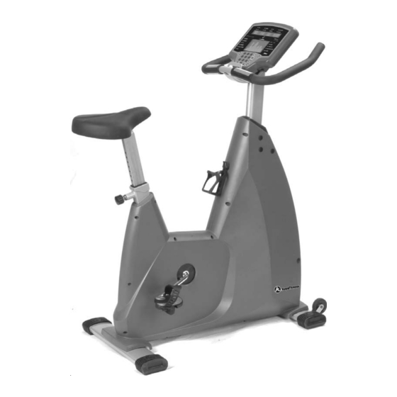
- Page 1 Owner’s Manual Alliance A7 Upright Customer Service (888) 340-0482 Keys Fitness Products 4009 Distribution Drive Suite 250 Garland, TX 75041 www.keysfitness.com Model Name : A7u Serial Number : Write down for future reference. Serial number is located under unit. 315-00011...
-
Page 2: Table Of Contents
Table of Contents Important Safety Information Before You Start Assembly Console Profiles Console Buttons Program Operation Program Profiles Monitoring Your Heart Rate Change to MPH or KPH Bike Operation Parts List Exploded View Warranty Information 12-13 15-16... -
Page 3: Important Safety Information
Important Safety Information WARNING! Before using this unit or starting any exercise program, consult your physician. This is especially important for persons over the age of 35 and/or persons with pre-existing health problems. The manufacturer or distributor assumes no responsibility for personal injury or property damage sustained by or through the use of this product. -
Page 4: Before You Start
Before You Start Thank you for purchasing the Alliance A7 Upright! This quality product you have chosen was designed to meet your needs for cardiovascular exercise. Before you start, please read the Owner's Manual and become familiar with the operation of your new unit. Remember to take the time to perform the stretching exercises provided to avoid injury. -
Page 5: Assembly
Assembly INSTRUCTIONS FOR ASSEMBLY Unpack the box in a clear area. Check to make sure all components are present and in good condition. Do not dispose of the packing material until the assembly is completed. Tools have been provided for you to use when assembling this product. - Page 6 Assembly Step 1 (Figure 1) Attach Rear Stabilizer (D1) to Main Frame (A1) using two Flat Washers (C9), two Spring Washers (C10), and two Hex Nuts (C11). Figure 2 Figure 1 Step 2 (Figure 2) Attach Front Stabilizer (C1) to Main Frame (A1) using two Flat Washers (C9), two Spring Washers (C10), and two Hex Nuts (C11).
- Page 7 Assembly Step 3 (Figure 3) A) Connect Upper Wire Harness (H8) to Lower Wire Harness (A39). Note: Upper Wire Harness will be located inside the Console Tube (H1). B) Slide Console Tube (H1) into Main Frame (A1) and secure using four Flat Allen Head Bolts (H7).
- Page 8 Assembly Step 5 (Figure 5) Attach Seat Pad (E1) to Seat Post (E2). Step 6 (Figure 6) Figure 6 Slide Seat Post (E2) into Main Frame (A1) and secure using Locking Pop Pin Knob (E4). Figure 5...
-
Page 9: Assembly
Assembly Step 7 (Figure 7) A) Thread Right Pedal (A14) into the right crank on Main Frame (A1) by turning the threads Clock-Wise. Note: The Right Pedal is Marked with an R.. B) Thread Left Pedal (A14) into the left crank on Main Frame (A1) by turning the threads Counter Clock-Wise. -
Page 10: Console Profiles
Console Profiles The Alliance A7r has an internal generator that provides electrical power to console display. You never need batteries or have to plug it in. Just simply pedal over 25 RPM to activate the console. There are 3 options for accessing programs: 1. -
Page 11: Console Buttons
Console Buttons QUICK START: Press this button to enter MANUAL program. AT TEST: Press this button to enter AT TEST mode. RESET: Clears current setup variables and goes back to the beginning of setup mode. PAUSE / RESUME: Save and readout the data of current workout situation. ENTER: Confirm the input data for age, weight, program mode, resistance level, and workout time. -
Page 12: Program Operation
Program Operation Monitoring Heart Rate: Heart Rate Handgrips: Place you palms onto the metal sensor plates, after few second your heart rate should be displayed in the window. Heart Rate Transmitter Strap: Adjust the strap to proper length. Wear directly against your skin around chest. -
Page 13: Program Operation
Program Operation HRC Mode: (Heart Rate Control) 1. Use + or - to move the LED Indicator to select one of the following programs: CARDIO, FITNESS TEST, TARGET HEART RATE, OR FAT BURN. You can also use the KEY PAD to choose one directly. 2. -
Page 14: Program Profiles
Program Profiles HRC Programs Cardiovascular: A program designed to keep your workout heart rate value at AT HR x 110%. Fitness Test: A program designed to keep your workout heart rate value at AT HR x 100%. Target Heart Rate: A program designed to keep your workout heart rate value at AT HR x 95%. -
Page 15: Monitoring Your Heart Rate
Monitoring Your Heart Rate Monitoring Your Heart Rate To obtain the greatest cardiovascular benefits from your exercise workout, it is important to work within your target heart rate zone. The American Heart Association (AHA) defines this target as 60%-75% percent of your maximum heart rate. -
Page 16: Monitoring Your Heart Rate
Monitoring Your Heart Rate TARGET HEART RATE ZONE 100% Serious athletic training range Cardiovascular conditioning range Fat burning range... -
Page 17: Change To Mph Or Kph
Change to MPH or KPH Change to MPH (Miles Per Hour) or KPH (Kilometers Per Hour): 1. With the unit off press and hold “0” on the key pad. 2. Start pedaling the bike. “UNIT=KG” OR “UNIT=LB” will be displayed in the upper LED window. 3. -
Page 18: Bike Operation
Bike Operation Seat Adjustment To raise or lower the seat height, start by pulling out the pop pin knob. Next, raise or lower the seat post to the proper position. Then, release the pop pin knob to the pre-set position hole. It is important to ensure that the pop pin knob is locked in one of the pre-set position holes on the seat post. -
Page 19: Parts List
Parts List REF# KEYS PART# DESCRIPTION A7u Frame Assembly 323-00165 310-00123 A7r & A7u Water bottle Holder 302-00311 A7u Seat post bolt A7r & A7u Bearing 331-00038 A7r & A7u Bottom Bracket Set 324-00001 311-00043 A7r & A7u Crank and Pulley set 304-00017 A7u Poly-v Belt 330-00045... -
Page 20: Exploded View
Exploded View... -
Page 21: Warranty Information
Product. To obtain warranty service, you must contact a Keys authorized retailer, service technician or Keys Fitness at our phone numbers located in this manual. Any parts determined to be defective must be returned to Keys to obtain warranty service. You must prepay any shipping charges, export taxes, custom duties and taxes, or any other charges associated with transportation of the parts or Product. - Page 22 Customer Service (888) 340-0482 Keys Fitness Products 4009 Distribution Drive Suite 250 Garland, TX 75041 www.keysfitness.com...