Bryant Evolution Connex SYSTXBBECW01-A Installation Instructions Manual
Evolution connex control
Hide thumbs
Also See for Evolution Connex SYSTXBBECW01-A:
- Owner's manual (52 pages) ,
- Owner's manual (68 pages) ,
- Owner's manual (68 pages)
Table of Contents
Advertisement
Quick Links
SYSTXBBECW01- -A, SYSTXBBECN01- -A
& SYSTXBBECC01- -A
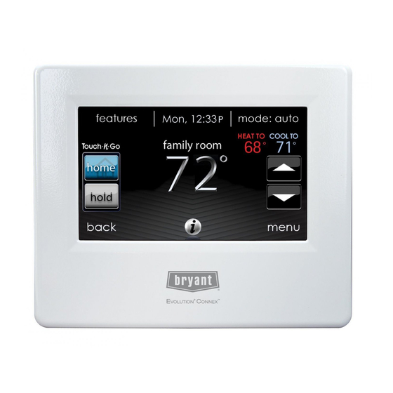
Evolutionr Connext Control
Installation Instructions
NOTE: Read the entire instruction manual before starting the installation.
The features and functions outlined in the Installation Instructions reflect Version 11
software.
See the Evolution Connex product page on the HVACPartner.com
website or the Downloads section of the www.MyEvolutionConnex.Bryant.com
website for the latest software release.
US Patents: Carrier U.S. Pat No. 7,243,004, Carrier U.S. Pat No. 7,775,452, pointSETt U.S.
Pat No. 7,415,102
A12479
Advertisement
Table of Contents

Related Manuals for Bryant Evolution Connex SYSTXBBECW01-A


Summary of Contents for Bryant Evolution Connex SYSTXBBECW01-A
-
Page 1: Installation Instructions
The features and functions outlined in the Installation Instructions reflect Version 11 software. See the Evolution Connex product page on the HVACPartner.com website or the Downloads section of the www.MyEvolutionConnex.Bryant.com website for the latest software release. US Patents: Carrier U.S. Pat No. 7,243,004, Carrier U.S. Pat No. 7,775,452, pointSETt U.S. -
Page 3: Table Of Contents
TABLE OF CONTENTS PAGE 1.Safety Considerations ..........2.Introduction . - Page 4 TABLE OF CONTENTS (cont.) PAGE 4.5. Mounting ..........4.5.1.
- Page 5 TABLE OF CONTENTS (cont.) PAGE 6.Service Menu ........... 6.1.
- Page 6 TABLE OF CONTENTS (cont.) PAGE 6.3.3. Furnace ..........6.3.3.1.Furnace Airflow .
- Page 7 TABLE OF CONTENTS (cont.) PAGE 6.3.4.8.Brownout Disable ........6.3.4.9.Low Air Multiplier .
- Page 8 TABLE OF CONTENTS (cont.) PAGE 6.4.3. Hydronic ..........6.4.4.
- Page 9 TABLE OF CONTENTS (cont.) PAGE 6.5.8. Run/Fault History ........6.5.9.
-
Page 11: Safety Considerations
1. Safety Considerations Improper installation, adjustment, alteration, service, maintenance, or use can cause explosion, fire, electrical shock, or other conditions which may cause death, personal injury or property damage. Consult a qualified installer, service agency or your distributor or branch for information or assistance. The qualified installer or agency must use factory- - authorized kits or accessories when modifying this HVAC system. -
Page 12: Quick Start
When using a Bryant HRV or ERV with a zoned system, the Evolutionr Zone board allows connection of a Bryant HRV or ERV without the need for separate wall control. When using conventional single- - stage outdoor units, the Evolution furnace or fan coil provides the 24 volt signals needed to control them. -
Page 13: 3.1.1. Manually Adjust Time And Date
A14215 3.1.1. Manually Adjust Time and Date To set the HOUR, MINUTE, MONTH, DAY, or YEAR touch the feature you wish to change. Use the Up (Y) and Down (B) buttons to make the appropriate changes. When you have completed all of the settings touch SAVE. A14216... -
Page 14: 3.1.2. Setup Time Zone
3.1.2. Setup Time Zone The time zone can be selected by selecting the setup time zone from the menu. Then select the time zone for the location. Time zones for both US and Canada are included. A14217 3.1.3. Enable Time Synchronization After setting up the time zone, the time synchronization can then be done. -
Page 15: Set Dealer Information
3.2. Set Dealer Information From the main screen, touch MENU, on the bottom of the control. The SERVICE icon allows you to upload your contact information into the Evolution Connex Control. A14274 Format your contact information and logo (if applicable) using the PC/MAC application, save it to a standard USB drive. -
Page 16: Installation
4. Installation 4.1. Overview This instruction covers installation of the Evolutionr Connext Control and the Evolutionr Wireless Access Point only. Physical installation instructions for the indoor and outdoor equipment, and accessories are provided with each unit. Setup, commissioning, operation, and troubleshooting of the Evolutionr System are covered only in this installation instruction. -
Page 17: Location
4.3. Location WARNING ELECTRICAL OPERATION HAZARD Failure to follow this warning could result in personal injury or death. Disconnect power before routing control wiring. All wiring must comply with national, local, and state codes. 4.3.1. Wall Control The Evolution Connex Control is the command center for the Evolution System. It should be located where it is easily accessible and visible to the adult homeowner or end user. -
Page 18: Remote Room Sensors
Close to or in direct airflow from supply registers. In areas with poor air circulation, such as behind a door or in an alcove. 4.3.2. Remote Room Sensors A Remote Room Sensor can be used with the Evolution Connex Control to take the place of the control’s internal temperature sensor. -
Page 19: Smart Sensors (For Zoning Applications)
Damper Control Damper Control Module Module ZS_C Sensor 1 Sensor 2 Sensor 3 Sensor 4 A03233 4.3.3. Smart Sensors (for zoning applications) Any zone may use a Smart Sensor. It provides a temperature display and buttons to adjust the desired temperature in that zone only. It also displays outdoor temperature and indoor humidity sensed at the control. - Page 20 NOTE: ABCD bus wiring only requires a four- - wire connection; however, it is good practice to run thermostat cable having more than four wires in the event of a damaged or broken wire during installation. Each communicating device in the Evolutionr Zone System has a four- - pin connector labeled ABCD.
- Page 21 WARNING ELECTRICAL OPERATION HAZARD Failure to follow this warning could result in personal injury or death. Before installing, modifying, or servicing system, the main electrical disconnect switch must be in the OFF position. There may be more than 1 disconnect switch. Lock out and tag switch with a suitable warning label.
-
Page 22: Shielded Wire
Adjust length and routing of each wire to reach each wire entry on the connector backplate. Strip 1/4- - in (6.4 mm) of insulation from each wire. Match and connect thermostat wires to proper terminals on control backplate. See wiring diagrams in Appendix A. Push any excess wire into the wall. -
Page 23: Damper Control Module
4.4.2. Damper Control Module (zoning systems only) All zoning wiring is run back to the Damper Control Module. Select a location near the furnace or fan coil where wiring from the control, each Remote Room Sensor or Smart Sensor, each damper actuator, and the equipment itself can come together easily. -
Page 24: Decorative Backplate
A12214 A12215 NOTE: Once Evolution Control is secured to wall with the backplate assembly (snapped together), care must be taken not to bend or break the interlocking tabs when removing. 4.5.1. Decorative Backplate Sold separately, a thin decorative backplate is available to hide any marks/screw holes left from the previous thermostat. -
Page 25: Humidifier Connections
A12213 NOTE: Once the Evolution Connex Control is secured to wall with the backplate assembly (snapped together), care must be taken not to bend or break the interlocking tabs when removing. 4.6. Humidifier Connections A 24VAC bypass or fan powered humidifier may be installed. NOTE: Do NOT use a traditional humidistat to control humidifier operation. -
Page 26: Commissioning
automatically energize the HUM output during a call for humidification. The N.O. relay contacts will be used to energize the humidifier. See fan powered humidifier installation instructions for more details. 5. Commissioning This section addresses initial power up (or commissioning) of a new Evolutionr Connex Control. -
Page 27: Searching For Outdoor Unit
A12178 5.2. Searching for Outdoor Unit The Evolution Connex Control will then proceed to communicate with the outdoor unit by displaying “Searching for outdoor unit”. This includes Evolutionr small packaged products (SPP), with UI Version 8.0 software or later. NOTE: If the outdoor unit cannot be found, the control will display “Outdoor unit not found”. -
Page 28: Indoor Evaporator Selection
This selection is used to adequately calculate the refrigerant charge required while in the heat pump charging screens under the Heat Pump Checkout menu (See Pg. 54). Select “other” for non- - Bryant evaporators. 5.4. Electric Heater Selection If the indoor equipment is a fan coil, the control will display “Searching for heater”... -
Page 29: Hydronic Heat Application
A13119 5.4.1. Hydronic Heat Application The Evolution Connex Control supports 2 types of Hydronic Heat applications: 1. Hot water coil in combination with an FE fan coil and heat pump, or hot water coil as sole heat source with an FE fan coil. 2. -
Page 30: Searching Sam Module (If Applicable)
A13117 5.5. Searching for SAM Module (If Applicable) “Searching for SAM Module” will appear on the screen to determine if a System Access Module, used for home automation only, is connected to the system. The SYSTXBBSAM01 is not compatible with this control. The compatible modules are SYSTXBBRCT01 and SYSTXBBRWF01. -
Page 31: Filter Type Selection
A12185 5.7. Filter Type Selection The installer will next be prompted to select the air filter type installed with the Evolution System. After the selection is made, touch NEXT. Air Filter: 1- - in. to 4- - in. media filter EAC: high voltage electronic air cleaner Air Purifier: Evolutionr or Preferredt Air Purifier 5.8. -
Page 32: Airflow Verification Check
selected. If an incorrect selection was made, touch RE- - INSTALL to restart the installation process. Example: SPP Equipment Summary Screen A13127 5.11. Airflow Verification Check The airflow verification check screen will appear next. The system will perform an airflow verification check. This process will take about 1- - 1/2 minutes to complete. When completed, a screen will appear displaying the static pressure (in inches) across the equipment at the expected highest delivered airflow. - Page 33 approximately one minute per zone. The duct assessment will override a call for heat or cool. A duct assessment will automatically occur each day at a user selectable time. The factory default time is 1:00 p.m. but, may be changed by entering the Zoning Setup menu (see pages 45 - - 47).
-
Page 34: Service Menu
6. Service Menu The Service menus contain a set of vital information. This information enables the installer or service person to view a summary of what has been installed, etc. This information is not covered in the Owner’s Manual. To enter service menus, touch menu, then touch and hold the SERVICE icon for at least ten seconds. -
Page 35: Equipment Summary
6.1. Equipment Summary Touch EQUIPMENT SUMMARY to show indoor unit type and model number, outdoor unit type (and model number if a 2- - stage unit), filter type, any accessories that are installed, and the number of zones in the system. To return to the previous screen, touch BACK. -
Page 36: Set Up
A14222 NOTE: For Small Packaged Products (SPP), please use the following instructions for Set- - up (Section 6.3), Checkout (Section 6.4), and Service (Section 6.5): - - For PAC AC Indoor and OAC HP Indoor, follow Fan Coil instructions. - - For Gas PAC Indoor and Gas PHP Indoor, follow Furnace instructions. - - For all PAC Outdoor, follow AC/Heat Pump instructions. -
Page 37: Thermostat
Indoor: Furnace Fan coil PAC AC Indoor PAC HP Indoor GAS PAC Indoor GAS PHP Indoor Outdoor: AC/Heat pump PAC AC outdoor PAC HP outdoor GAS PAC outdoor GAS PHP outdoor Once the equipment has been selected, the appropriate menus will be displayed. 6.3.1. -
Page 38: 1.Auto Mode Set Up
6.3.1.1. Auto Mode set up Once the auto changeover option has been selected, touch SAVE. Enable or Disable: Choose to enable or disable auto changeover mode Default = Enable Auto changeover time: Adjustable from 5 to 120 minutes Default = 30 minutes 6.3.1.2. -
Page 39: 4.Reset Factory Defaults
6.3.1.4. Reset factory defaults This option allows the installer to reset certain factory parameters. After the selections are made, touch SAVE. Program Schedule: Reset back to pre- - programmed time and temperature. User Settings: Reset user settings back to pre- - programmed values. Install Settings: Reset installation settings back to pre- - programmed values. -
Page 40: 1.Airflow
A14223 6.3.2.1. Airflow This option allows the installer to select the appropriate air flow based on the needs of the installation. The QUIET airflow means the minimum cooling airflow that the system can safely run (typically 300 CFM/ton). Use this setting if duct noise is a severe problem. -
Page 41: 2.Altitude
After the selections are made, touch SAVE. Cooling Airflow: Quiet, Comfort, EFF325, EFF350, or Max Default = Comfort Dehumidify Airflow: Normal or High Default = Normal 6.3.2.2. Altitude Static Pressure selection: 0 to 10,000 feet. This is used to correct the static pressure readings the system performs. -
Page 42: 4.Fan Coil G- - Terminal
6.3.2.4. Fan Coil G- - Terminal This setup option selects desired operation when the R to G contact is closed on the fan coil control board. Under this function option, fan turns on fan to selected fan speed when G terminal is energized. Use the alert function to select the contact state for an alert. -
Page 43: 6.Fan Coil G- - Terminal Label
A13230 Shutdown: This setup option selects the change of state required for shutdown. . Select Normally Open or Normally Closed, and then save your selection. A13231 6.3.2.6. Fan Coil G Terminal Alert Label Once the G Terminal Alert label has been entered, it is shown both on the main screen and in the notification email when the alert becomes active. -
Page 44: Furnace
A14224 6.3.3. Furnace First touch SETUP, then touch FURNACE to set up the parameters for the furnace unit. A14225... -
Page 45: 1.Furnace Airflow
6.3.3.1. Furnace Airflow Selects the airflow of the furnace when heating. EFFICIENCY is the airflow used to meet specified ratings, COMFORT is a decreased airflow used to increase the output air temperature and provide increased comfort. For the Low heat rise option, set to ON if the system contains a bypass humidifier. The ON setting will increase the furnace low heat airflow. -
Page 46: 3.Furnace Staging
The dehumidify airflow, when set to NORMAL, the airflow is allowed to adjust to a minimum to satisfy the dehumidification call. When set to HIGH, the minimum airflow during the dehumidify mode is increased to reduce duct and register sweating. Also the airflow increases minimum airflow during normal cooling operation to help reduce duct sweating. -
Page 47: 5.Furnace Off Delay
Min and Max limits are determined by the equipment size. These settings are not the same as the zoning airflow limits. Min. modulating limits: Minimum CFM to run a modulating furnace. This will increase the minimum operating capacity of the furnace. Default value is the furnace air flow for the lowest heat capacity. -
Page 48: 7.Furnace Dehumidifier Drain
6.3.3.7. Furnace Dehumidifier Drain This option selects the time the continuous fan turns off at the end of cooling in order to drain the indoor coil of water. The fan will only be turned off if a dehumidify demand existed at the start of or during the cooling cycle. Dehumidify Drain Time: Adjustable from 5 to 60 minutes Default = 15 minutes 6.3.3.8. -
Page 49: 9.Furnace G Terminal Alert
6.3.3.9. Furnace G- - Terminal Alert Use the alert function to select the contact state for an alert. Select Normally Open or Normally Closed, and then save your selection. A13230 Shutdown: This setup option selects the change of state required for shutdown. . Select Normally Open or Normally Closed, and then save your selection. -
Page 50: Ac/Heat Pump
6.3.4. AC/Heat Pump First touch SETUP, then touch AC/HEAT PUMP to set up the parameters for the AC/Heat Pump unit. A14227 6.3.4.1. Latching High Cool Latch A13227... -
Page 51: 2.Cooling Lockout
System in Control The system will decide which stage should be running to satisfy the cool- ing demand. High Cool Temperature above which only the high stage of cooling will be energized. Only Low Cool The system will only run in low stage cooling. High Heat Latch A13228 System in Control... -
Page 52: 3.Defrost Interval
Cooling Lockout Temp: None, 45, 50 or 55 (_F) Default = None 6.3.4.3. Defrost Interval Time interval at which defrost cycles can occur on a heat pump. AUTO means the defrost interval is optimized by the outdoor control. After the selection is made, touch SAVE. -
Page 53: 6.Ac/Heat Pump Rpm Max
6.3.4.6. AC/Heat Pump RPM Max Used with variable capacity heat pumps, this option clamps the operating speed of the heat pump to this maximum value. Used to reduce operating noise while in high heating capacity. Reducing this value will reduce the heating capacity of the heat pump. -
Page 54: Heat Source Lockout
6.3.5. Heat Source Lockout First touch SETUP, then touch HEAT SOURCE LOCKOUTS to set up the parameters for the AC/Heat Pump unit. For hydronic heat applications, this option allows the installer to set the lockout temperatures below the which only the hydronic coil will operate, and the lockout temperature above which the hydronic coil will not operate. -
Page 55: Zoning (If Applicable)
A14228 6.3.7. Zoning (If Applicable) First touch SETUP, then touch ZONING to set up the parameters for the zoning system (if applicable). A12191 6.3.7.1. Zoning Disable This option allows the installer to enable or disable zoning. After the selection is made, touch SAVE. -
Page 56: 2.Zone Offsets
6.3.7.2. Zone Offsets This option allows actual temperature offset for each zone, allowing calibration (or deliberate miscalibration) of each sensor. Use the Left (<) or Right (>) buttons to change the zone. After the selection is made, touch SAVE. Temperature Offset: Adjustable between - - 5 to 5_F (- - 3 to 3_C) Default = 0_F 6.3.7.3. -
Page 57: Accessories
Duct Assessment Time: Selectable between 12 AM and 11PM Default = 1 PM 6.3.8. Accessories First touch SETUP, then touch ACCESSORIES to set up the parameters for the accessories installed with the system. A12192 6.3.8.1. Filter With this option, the installer has the option of selecting pressure monitoring, the type of filter installed, and the time interval for cleaning. -
Page 58: 2.Humidifier
6.3.8.2. Humidifier With this option, the installer has the option of selecting whether a humidifier is installed, to humidify with the fan in low speed, and the time interval for changing the humidifier pad. After the selections are made, touch SAVE. Humidifier Installed: Yes or No Humidifier selection made during installation;... -
Page 59: Utility Curtailment
6.3.9. Utility Curtailment Utility Saver is used to force the equipment to a lower stage (low or off) when activated by the utility company, typically during peak load times. This setup is available only if the equipment has a utility saver input (refer to outdoor equipment Installation Instructions). -
Page 60: Check Out
A12194 Airflow: Selectable from Off to Max in 50 CFM increments Off = 450 CFM, MAX = (odu_size in KBTU * 400) / 12) Default = Off NOTE: Selected airflow used during hydronic heating is a fixed value, it does not vary. -
Page 61: Electric Heat
A13122 6.4.1. Electric Heat If you have a fan coil with electric heaters, this menu item will allow the heaters to be exercised. With self- - identifying electric heaters, three stages of electric heat are available to be exercised in any combination. Non- - identifying heaters will only provide one stage of heat. -
Page 62: Hydronic
motor turn on, the screen will show the current operating status of the furnace. After the selections are made, touch START. Low Heat: Selectable from 0 to 120 minutes Default = 5 minutes High Heat: Selectable from 0 to 120 minutes Default = 5 minutes 6.4.3. -
Page 63: Heat Pump Heating
High Cool Run Time: Selectable from 0 to 120 minutes Default = 5 minutes 6.4.5. Heat Pump Heating The heat pump heating mode can be exercised with this menu option. With a 2- - stage heat pump, a Low Heat and a High Heat Run Time are independently selectable to exercise. -
Page 64: Heat Pump Cooling
6.4.6. Heat Pump Cooling The heat pump cooling mode can be exercised with this menu option. With a 2- - stage heat pump, a Low Cool Run Time and a High Cool Run Time are independently selectable to exercise. For variable speed heat pumps, you can select the speed at which the heat pump will exercise. -
Page 65: Ventilator
6.4.8. Ventilator The ventilator can be exercised through all of its operating speeds with this menu option. To end the ventilator checkout, touch STOP. Ventilator Check: High, Low or Off 6.4.9. Zoning (If Applicable) This function is not available with the 986T furnace. 6.4.9.1. -
Page 66: 3.Zone Duct Assessment
After proper damper operation has been verified, the installer can now check and verify that each Remote Room Sensor corresponds to the proper zone damper in the same zone. For systems with remote room sensor, temporarily disconnect any other zone Remote Room Sensor (at sensor location). That zone damper will now open, while the Zone 1 damper will close. -
Page 67: Advanced Diagnostics
A13129 6.5.1. Advanced Diagnostics When viewing the Service Information screen, there is a button labeled View Diagnostics, which provides the top 3 most likely root causes for the most recent fault. NOTE: This feature is only available with compatible models. Those models are currently the FE fan coil, the modulating furnace, and the modulating heat pump. -
Page 68: Furnace Status
A12197 6.5.3. Furnace Status The furnace status screen displays relevant information about the furnace operation. To return to the previous screen, touch BACK. To exit the Service menus, touch DONE. A12198 6.5.4. AC Status The AC status screen displays relevant information about the AC operation. To return to the previous screen, touch BACK. -
Page 69: Heat Pump Status
A12199 6.5.5. Heat Pump Status The heat pump status screen displays relevant information about the heat pump operation. To return to the previous screen, touch BACK. To exit the Service menus, touch DONE. A12200 6.5.6. Zoning Status The zoning status screen displays relevant information about the zoning operation. To return to the previous screen, touch BACK. -
Page 70: Last 10 System Events
A12201 6.5.7. Last 10 System Events This screen will show the last 10 events that occurred throughout the system. Each entry has the time and date incident recorded. These events are stored in the memory of the control and are resettable in the THERMOSTAT SETUP screen under the RESET FACTORY DEFAULT selection. -
Page 71: Run/Fault History
6.5.8. Run/Fault History This information is stored in the equipment circuit boards (if communicating) and displayed on the control. The indoor unit and outdoor unit (if communicating) have the following histories. To return to the previous screen, touch BACK. To exit the Service menus, touch DONE. -
Page 72: Service Phone Number
A14230 6.5.10. Service Phone Number This menu item allows the installer to view the name and phone number that the homeowner can call for future service of the system. This name and phone number will appear to the homeowner whenever a service reminder pop- - up message is displayed (i.e. -
Page 73: Refrigerant Charging (Evolution Extreme Only)
6.6. Refrigerant Charging (Evolution Extreme Only) For variable speed heat pumps, a refrigerant charging menu is available to aid in the proper charging of the system. Enter the menu from the service screens by touching REFRIGERANT CHARGING. A12204 6.6.1. Charging Within the CHARGING screens, the installer will have the ability to enter the LINESET length and the VAPOR LINE diameter. -
Page 74: Pump Down
Next, the installer will enter the SERVICE VALVE INFORMATION screen. The current liquid line subcool target, stabilization time, mode and speed in rpm, EXV position in percent, indoor airflow in CFM, outdoor coil temperature in _F, indoor temperature in _F, outdoor temperature in _F, compressor discharge pressure in psig, and accumulator suction pressure in psig are displayed on this screen. -
Page 75: Refrigerant Charging Evolution V
Begin evacuation or refrigerant recovery as required for the procedure after control indicates the EXV is open. Power may be removed from heat pump after the control indicates “READY TO EVACUATE.” 6.7. Refrigerant Charging Evolution V For variable speed heat pumps, a refrigerant charging menu is available to aid in the proper charging of the system. - Page 76 Next, the installer will enter the SERVICE VALVE SUBCOOL screen. This screen will show the current liquid line subcool target (in _F). To begin the charging, touch START. If the outdoor temperatures are not in the required range, Service Valve Subcool may not be available.
-
Page 77: Pump Down
6.7.2. Pump down Because this system has an inverter controlled compressor, suction pressure transducer and EXV, conventional procedure cannot be used to “pump down” and isolate the refrigerant into the outdoor unit. The control has provisions to assist in performing this function. Select mode to pump down in (COOL or HEAT). -
Page 78: Exv Position
PC/MAC software download available www.MyEvolutionConnex.Bryant.com is required to properly format the dealer logo and contact information for use on the wall control. Along with the dealer logo (if any), three lines of dealer information are provided on the wall control:... -
Page 79: Utility Event Setup
The PC/MAC software application to format the dealer logo and contact information can be found at: www.MyEvolutionConnex.Bryant.com/Evolution/downloads Download the program and follow the program instructions. Once the dealer logo and contact information have been properly loaded onto the USB memory device, insert the USB device into the bottom edge of the Evolutionr Connex Control. -
Page 80: 7.0 Wireless Set- - Up
Control with the MyEvolution web and mobile applications is dependent on the compatibility of the user’s computer/network or mobile device, the Evolution Connex Control, and/or the MyEvolution web server with, and the availability of, the user’s Internet service provider or mobile device carrier service. Bryant Heating... -
Page 81: Systxbbecc01- - A Model (Only)
& Cooling Systems makes no representations or warranties, express or implied, including, to the extent permitted by applicable law, any implied warranty of merchantability or fitness for a particular purpose or use, about the compatibility of the user’s computer/network, or mobile device, with the Evolution Connex Control, and/or the MyEvolution web server, with, and the availability of, the user’s Internet service provider or mobile device carrier service, or that the ability to remotely access and adjust the settings of the Evolution Connex Control will not be... - Page 82 A13235 On the next screen look for the SSID of the router/access point. After being selected, it will be outlined in faint blue. Then select NEXT. A13236 The selected network will show. Choose an appropriate Wi- - Fi security. Usually auto- - detect will correctly identify the type of security used. If the network has no security it will show as on the left, but a secured network will prompt for the Wi- - Fi security key.
- Page 83 A13237 If a Wi- - Fi security key is shown as on the right hand picture above then select the white bar and enter the security key, then select NEXT. Touch in the security key area, and the keyboard will appear. Use the on screen keyboard to enter the Wi- - Fi security key, then touch NEXT.
-
Page 84: Systxbbecw01- - A Model (Only)
After the control has connected to the network, go to www.MyEvolutionConnex.Bryant.com to register the unit and begin remote ® access. This requires the MAC address and serial number of the Evolution Connext Wall Control. To find the serial number and MAC address of the ®... - Page 85 A12490 Select the WIRELESS from the menu screen Make sure the Wi- - Fi connection is enabled, by touching ENABLED. Touch SETUP A WI- - FI CONNECTION to begin the process. Next, touch SCAN FOR AVAILABLE ACCESS POINTS. A12115 Select the myHVACxxxxxx connection from the list, then touch NEXT (myHVAC is followed by the last 6 digits of your Wireless Access Point’s MAC address;...
- Page 86 SSID & Security Key A12357 You may have to use the down arrow to scan to the next screen to find “myHVACxxxxxx”. A12116 Use the on screen keyboard to enter the Wi- - Fi security key, then touch NEXT. Touch in the security key area, and the keyboard will appear. The security key can be found on the back of the TP- - LINK Wireless Ac- cess Point.
- Page 87 A12118 After your control has connected to the network, go to www.MyEvolutionConnex.Bryant.com to register the unit and begin remote access. This requires the MAC address and serial number of the EvolutionR Connext Wall Control, NOT the Wireless Access Point. To find the serial number and MAC address of the Evolution Connex Wall Control, click on Menu, Down Arrow, Wireless and View My Evolutionr Info.
- Page 88 If you have any issues, please contact your servicing dealer. When the connection to the MyEvolution web server has been established, the status screen will show Connected fo both Wi- - Fi and the server. TP- - LINK is a trademark of TP- - LINK Technologies Co., Ltd.
-
Page 89: Appendix A - - Wiring Diagrams
8. Appendix A - - Wiring Diagrams Variable-Speed Furnace/ Fan Coil Communicating User Interface AC or H P* Green - Data A Green Yellow - Data B Yellow White - COM White Red - 24VAC Optional Remote Room Sensor ABCD Humidifier Connections Connection... - Page 90 Variable-Speed Furnace/Fan Coil User Interface Green - Data A Yellow - Data B ABCD White - COM Connection Red - 24VAC 1-Spd. Optional Remote Non-Communicating Room Sensor Humidifier Connection Y/Y2 Sensor A12354 Connection Diagram for Furnace or FE Fan Coil with 1- - Stage Air Conditioning...
- Page 91 Variable-Speed Fan Coil User Interface Green - Data A Yellow - Data B ABCD White - COM Connection Red - 24VAC 1-Spd. Optional Remote Non-communicating Room Sensor Humidifier Connection Sensor A12355 Connection Diagram for FE Fan Coil with Non- - communication 1- - Stage Heat Pump...
- Page 92 Indoor Communicating Unit AC or HP Zone Control User Interface & Smart Sensor(s) Green Yellow A B C D White A B C D A B C D Humidifier Connection Damper Control module Sensor (Optional) A04018 Zoning Connection for Communicating Indoor Unit with 2- - Stage Communicating Outdoor Unit...
- Page 93 Indoor Unit Zone Control User Interface & Smart Sensor(s) Green Yellow A B C D White 1-Stage AC A B C D A B C D Humidifier Connection Damper Control Y/Y2 module Sensor A04019 Zoning Connection Diagram for Furnace or FE Fan Coil with Non- - Communicating 1- - Stage Air Conditioning...
- Page 94 Variable-Speed Zone Control Fan Coil User Interface & Smart Sensor(s) Green Yellow A B C D White 1-Spd. HP A B C D A B C D Humidifier Connection Damper Control module Sensor A07149 Zoning Connection diagram for FE Fan Coil with Non- - communicating 1- - Stage Heat Pump...
- Page 95 FE Fan Coil or Variable Speed Furnace A07114 G Input Wiring for Blower Operation...
- Page 96 FE Fan Coil or Variable Speed Furnace A07115 G Input Wiring for System Shutdown...
- Page 97 NOTES...
- Page 98 NOTES (Cont.)
- Page 100 TP- - LINK is a registered trademark of TP- - LINK TECHNOLOGIES CO., LTD. U.S. Export Classification: EAR99. E2014 Bryant Heating & Cooling Systems 7310 W. Morris St. Indianapolis, IN 46231 Edition Date: 03/14 997--- 011280--- 25--- R Catalog No: II---SYSTXBBEC ---05 Manufacturer reserves the right to change, at any time, specifications and designs without notice and without obligations.