
Related Manuals for Muratec F-315


Summary of Contents for Muratec F-315
- Page 1 Muratec MFX-1950/F-315 FACSIMILE SYSTEM FIELD ENGINEERING MANUAL Version 1.0 July 3, 2009 MURATA MACHINERY, LTD COMMUNICATION EQUIPMENT DIV. DA7-91170-60...
-
Page 2: Safety Information
Replace only with the same or equivalent type recommended by the manufacturer. Dispose of used batteries according to the manufacturer’s instructions. Important: Muratec does not recommend the independent replacement of this battery. The battery is sold only as a component part of the main control PCB and Battery... -
Page 3: Table Of Contents
Table of Contents Section 1 General Description ..........1-1 1.1 Product Description ..........................1-1 1.2 Specifications............................1-2 Section2 Machine Composition..........2-1 2.1 Interconnect Block Diagram (1/2) ......................2-1 2.2 Main Control PCB ..........................2-3 2.3 Network Control Unit (NCU) PCB......................2-4 2.4 Power Supply Unit (PSU) ........................2-5 2.5 Sensors..............................2-6 2.5.1 Sensor Locations...........................2-6 2.5.2 Sensor Descriptions ........................2-7... - Page 4 3.13 Print Machine Parameters, Memory Switch and Unique Switch Settings ........3-130 3.14 Factory Functions ...........................3-130 3.14.1 Function List ..........................3-130 3.14.2 LED Test ..........................3-130 3.14.3 LCD Test ..........................3-131 3.14.4 Key Panel Test ........................3-131 3.14.5 SRAM Check...........................3-132 3.14.6 DRAM Check...........................3-132 3.14.7 RTC (real time clock) Test.......................3-133 3.14.8 Page memory check........................3-133 3.14.9 Generate bell test ........................3-133 3.15 Line Tests ............................3-134...
- Page 5 If the original document jams .........................4-5 To remove the document: ........................4-6 If a printout jams inside your machine....................4-8 4.12. The Image Quality Problems ......................4-11 4.12.1 Blank pages..........................4-11 4.12.2 Black pages..........................4-11 4.12.3 Printout too light.........................4-12 4.12.4 Printout too dark ........................4-12 4.12.5 Blurred background ........................4-12 4.12.6 Uneven print density........................4-13 4.12.7 Irregularities..........................4-13 4.12.8 White (Black) Line ........................4-14...
- Page 6 Packaging contents: ..........................6-8 Installation ..............................6-8 6.6 Second phone line kit .........................6-12 Packaging contents: ..........................6-12 Installation ............................6-12 6.7 OfficeBridge Expansion kit (MFX-1950 only)..................6-15 Packaging contents: ..........................6-15 Installation ............................6-15 Setup the OfficeBridge .........................6-17...
-
Page 7: Section 1 General Description
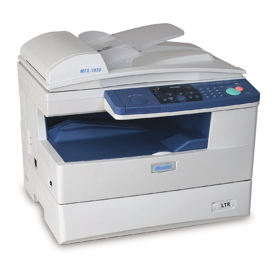
Section 1 General Description 1.1 Product Description The MFX-1950 and F-315 are Multi-function products with flat bed scanner (MFX-1950) and Group 3 and Super G3 modem facsimile machine. Documents are printed on plain paper using dry electrophotographic printing. Automatic Document... -
Page 8: Specifications
US models: 8.2 in. (Fax), 8.5 in. (Copy) for Letter European models: 208 mm (Fax), 210 mm (Copy) for A4 Transmission speed Under 3 seconds (Super G3) Based on transmission of ITU-T Test Document 1 to a Muratec fax machine. Document Memory Standard:... - Page 9 Item MFX-1950 F-315 Printing resolution 600 dpi Printing speed Simplex printing :19 ppm 19 ppm (When loading A4-sized paper (When loading letter or A4-sized from 1st paper cassette.) paper from 1st paper cassette.) Simplex printing :20 ppm (When loading letter paper from 1st paper cassette.)
- Page 10 Item MFX-1950 F-315 Power consumption Europe Energy save mode Standby 23 Wh 24 Wh Memory Transmission 28 W 29 W Reception 1030 W 920 W Copying 1030 W 920 W Maximum 1040 W 940 W × Dimensions 520mm (W) × 450 mm (D)
-
Page 11: Section2 Machine Composition
Section2 Machine Composition 2.1 Interconnect Block Diagram (1/2) 9 May, 2007 Connection Diagram (1/2) Core +3.3VOP +3.3VOP DC/DC DA7-08130-50 VDD3 CONNECT +24VOP +24VOP LED HEAD 135 x 58 /STROBE (Single) DATA1 VDD3 DA7-08450-50 Option DATA2 DATA3 DA7-08100-50 /STROBE DATA4 LINE /HSYNC DATA0 Z90-49754-00... - Page 12 Interconnect Block Diagram (2/2) May 9,2007 Connection Diagram (2/2) Core Core Core Core 52271 +12V (molex) +12V BW/COL PRXD /SAMP PLOAD 20 Characters Z90-37777-50 DCB-70306-50A 2 lines PANEL +24V LSCK DA7-08020-50 ZA1-02394-20 LEDWR1 SCAN-LAMP LEDWR2 330 x 87.5 (ASSY LAMP) 90mm (FFC) (Single)
-
Page 13: Main Control Pcb
2.2 Main Control PCB The main control PCB controls the operations of all machine functions. Jumper JP1 on the main control PCB is used for battery back up of the SRAM. All user programmed data and internal memory switch settings are held in SRAM. Removing JP1 will initialize the SRAM. NOTE: JP1 should remain in the "ON"... -
Page 14: Network Control Unit (Ncu) Pcb
2.3 Network Control Unit (NCU) PCB The NCU PCB provides the connection to the telephone line. It consists of the interface circuit, ring signal detector and telephone control circuit. NCU PCB block diagram for US NCU PCB block diagram for Europe Major components of the NCU DP relay Connects the telephone line to the fax. -
Page 15: Power Supply Unit (Psu)
2.4 Power Supply Unit (PSU) The power supply unit receives the input line voltage and currents it to output voltages of +3.3DVC, +5 VDC and +24 VDC. The heater circuit controls output voltage to the fuser heater according to instructions received from the heater control circuit. -
Page 16: Sensors
2.5 Sensors 2.5.1 Sensor Locations The following illustration shows the relative positions of the machine’s sensors. PES1 JAMC2 OPEN2 PES2 TXIL COVER-SW JAMC1 Thermistor OPEN1 TRAYS... -
Page 17: Sensor Descriptions
2.5.2 Sensor Descriptions The following table gives a brief description of each sensor and its function. Code Name Detects Sensor Type Remarks Document sensor 1 Presence of document in Photo feeder interrupter Document sensor 2 Leading and trailing edge of Photo document interrupter... -
Page 18: Document Scanning Sequence
Feed roller DS2 (Feeler) Press roller Mirror B Home sensor Mirror C Mirror A Mirror A Lens Scanner unit F-315 Pickup roller Separator roller DS1 (Feeler) Separator pad Exit roller Feed roller DS2 (Feeler) Press roller Mirror B Home sensor... -
Page 19: Fbs Section (Mfx-1950 Only)
2.6.1.2 Original Detection The sizes of the documents are detected by the following two sensors; Detection Action Sensor Document presence Detects whether there is a document on the tray or not Leading and trailing edge Detects the leading and trailing edge of detection the feeding document 2.6.2 FBS section (MFX-1950 only) - Page 20 2.6.2.2 Scanner frame Moving Mechanism • During a scan, the scanner frame projects an even amount of light from the Exposure Lamp onto the entire surface of the original. The light is reflected from the original to the Mirror through the lens to the CCD.
-
Page 21: Recording Section
2.7 Recording Section 2.7.1 Recording Paper Feed Path A sheet of the recording paper is separated from the remaining paper by the friction of the pickup roller. The paper is moved along the paper guide until it reaches the register roller. It is then fed by the rotation of the register roller. -
Page 22: Image Processing
2.8 Image Processing Incoming data is received from the telephone line by the NCU and sent to the main control PCB. The modem, located on the main control PCB, demodulates the data. The data is then sent to the printer for image processing. The image processing is roughly divide into the following steps: 1. -
Page 23: Development
2.8.3 Development Toner is applied to the invisible static image on the Drum and a toner image is created on the surface. Toner agitator Drum Developing roller Toner supply roller Part Name Function Toner Agitator Agitates toner. Toner supply Roller Transports the toner to the developing roller. -
Page 24: Erasing
2.8.5 Erasing An LED lamp exposes the Drum surface, when it is exposed the drum charge erases. This helps the drum to be recharged evenly at the next step of charging. Drum LED Lamp 2.8.6 Cleaning The residual toner or paper dust must be removed from the drum. Paper dust is removed from the drum surface by a rubber roller. -
Page 25: Fusing
2.8.7 Fusing An Overview The toner image transferred on to the paper is securely fixed. A heat roller system is used as the fusing system. The toner image is fused by Heater Roller heated by the Heater Lamp, and securely fixed by the pressure between the Heater roller and Press rollers. A Thermistor detects and controls the Heater Roller temperature. -
Page 26: Fusing Temperature Control Circuit
Fusing Temperature Control Circuit The Thermistor detects the surface temperature of the Heater Roller and inputs that analog voltage into the Main Control PCB. Corresponding to this data, the Heater Lamp ON/OFF signal is output to the Heater ON/OFF switch of the power supply unit, causing the Heater Lamp to turn ON or OFF to control the fusing temperature. -
Page 27: Section3 Adjustment Procedures
Section3 Adjustment Procedures 3.1 Field Service Program Modes The fax machine features maintenance modes for machine adjustments. Each mode is listed below along with the command used to activate the mode and a brief functional description. Note: When you press “ * ”, you will hear short beeps. However continue the operation, as there is no problem. - Page 28 Sensor Input test ....................<Menu>, <*>, <2>, <2> Sensor diagnostic test. Printer diagnostic mode ..................<Menu>, <*>, <2>, <3> Printer diagnostic test. Network service mode ..................<Menu>, <*>, <2>, <4> Used to display the server sumcheck or to initialize the network settings, when an optional network board is installed.
-
Page 29: Machine Parameter Adjustment
3.2 Machine Parameter Adjustment 3.2.1 Setting the Machine Parameters These switches are used to program internal machine parameters. The primary back up battery maintains these settings if power is lost. 1. From standby, press <Menu>, <*>,<0>,<0>. Set Parameters / /Enter 2. - Page 30 1 step = 2 / 600 dpi (0.0847 mm) 00000000 0 mm Initial setting Note: These values are 10001000 –0.68 mm factory set and should not be adjusted unless instructed by 10010000 –1.36 mm a Muratec technical representative. 10100000 –2.71 mm –127steps 11111111 –10.76 mm...
- Page 31 Initial setting 10000001 –0.1 % Note: These values are 10000010 –0.2 % factory set and should not be adjusted unless instructed by 10000100 –0.4 % a Muratec technical representative. 10001000 –0.8 % 10001111 –1.5 % Machine Parameter 012 Initial Switch Adjust...
- Page 32 (0.0847 mm) 00000000 15.6 mm 10001000 –0.68 mm Note: These values are factory set and should 10010000 –1.36 mm not be adjusted unless instructed by a Muratec 10010001 –1.44 mm Initial setting technical representative. 10100000 –2.71 mm –127steps 11111111 –10.76 mm...
- Page 33 0 mm Note: These values 10000010 –0.17 mm Initial setting are factory set and should not be adjusted unless 10001000 –0.68 mm instructed by a Muratec technical representative. 10010000 –1.36 mm 10100000 –2.71 mm –127steps 11111111 –10.76 mm Machine Parameter 016...
- Page 34 +0.34 mm Note: These values are factory set and should not be 8 steps 00001000 +0.17 mm adjusted unless instructed by a Muratec technical 00000000 21.85 mm representative. – 8 steps 10001000 – 0.17 mm – 16 steps 10010000 – 0.34 mm –...
- Page 35 +2.82 mm Note: These values 10 steps 00001010 +1.41 mm are factory set and should not be adjusted unless 3 steps 00000011 +0.42 mm instructed by a Muratec 2 steps 00000010 +0.28 mm technical representative. 1 step 00000001 +0.14 mm 00000000 9.15 mm...
- Page 36 Machine Parameter 025 Initial Switch Adjust Usage/Comments Setting Background level adjustment Switch 76543210 Settings starting position 127steps 01111111 +2.70 mm Adjusts the number of the steps from the home sensor 64 steps 01000000 +1.36 mm of the mirror carriage OFF to the background level 32 steps 00100000...
- Page 37 Machine Parameter 030 Initial Switch Adjust Usage/Comments Setting Scanning density level Switch 76543210 adjustment in normal 01111111 Darkest setting resolution. 00001000 00000000 Initial setting 10001000 11111111 Lightest setting Machine Parameter 031 Initial Switch Adjust Usage/Comments Setting Scanning density level Switch 76543210 adjustment in fine resolution.
- Page 38 Machine Parameter 033 Initial Switch Adjust Usage/Comments Setting Scanning density level Switch 76543210 adjustment in hyper–fine 01111111 Darkest setting resolution. 00001000 00000000 Initial setting 10001000 11111111 Lightest setting Machine Parameter 034 Initial Switch Adjust Usage/Comments Setting Scanning density level Switch 76543210 adjustment in hyper–fine 01111111 Darkest setting...
- Page 39 Machine Parameter 090 Initial Switch Adjust Usage/Comments Setting Able to use the bypass tray in When set to “1”, the cassette is not available in fax normal fax reception. reception. 0: Yes 1: No Note: This setting does not affect the rotate fax reception.
- Page 40 Machine Parameter 100 Initial Switch Adjust Usage/Comments Setting Printer registration adjustment (Horizontal) at the See table on page 3-20. 1st cassette for printing. Note: Set this switch after setting the margin to Adjusts the start point to “0 mm” in Unique Switch 52. Then, after setting this print.
- Page 41 Machine Parameter 108 Initial Switch Adjust Usage/Comments Setting Printer registration adjustment (Horizontal) for See table on page 3-20. duplex printing cassette. Note: Set this switch after setting the margin to “0 mm” in Unique Switch 52. Then, after setting this Adjusts the start point to print.
- Page 42 Machine Parameter 140 Initial Switch Adjust Usage/Comments Setting Printer registration adjustment. See table on page 3-20. Adjusts the left margin at the Note: The surrounding margin (right / left / top / 1st cassette for printing. bottom) is set in Unique Switch 52. If you want to adjust only left margin, adjust it in this switch.
- Page 43 Machine Parameter 147 Initial Switch Adjust Usage/Comments Setting Printer registration adjustment. See table on page 3-20. Adjusts the left margin at the Note: The surrounding margin (right / left / top / Bypass tray for printing. bottom) is set in Unique Switch 52. If you want to adjust only left margin, adjust it in this switch.
- Page 44 Machine Parameter 160 Initial Switch Adjust Usage/Comments Setting Printer registration adjustment. See table on page 3-20. Adjusts the right margin at Note: The surrounding margin (right / left / top / the 1st cassette for printing. bottom) is set in Unique Switch 52. If you want to adjust only right margin, adjust it in this switch.
- Page 45 Machine Parameter 167 Initial Switch Adjust Usage/Comments Setting Printer registration adjustment. See table on page 3-20. Adjusts the right margin at Note: The surrounding margin (right / left / top / the Bypass tray for printing. bottom) is set in Unique Switch 52. If you want to adjust only right margin, adjust it in this switch.
- Page 46 Adjusting the print margin Switch(76543210) Settings 01111111 +12.87mm 01111110 +11.52 mm 01100101 +10.84 mm 01100110 +10.16 mm 01011111 +9.48 mm 01011000 +8.81 mm 01010010 +8.13 mm 01001011 +7.45 mm 01000100 +6.77 mm 00111101 +6.10 mm 00110111 +5.42 mm 0011000 +4.74 mm 00101001 +4.06 mm 00010010...
- Page 47 Machine Parameter 180 Initial Switch Adjust Usage/Comments Setting Printer registration Switch 76543210 Settings adjustment (Vertical) at the 1st cassette for printing. 127 steps 01111111 +12.7 mm Adjusts the start point to 32 steps 00100000 +3.2 mm print. 16 steps 00010000 +1.6 mm The plus setting increases the top margin and the minus...
- Page 48 Machine Parameter 187 Initial Switch Adjust Usage/Comments Setting Printer registration Switch 76543210 Settings adjustment (Vertical) at the Bypass tray for printing. 127 steps 01111111 +12.7 mm Adjusts the start point to 32 steps 00100000 +3.2 mm print. 16 steps 00010000 +1.6 mm The plus setting increases the top margin and the minus...
- Page 49 Machine Parameter 220 Initial Switch Adjust Usage/Comments Setting Printer registration Switch 76543210 Settings adjustment. 127 steps 01111111 +12.7 mm Adjusts the top margin at the 1st cassette for printing. 32 steps 00100000 +3.2 mm The plus setting increases 16 steps 00010000 +1.6 mm the top margin and the minus...
- Page 50 Machine Parameter 227 Initial Switch Adjust Usage/Comments Setting Printer registration Switch 76543210 Settings adjustment. 127 steps 01111111 +12.7 mm Adjusts the top margin at the Bypass tray for printing. 32 steps 00100000 +3.2 mm The plus setting increases 16 steps 00010000 +1.6 mm the top margin and the minus...
- Page 51 Machine Parameter 240 Initial Switch Adjust Usage/Comments Setting Printer registration Switch 76543210 Settings adjustment. 127 steps 01111111 +12.7 mm Adjusts the bottom margin at the 1st cassette for printing. 32 steps 00100000 +3.2 mm The plus setting decreases 16 steps 00010000 +1.6 mm the bottom margin and the...
- Page 52 Machine Parameter 247 Initial Switch Adjust Usage/Comments Setting Printer registration Switch 76543210 Settings adjustment. 127 steps 01111111 +12.7 mm Adjusts the bottom margin at the Bypass tray for printing. 32 steps 00100000 +3.2 mm The plus setting decreases 16 steps 00010000 +1.6 mm the bottom margin and the...
- Page 53 Machine Parameter 285 Initial Switch Adjust Usage/Comments Setting Transfer current adjustment When transfer problems occur, adjust this for standard paper front side parameter. Switch 76543210 Settings +3.41 μA 31 steps 00011111 The plus setting increases +0.88 μA the current and the minus 8 steps 00001000 setting decreases it.
- Page 54 Machine Parameter 286 Initial Switch Adjust Usage/Comments Setting Transfer current adjustment When transfer problems occur, adjust this for envelops parameter. Switch 76543210 Settings +3.41 μA 31 steps 00011111 The plus setting increases +0.88 μA the current and the minus 8 steps 00001000 setting decreases it.
- Page 55 Machine Parameter 288 Initial Switch Adjust Usage/Comments Setting Transfer current adjustment When transfer problems occur, adjust this for transparency sheets parameter. (OHP) Switch 76543210 Settings +3.41 μA 31 steps 00011111 +0.88 μA The plus setting increases 8 steps 00001000 the current and the minus 0 μA setting decreases it.
- Page 56 Machine Parameter 460 Initial Switch Adjust Usage/Comments Setting White balance adjustment Switch 76543210 Copy/Black and white scan 16 steps 00010000 + Darkest setting mode Resolution: 600x600dpi 8 steps 00001000 Document type: Text 4 steps 00000100 0 step 00000000 Standard –4 step 10000100 –8 step 10001000...
- Page 57 Machine Parameter 462 Initial Switch Adjust Usage/Comments Setting White balance adjustment Switch 76543210 Copy/Black and white scan 16 steps 00010000 + Darkest setting mode Resolution: 600x600dpi 8 steps 00001000 Document type: Photo/Text Contrast: Normal 4 steps 00000100 0 step 00000000 Standard –4 step 10000100...
- Page 58 Machine Parameter 464 Initial Switch Adjust Usage/Comments Setting White balance adjustment Switch 76543210 Copy mode 16 steps 00010000 + Darkest setting Resolution: 600x300dpi Document type: Text 8 steps 00001000 4 steps 00000100 0 step 00000000 Standard –4 step 10000100 –8 step 10001000 –16step 10010000...
- Page 59 Machine Parameter 466 Initial Switch Adjust Usage/Comments Setting White balance adjustment Switch 76543210 Copy mode 16 steps 00010000 + Darkest setting Resolution: 600x300dpi Document type: Photo/Text 8 steps 00001000 Contrast: Normal 4 steps 00000100 0 step 00000000 Standard –4 step 10000100 –8 step 10001000...
- Page 60 Machine Parameter 468 Initial Switch Adjust Usage/Comments Setting White balance adjustment Switch 76543210 Black and White scan 16 steps 00010000 + Darkest setting Resolution: 300x300 dpi, 200x200dpi 8 steps 00001000 Document type: Text 4 steps 00000100 0 step 00000000 Standard –4 step 10000100 –8 step...
- Page 61 Machine Parameter 470 Initial Switch Adjust Usage/Comments Setting White balance adjustment Switch 76543210 Black and White scan 16 steps 00010000 + Darkest setting Resolution: 300x300 dpi, 200x200dpi 8 steps 00001000 Document type: Photo/Text Contrast: Normal 4 steps 00000100 0 step 00000000 Standard –4 step...
- Page 62 Machine Parameter 472 Initial Switch Adjust Usage/Comments Setting White balance adjustment Switch 76543210 Color scan 16 steps 00010000 + Darkest setting Resolution: All 8 steps 00001000 4 steps 00000100 0 step 00000000 Standard –4 step 10000100 –8 step 10001000 –16step 10010000 Lightest setting The total step is the sum of Machine parameter 472...
- Page 63 Machine Parameter 474 Initial Switch Adjust Usage/Comments Setting White balance adjustment Switch 76543210 Fax mode 16 steps 00010000 + Darkest setting Document type: Normal, Fine, Super fine 8 steps 00001000 4 steps 00000100 0 step 00000000 Standard –4 step 10000100 –8 step 10001000 –16step...
- Page 64 Machine Parameter 476 Initial Switch Adjust Usage/Comments Setting Black balance adjustment Switch 76543210 Copy/Black and white scan 64 steps 01000000 + Darkest setting mode Resolution: 600x600dpi 32 steps 00100000 Document type: Text 16 steps 00001000 8 step 00000100 0 step 00000000 Lightest setting The total step is the sum of Machine parameter 476...
- Page 65 Machine Parameter 478 Initial Switch Adjust Usage/Comments Setting Black balance adjustment Switch 76543210 Copy/Black and white scan mode 64 steps 01000000 + Darkest setting Resolution: 600x600dpi Document type: Photo/Text 32 steps 00100000 Contrast: Normal 16 steps 00001000 8 step 00000100 0 step 00000000 Lightest setting...
- Page 66 Machine Parameter 480 Initial Switch Adjust Usage/Comments Setting Black balance adjustment Switch 76543210 Copy mode 64 steps 01000000 + Darkest setting Resolution: 600x300dpi Document type: Text 32 steps 00100000 16 steps 00001000 8 step 00000100 0 step 00000000 Lightest setting The total step is the sum of Machine parameter 480 and 494 (ADF only).
- Page 67 Machine Parameter 482 Initial Switch Adjust Usage/Comments Setting Black balance adjustment Switch 76543210 Copy mode 64 steps 01000000 + Darkest setting Resolution: 600x300dpi Document type: Photo/Text 32 steps 00100000 Contrast: Normal 16 steps 00001000 8 step 00000100 0 step 00000000 Lightest setting The total step is the sum of Machine parameter 482 and 494 (ADF only).
- Page 68 Machine Parameter 484 Initial Switch Adjust Usage/Comments Setting Black balance adjustment Switch 76543210 Black and White scan 64 steps 01000000 + Darkest setting Resolution: 300x300 dpi, 200x200dpi 32 steps 00100000 Document type: Text 16 steps 00001000 8 step 00000100 0 step 00000000 Lightest setting The total step is the sum of Machine parameter 484...
- Page 69 Machine Parameter 486 Initial Switch Adjust Usage/Comments Setting Black balance adjustment Switch 76543210 Black and White scan 64 steps 01000000 + Darkest setting Resolution: 300x300 dpi, 200x200dpi 32 steps 00100000 Document type: Photo/Text Contrast: Normal 16 steps 00001000 8 step 00000100 0 step 00000000...
- Page 70 Machine Parameter 488 Initial Switch Adjust Usage/Comments Setting Black balance adjustment Switch 76543210 Grayscale scan 64 steps 01000000 + Darkest setting Resolution: All 32 steps 00100000 16 steps 00001000 8 step 00000100 0 step 00000000 Lightest setting The total step is the sum of Machine parameter 488 and 495 (ADF only).
- Page 71 Machine Parameter 490 Initial Switch Adjust Usage/Comments Setting Black balance adjustment Switch 76543210 Fax mode 64 steps 01000000 + Darkest setting Document type: Gray scale Contrast: Normal 32 steps 00100000 16 steps 00001000 8 step 00000100 0 step 00000000 Lightest setting The total step is the sum of Machine parameter 489 and 494 (ADF only).
- Page 72 Machine Parameter 493 Initial Switch Adjust Usage/Comments Setting White balance adjustment This parameter changes the white balance for all copy modes, and black and white 600dpi scan For Copy modes and mode. Black and White 600dpi scan To change the settings for Copy/Scan/Fax mode mode respectively, refer to Machine parameters from 460 to 475.
- Page 73 Machine Parameter 494 Initial Switch Adjust Usage/Comments Setting Black balance adjustment This parameter changes the black balance for ADF scanning for all modes except grayscale scan. For ADF scan To change the settings for Copy/Scan/Fax mode Copy/Scan/Fax modes respectively, refer to Machine parameters from 476 (For grayscale scan, refer to 489.
- Page 74 Machine Parameter 495 Initial Switch Adjust Usage/Comments Setting Black balance adjustment This parameter changes the black balance for ADF scanning in grayscale. For ADF scan in grayscale To change the settings for FBS scan, refer to Machine parameter 488. Switch 76543210 64 steps 01000000...
- Page 75 About the white balance and black balance adjustment (Machine parameters 460 to 495) (–16 steps ≤ A+B ≤ 16 steps) White balance adjustment for FBS : A+B (–16 steps ≤ A+B+C ≤ 16 steps) White balance adjustment for ADF : A+B+C Document Machine parameter for white balance Mode...
- Page 76 Machine Parameter 500 Initial Switch Adjust Usage/Comments Setting PCL Personality Switch 76543210 00000001 PCL (Initial setting) 00000010 PCL XL Machine Parameter 501 Initial Switch Adjust Usage/Comments Setting PCL Orientation Switch 76543210 00000000 Portrait (Initial setting) 00000001 Landscape Machine Parameter 502 Initial Switch Adjust...
- Page 77 Machine Parameter 504 Initial Switch Adjust Usage/Comments Setting PCL Paper source Switch 76543210 00000000 Auto (Initial setting) 00000010 Cassette 1 00000011 Cassette 2 00000110 Bypass Tray Machine Parameter 505 Initial Switch Adjust Usage/Comments Setting PCL Default Media Type Switch 76543210 00000000 Plain (Initial setting) 00000001...
- Page 78 Machine Parameter 508~509 PCL Default Font Number Usage/Comments Switch 76543210 76543210 00010000 00000011 Courier (Initial setting) 00010000 00000101 CG Times 00010000 00000110 Letter Gothic 00010000 00010001 CG Omega 00010000 00010100 Coronet 00010000 00010111 Nw Cent Schlbk 00010000 00011111 IT CA vant Gard 00010000 00101100 Clarendon...
- Page 79 Machine Parameter 510~511 PCL Default Symbol Usage/Comments Switch 76543210 76543210 00000000 00000100 ISO 60: Danish/Norwegian 00000000 00001001 ISO 15: Italian 00000000 00001110 ISO 8859/1 Latin 1 00000000 00010011 ISO 11: Swedish 00000000 00010101 ISO 6: ASC ll 00000000 00100101 ISO 4: United Kingdom 00000000 00100110 ISO 69: French...
- Page 80 Invalid combination of font number and symbols SymbolPS Courier Marigold Mincho Windings ZapfChancery Zapf CG Times Albertus Gothic Dingbats LetterGothic Arial P. Mincho CG Omega Symbol P. Gothic Coronet TimesNewRmn NwCentSchlbk CourierPS ITCAvantGard Helvetica Clarendon Palatino Univers ITCBookman AntiqOlive Times Garamond ISO 60: Danish/Norwegian Invalid...
- Page 81 Machine Parameter 516 ~ 517 PCL X Resolution Usage/Comments Switch 76543210 76543210 00000001 00101100 300 dpi 00000010 01011000 600 dpi (Initial setting) Machine Parameter 518 ~ 519 PCL Y Resolution Usage/Comments Switch 76543210 76543210 00000001 00101100 300 dpi 00000010 01011000 600 dpi (Initial setting) Machine Parameter 520 ~ 521 PCL Time–out period Usage/Comments...
- Page 82 Machine Parameter 522~523 PCL Print copies Usage/Comments Switch 76543210 76543210 00000000 00000000 Invalid 00000000 00000001 1 copy (Initial setting) 00000000 00000010 2 copies 00000011 11100111 999 copies Machine Parameter 524 ~ 525 PCL Time–out period (Text–mode) Usage/Comments Switch 76543210 76543210 00000000 00000000 Invalid...
- Page 83 Machine Parameter 532 ~ 533 PCL Characters per inch Usage/Comments Switch 76543210 76543210 00000000 00000000 Invalid 00000000 00000011 Invalid 00000000 00000100 0.4 characters/inch 00000000 00000101 0.5 characters/inch 00000000 01011010 9.0 characters/inch 00000000 01100100 10.0 characters/inch (Initial setting) 00000000 01101110 11.0 characters/inch 00000011 11100111 99.9 characters/inch...
- Page 84 Machine Parameter 540 Initial Switch Adjust Usage/Comments Setting PJL Response (for AS400) 0: Disable 1: Enable Factory use only Factory use only Factory use only Factory use only Factory use only Factory use only End–Off–Line Text Wrap 0: Enable 1: Disable Machine Parameter 541 ~ 543 Factory use only Machine Parameter 544 Initial...
- Page 85 Machine Parameter 546 Initial Switch Adjust Usage/Comments Setting Factory use only Factory use only Factory use only Factory use only Factory use only Factory use only Line Terminate Switch 1 0 CR=CR; LF=LF; FF=FF CR=CR–LF; LF=LF; FF=FF CR=CR; LF=CR–LF; FF=CR–FF CR=CR–LF;...
-
Page 86: Memory Switch Adjustment
3.3 Memory Switch Adjustment 3.3.1 Setting the Memory Switches These switches are used to program internal machine parameters. The primary back up battery maintains these settings if power are lost. 1. From standby, press <Menu>,<*>,<0>,<1>. Set Memory Switch / /Enter 2. - Page 87 Memory Switch 00 – Dialer Initial Switch Adjust Usage/Comments Setting Factory use only Factory use only CED detection condition Sets whether the detection should be strict or not. Normal Strict 350ms 500ms 700ms 1000ms Switch DIS detect time after dialing Sets the time DIS signal is detected after dialing a 0: 55 sec number.
- Page 88 Memory Switch 01 – Dialer Initial Switch Adjust Usage/Comments Setting Factory use only Factory use only DIS detection condition Sets whether the detection should be strict or not. Normal Strict 200ms 300ms 400ms 500ms Switch PBX mode dial pause Sets the number of seconds the machine waits before dialing when memory switch 002, bit 0 is set to PBX mode.
- Page 89 Memory Switch 02 – Dialer Initial Switch Adjust Usage/Comments Setting Factory use only Factory use only Factory use only Factory use only Factory use only Factory use only Factory use only Redial when D.0.7 error [This Switch is for US only] (EUR) occurred When this switch is set to “1”, the machine does not...
- Page 90 Memory Switch 05 – Dialer Initial Switch Adjust Usage/Comments Setting Factory use only Ring signal detect time Set the time that an incoming ring will not be detected after hanging up. (Fax/Tel Ready mode only.) Switch 6 5 4 0 0 0 100 ms 0 0 1 200 ms...
- Page 91 Memory Switch 10 – Transmission Initial Switch Adjust Usage/Comments Setting Busy tone detection Set this switch to “0” if the ring tone of remote unit is 0: No mistaken for a busy signal. 1: Yes Fallback pattern (bps) 2400 4800 7200 9600 12000...
- Page 92 Memory Switch 11 – Transmission Initial Switch Adjust Usage/Comments Setting The time between reception of CFR and transmission of data When CFR and data overlap due to line echo, increase the interval between CFR and data transmission using this switch. 250 ms 500 ms 750 ms 1000 ms Switch 7 Switch 6...
- Page 93 Memory Switch 12 – Transmission Initial Switch Adjust Usage/Comments Setting Factory use only Factory use only Changing the date format of When set to “1”, the machine changes the date the transmitted TTI format of the transmitted TTI from MM:DD:YY, or 0: No vice versa.
- Page 94 Memory Switch 15 – Transmission Initial Switch Adjust Usage/Comments Setting Program individual autodialer Allows individual setting of memory switches 10 as attributes attribute 1, 11 as attribute 2, 12 as attribute 3 and 0: No 13 as attribute 4 when one–touch and speed dial 1: Yes locations are programmed.
- Page 95 Memory Switch 20 – Reception Initial Switch Adjust Usage/Comments Setting Data error rate Determines the allowable number of erred lines out 0: 10% of total lines received in a document. 1: 20% Pause one second after A 2100 Hz CED signal disables echo suppression in sending CED some telephone equipment.
- Page 96 Memory Switch 23 – Reception Initial Switch Adjust Usage/Comments Setting Factory use only V.34 reception Individual setting for V.34 reception. 0: Yes 1: No Factory use only Factory use only Factory use only Factory use only Factory use only Factory use only Memory Switch 24 ∼...
- Page 97 Memory Switch 31 – Modem Initial Switch Adjust Usage/Comments Setting EYE–Q check level at 7200 bps Strict–– – – – – – – – – – – –Lenient EYE–Q check level at 9600 bps Strict – – – – – – – – – – – –Lenient EYE–Q check level at 12000 bps Strict –...
- Page 98 Memory Switch 33 – Modem Initial Switch Adjust Usage/Comments Setting Factory use only Factory use only Factory use only Factory use only Factory use only Factory use only Delete receive echo of CFR Modem will be opened only in high–speed mode. at the receiver side Sets this switch to “1”...
- Page 99 Memory Switch 40 – Scanner Initial Switch Adjust Usage/Comments Setting Factory use only Factory use only Factory use only Factory use only Factory use only Factory use only Factory use only Document TX length limit Setting to unlimited will override document jam 0: 3.6 meters sensing.
- Page 100 Memory Switch 61 – Remote reception Initial Switch Adjust Usage/Comments Setting Factory use only Factory use only Factory use only Factory use only Off-hook / on-hook detect Sets the time interval between the on-hook and off- time hook (or off-hook/on-hook) condition. Switch 3 2 1 0 Time 0 0 0 0...
- Page 101 Memory Switch 62 – Remote reception Initial Switch Adjust Usage/Comments Setting Factory use only Factory use only Factory use only CNG detect in Ans/Fax ready When set to “1”, the machine detects the CNG 0: No signal in Ans/Fax ready. 1: Yes Switch-hook time If the switch hook is quickly depressed and...
- Page 102 Memory Switch 63 – Remote reception and TAD interface Initial Switch Adjust Usage/Comments Setting Adjust silent detection time This switch adjusts the length of silence required for silent detection activation. Switch 7 6 5 4 Time 0 0 0 0 0 sec 0 0 0 1 1 sec...
- Page 103 Memory Switch 64 – Remote reception and TAD interface Initial Switch Adjust Usage/Comments Setting CNG detect period after TAD Sets the period during which CNG is detected after begins recording ICM the TAD begins recording incoming message. Switch 7 6 5 4 Time 0 0 0 0 0 sec...
- Page 104 Memory Switch 65 – Remote reception Initial Switch Adjust Usage/Comments Setting Adjustment of CI detect time Sets the time added to or reduced from the CI detect time. Switch 7 6 5 4 3 Time 1 1 1 1 1 150 msec 1 1 1 0 1 140 msec...
- Page 105 Memory Switch 70 – Operation Initial Switch Adjust Usage/Comments Setting Display error line The number of error lines contained in the received 0: No data will be shown in the LCD. 1: Yes Tonal line monitor Allows fax communication to be heard through the 0: No monitor speaker.
- Page 106 Memory Switch 71 – Operation Initial Switch Adjust Usage/Comments Setting Factory use only Factory use only Print TCR with the original For easy identification, the first page of a document page during memory stored for memory transmission will print along a transmission when the result TCR when the transmission result is NG.
- Page 107 Memory Switch 90 ~ 96 – Factory use only Memory Switch 097 – Other functions Initial Switch Adjust Usage/Comments Setting Day light saving time This switch sets the month when the daylight saving (Summer time) start month time (summer time) begins. Switch 7 6 5 4 Time 0 0 0 0...
- Page 108 Memory Switch 098 ––– Other functions Initial Switch Adjust Usage/Comments Setting Day light saving time This switch sets the month when the daylight saving (Summer time) end month time (summer time) ends. Switch 7 6 5 4 Time 0 0 0 0 March 0 0 0 1 January...
-
Page 109: Clear Programmed Data / User Settings
3.4 Clear Programmed Data / User Settings User programmed information such as autodialer entries, date, time, Transmit Terminal Identifier (TTI), Subscriber ID, etc., are stored in the unit’s Random Access Memory (RAM). A battery back up holes this information, when the power is lost. This function does not clear the machine parameters, memory switches and unique switches. -
Page 110: All Ram Clear
3.5 All RAM Clear The All RAM Clear setting will erase all user programmed information, all documents in memory, and reset the memory switches to factory defaults. This feature may also be used to try and clear a machine malfunction or lock up. If possible, when the All RAM Clear is used to reset a malfunction or lock up, it is advisable to print the machine settings, one–... - Page 111 Attribute 1 – Individual Autodialer Setting (Equivalent to Memory Switch 10) Initial Switch Adjust Usage/Comments Setting Busy tone detection Sets this switch to “0” if the ring tone of remote unit 0: No is mistaken for a busy signal. 1: Yes Fallback pattern (bps) 2400 4800...
- Page 112 Attribute 2 – Individual Autodialer Setting (Equivalent to Memory Switch 11) Initial Switch Adjust Usage/Comments Setting The time between reception of CFR and transmission of data When CFR and data overlap due to line echo, increase the interval between CFR and data transmission using this switch.
- Page 113 Attribute 3 – Individual Autodialer Setting (Equivalent to Memory Switch 12) Initial Switch Adjust Usage/Comments Setting Factory use only Factory use only Changing the date format of When set to “1”, the machine changes the date the transmitted TTI format of the transmitted TTI from MM: DD: YY, or 0: No vice versa.
- Page 114 Attribute 4 – Individual Autodialer Setting (Equivalent to Memory Switch 13) Initial Switch Adjust Usage/Comments Setting ANSam detection During the V8 handshake, if some noise disturbs 0: Yes the handshake and an error occurs, set to “1”. 1: No V.34 transmission Individual setting for V.34 transmission.
-
Page 115: Unique Switch Adjustment
3.7 Unique Switch Adjustment 3.7.1 Setting the Unique Switches These switches are used to program internal machine parameters. The primary back up battery maintains these settings if power is lost. 1. From standby, press <Menu>, <*>, <0>, <4>. Set Uniq Switch / /Enter 2. - Page 116 Unique Switch 00 — Dialer Initial Switch Adjust Usage/Comments Setting Factory use only Congestion tone detection Setting this switch to “0” ignores telephone line 0: No congestion tones. 1: Yes Ring back tone wait time Sets the time until the ring back tone begins after (seconds) answering an incoming call in the Fax/Tel Ready or 3.0 3.3 3.6 3.9...
- Page 117 Unique Switch 10 – Transmission Initial Switch Adjust Usage/Comments Setting Factory use only Factory use only Factory use only Factory use only Including TTI inside the Setting this bit to “0” transmit the document length document added with the TTI. Setting it to “1” transmit the 0: No length including TTI inside the document.
- Page 118 Unique Switch 17 — Transmission Initial Switch Adjust Usage/Comments Setting Factory use only Factory use only Factory use only Factory use only Factory use only Factory use only JBIG transmission Determines if the JBIG transmission is available. 0: No 1: Yes Factory use only Unique Switch 18 –...
- Page 119 Unique Switch 20 – Reception Initial Switch Adjust Usage/Comments Setting Factory use only Factory use only No use Transmit CED signal Determines if sending CED signal. 0: No 1: Yes Pseudo-ring start time Sets the time the pseudo–ring begins after (seconds) answering an incoming call.
- Page 120 Unique Switch 22 – Reception Initial Switch Adjust Usage/Comments Setting Factory use only Factory use only Factory use only Factory use only JBIG reception Determines how documents from the remote fax are 0: No received. 1: Yes Receive the junk fax When the block junk fax feature is set to Mode 2 0: Yes and the fax does not receive the TSI signal from the...
- Page 121 Unique Switch 30 – Modem Initial Switch Adjust Usage/Comments Setting Factory use only Factory use only 3429 baud symbol rate when If the error frame often occurs because of the communicating at V.34 symbol rate is too high, setting this switch to “1” 0: No mask that symbol rate and keep down the 1: Yes...
- Page 122 Unique Switch 32 – Modem Initial Switch Adjust Usage/Comments Setting Factory use only Factory use only Factory use only Factory use only Factory use only ANSam output time The time limit to output the ANSam (A sinewave 0: 3 sec signal at 2100 Hz amplitude–modulated).
- Page 123 Unique Switch 37 – Modem Initial Switch Adjust Usage/Comments Setting Factory use only Factory use only Factory use only The delay before post- If retraining occurs due to the low reception signal message is transmitted level and few delay of the telephone line, it may overlap the second post-message.
- Page 124 Unique Switch 40 – Factory use only Unique Switch 41 – Scanner Initial Switch Adjust Usage/Comments Setting Set the fixed ratio for copy When set to “1”, the ratio will be calculated in detail and the auto ratio in detail automatically according to the document size and 0: No the recording paper size.
- Page 125 Unique Switch 48 – Scanner Initial Switch Adjust Usage/Comments Setting Factory use only Factory use only Leading edge document Switch 5 4 3 2 1 0 Settings margin adjustment upon 0 0 0 0 0 0 0 mm scanning using FBS 0 0 0 0 0 1 1 mm 0 0 0 0 1 0...
- Page 126 Unique Switch 49 – Scanner Initial Switch Adjust Usage/Comments Setting Factory use only Factory use only Trailing edge document Switch 5 4 3 2 1 0 Settings margin adjustment upon 0 0 0 0 0 0 0 mm scanning using FBS 0 0 0 0 0 1 1 mm 0 0 0 0 1 0...
- Page 127 Unique Switch 50 – Printer Initial Switch Adjust Usage/Comments Setting Factory use only Factory use only Factory use only Factory use only Smoothing in H–Fine (400 x Smoothes the data scanned in each resolution 400 dpi) mode mode. 0: No 1: Yes Smoothing in S–Fine (200 x 400 dpi) mode...
- Page 128 Unique Switch 53 — Printer Initial Switch Adjust Usage/Comments Setting Printer density adjustment. Switch 76543210 Settings 00000000 Not available 00000001 Lightest 00000010 00000011 00000100 00000101 Normal Initial setting 00000110 00001001 Darkest 00001011 Not available ↓ Unique Switch 54 ∼ 59 – Factory use only 3-102...
- Page 129 Unique Switch 60 – Remote reception Initial Switch Adjust Usage/Comments Setting Factory use only Factory use only Factory use only Factory use only Factory use only Use numeric keypad on the Determines if using the numeric keypad on the fax using second phone control panel of the fax using the second phone.
- Page 130 Unique Switch 67 – Remote reception and TAD interface Initial Switch Adjust Usage/Comments Setting Factory use only Factory use only No use CNG detection during OGM output in ANS Ready 0: Yes 1: No Number of detection DTMF Sets the number of detection the DTMF during Ans/Fax Ready mode.
- Page 131 Unique Switch 70 – Operation Initial Switch Adjust Usage/Comments Setting Factory use only LCD error message After an error message has printed, the setting of 0: Remains in LCD this switch determines if the error message will 1: Returns to standby remain in the display.
- Page 132 Unique Switch 72 – Operation Initial Switch Adjust Usage/Comments Setting Factory use only Factory use only Factory use only Factory use only Effect charge setting in When this bit is set to “1”, the following available: department mode Input the price rate per page for transmission 0: No Print transmission charge on the department list 1: Yes...
- Page 133 Unique Switch 74 – Operation Initial Switch Adjust Usage/Comments Setting Factory use only Factory use only Factory use only Factory use only Prohibit double registration When set to “0”, the same phone number can be 0: No registered in two or more one–touch keys or speed 1: Yes dial numbers.
- Page 134 Unique Switch 80 ∼ 84 – Factory use only Unique Switch 85 – Miscellaneous Initial Switch Adjust Usage/Comments Setting Factory use only Print/Send the consumable When both bit 0 of Unique SW 72 and 7 of Unique order sheet when the drum is SW 73 is set to “1”, the setting will be reflected to near end this switch.
- Page 135 Unique Switch 96 – Miscellaneous Initial Switch Adjust Usage/Comments Setting Factory use only Multi line setting This switch enables it to set the first and second 0: No line differently. 1: Yes Factory use only Factory use only Factory use only Factory use only Factory use only Factory use only...
-
Page 136: Monitor
3.8 T.30 Monitor In all binary coded facsimile control procedures the HDLC frame structure is utilized. The basic HDLC structure is shown below. Preamble Binary coded infromation Non-stabdard facilities frame(NSF) Called subscriber identification frame (CSI) Digital identification frame (DIS) Facsimili Facsimili Frame Flag... -
Page 137: How To See The Print Out
3.8.3 How to see the print out (Example for fax transmission) 3-111... - Page 138 (Example for fax reception) TxFrame : Signals sent by machine printing T.30 report RxFrame : Signals received from remote machine DATA: Additional 8–bit octet information to clarify facsimile procedures. In the list, the data are in hexadecimal digits. At the top of each data shows the type of the signal. TCF : TCF check sequence PIX : Image data...
- Page 139 NSF, NSC, NSS: NSF, NSC, NSS are nonstandard unit frames. The first three bytes of the FIF are specified by T.30. The subsequent digits are individually determined by the manufacturers. The first byte refers to the country code. The second byte is a spare; it is 00 (hex) presently. The third byte is the manufacturer code. TxFrame RxFrame D A T A 20 00 00 45 00 00 00 00 00 00 00 00 00 00 00 00 00 00 00...
- Page 140 A transmission with PPR signal: The error frame in fax reception is identified using the post–message signal and PPR signal. An example: TxFrame RxFrame D A T A PPS MPS BF 4F 00 00 0F BC F0 00 FF FF FF FF FF FF FF FF FF FF FF FF FF FF FF FF FF FF FF FF FF FF FF FF FF FF FF FF FF Pages Blocks...
-
Page 141: Printer Maintenance Mode
3.9 Printer maintenance mode In case of followings, use this mode. • When you have replaced the Fuser unit and/or Transfer roller. • When “Please Call Service” message appear in the LCD, access this mode to determine the cause of the “Please Call Service”... -
Page 142: Service Report Printing
3.10 Service Report Printing You can print out a report that contains machine’s usage and error history. 3.10.1 Printing the service report 1. Press <Menu>, <*>, <0>, <7>. Service Report ** Printing ** The seven-sheet report will be printed and the machine returns to the standby mode. 3.10.2 Contents of the service report The contents of the report Header: Line... - Page 143 The first page of the report Paper Cassette Status: Paper Supply Device: The device names that supply paper. Paper Release Device: The device names that stack printouts. Items Detail Present setting Whether the device is available or not, if available the supplied paper size or “Paper out”...
- Page 144 The second page of the report System Inside Information: Not used for field service. System History: The latest 10 details, date and time of the following errors • Scanner jam • Printer jam • Service Call error 3-118...
- Page 145 The third page of the report Paper Size and Printed pages: Note: Some paper size may not be available on the machine. Items Detail Paper size The paper used for printing. Copy (Every I/C) The number of pages used for copy. The value in the parenthesis shows the pages using the current drum.
- Page 146 The fourth page of the report # of application copies: The number of times the copy functions are used. Note: Some functions may not be available on the machine. Items Detail Even Mag. Even magnification (100%) copy Alt. Mag. Alternative magnification (enlarged or reduction) copy Combine Combine copy (n-in-1) Repeat...
- Page 147 Function Count: The number of times that advanced fax functions or other functions are used. Note: Some functions may not be available on the machine. Items Detail Prog. One-touch Program one-touch dial function Speed Tx Transmission using the Address Book Group Tx Transmission using the Address Group Macro Program...
- Page 148 The fifth page of the report Scan Pages / Rate: Note: The RADF is not available on the machine. Items Detail Copy The numbers of documents copied and copied times, per ADF, FBS or RADF. The numbers of documents transmitted and transmitted times, per ADF, FBS or RADF.
- Page 149 Scan contrast: Items Detail Copy The numbers of documents copied per contrast. The numbers of documents transmitted per contrast. Scanner The numbers of documents scanned per contrast. # of Scanner Jam: The total number of document jam in each location Communication Info: Items Detail...
- Page 150 The sixth page of the report # of Errors: Number of errors in transmission per G3, ECM and Super G3. 3-124...
- Page 151 The seventh page of the report # of Errors: Number of errors in reception per G3, ECM and Super G3. 3-125...
-
Page 152: Monitor Speaker
3.11 Monitor speaker If you need to monitor the signal of fax communication, turn this mode to On. You can hear the signal sound with machine’s speaker during fax transaction. 1. From standby mode, press <Menu>, <*>, <0>, <8>, < >. Monitor Speaker :On / /Enter 2. -
Page 153: Life Monitor
3.12.1 Life Monitor The life monitor displays the current software version, the total number of pages scanned, printed, and transmitted, the number of drums replaced and the total page count on the current drum. Note: The All RAM Clear setting does not clear the life monitor. To clear, see below. 1. -
Page 154: Printer Test
3.12.2 Printer Test The Printer Test mode offers seven different test patterns as shown below. A: Checkered B: Squares C: Paper Scum D: Halftone E: Halftone2 F: White G: Black H: Ladder I: LED Head Test J: H Pattern Note: DO NOT print the H Pattern, when there is a document in memory. Printing H Pattern with documents in memory may delete them all. -
Page 155: Feeder Test
4. Select the paper size to test. Paper Size :Auto / /Enter Paper Size / /Enter 5. Press < > or < > until the desired size is displayed. 6. Press <Enter>. Pattern ** Printing ** The selected pattern will be printed continuously. 7. -
Page 156: Print Machine Parameters, Memory Switch And Unique Switch Settings
3.13 Print Machine Parameters, Memory Switch and Unique Switch Settings This function instructs the unit to print a list of the machine parameter, memory switch and unique switch settings. The list shows the default and current settings for each. After printing, the unit returns to standby. 1. -
Page 157: Lcd Test
3.14.3 LCD Test This mode displays two test patterns in LCD. 1. Press <Menu>, <*>, <1>, <1>, < > twice, then press <Enter>. LCD Test Pressing <Start>, all dots turn on. Next pressing <Start>, all dots turn off. Finally pressing <Start>, the alphabetical characters are shown on the LCD. ABCDEFGHIJKLMNOPQRST UVWXYZabcdefghijklmn 2. -
Page 158: Sram Check
3.14.5 SRAM Check This mode is used to test the SRAM memory where user programmed parameters such as date, time, TTI, etc are stored. Note: When this test is executed, the unit will perform an All RAM Clear. The All RAM Clear erases all user settings and resets all memory switches, machine parameters and unique switches to factory defaults. -
Page 159: Rtc (Real Time Clock) Test
4. Press <Start>. The machine starts checking and the result (OK/NG) will be shown in the display. For example, if the check area is “0” and one additional memory, you will see: DRAM Check OK:1 NG:2 When the memory is upgraded you will see: DRAM Check OK:123 5. -
Page 160: Line Tests
3.15 Line Tests This mode offers several internal tests and ability to monitor certain unit output functions. Included are relay tests, modem signal output monitoring, and DTMF output monitoring. 3.15.1 Relay Test This mode tests the on/off operation of various relays and switches. 1. - Page 161 Refer to the table below. Note: It may take several moments for output signal to change. Signal Signal None (stop signal) V17_2400_7200_W1_B4 picture date 400 Hz tone V17_2400_7200_W0_B1 picture date 600 Hz tone V17_2400_7200_W4_B1 picture date 1100 Hz tone V17_2400_9600_W1_B0 picture date 1300 Hz tone V17_2400_9600_W1_B1 picture date 2100 Hz tone...
-
Page 162: Dtmf Output Test
3.15.3 DTMF Output Test The DTMF output test permits the unit’s DTMF tones to be monitored. Note: To monitor the tones, an external monitoring device must be connected to the telephone line jack. 1. Press <Menu>, <*>, <1>, <2>. LINE1 / /Enter 2. -
Page 163: Mirror Carriage Transfer Mode
3.16 Mirror Carriage Transfer Mode Important: The machine is shipped with mirror carriage locking plate for protecting the machine’s mirror carriage during shipping. When installing the fax, slide the scanner locking knob back to its unlocking position. Then turn the power on and perform the following: 1. -
Page 164: Consumable Order Sheet
3.17 Consumable order sheet When the drum cartridge is near end of its design life or the toner cartridge is near empty, the machine prints (or transmit) the consumable sheet. Dealer’s fax number Dealer’s name Customer’s name Dealer’s code Place of the customer write his/her Dealer’s telephone number signature Block letter of customer’s signature... -
Page 165: Set Consumable Order Sheet
3.17.1 Set consumable order sheet 1. Clear the junk data, if necessary (see “Clear consumable order sheet,” next page). 2. Press <Menu>, <*>, <1>, <5>. Set Order Sheet / /Enter 3. Press <Enter>. The will show: Dealer Code ;Upper Enter the dealer’s code. The fax number can be up to 10 characters in length. 4. -
Page 166: Clear Consumable Order Sheet
Enter the customer’s phone number. The phone number may be up to 20 characters in length. 12. Press <Enter> to save the customer’s phone number and continue. The LCD will show: Unit.Serial ;Upper Enter the fax machine’s serial number. The number may be up to 18 characters in length. 13. -
Page 167: Dram Clear
3.18 DRAM Clear Note: Perform a DRAM clear whenever a memory upgrade is installed to the unit or the DRAM is replaced. 1. Press <Menu>, <*>, <1>, <6>. DRAM Clear Yes → Enter 2. Press <Enter>. The DRAM will be cleared. Note: To finish the operation without performing initialization, press <Cancel>. -
Page 168: Clear Optional Data
3.20 Clear Optional Data This mode clears all data and all activity journals for Printer controller and second phone line. 1. Press <Menu>, <*>, <1>, <8>. Option Data Initial Yes → Enter 2. Press <Enter>. The optional data will be cleared. Note: To finish the operation without performing initialization, press <Cancel>. -
Page 169: Life Monitor Maintenance
3.22 Life monitor maintenance When you replace the main control PCB, you should register the previous several counter values of the life monitor. 1. Before updating the software or replacing the main control PCB, write down the counter values of the life monitor. -
Page 170: Sensor Input Test
3.23 Sensor input test This mode can confirm the sensor status. When the sensor operates, the value next to sensor name changes 0 to 1. For example, when open the 1st paper cassette, the CAS1:0 change to CAS1:1. 1. Press <Menu, <*>, <2>, <2>. 2. -
Page 171: Printer Diagnostic Mode
3.24 Printer diagnostic mode This mode can confirm the operation of each parts of the printer section. 1. Press <Menu>, <*>, <2>, <3>. Fan Full :OFF Rx Motor :OFF Dup Motor :OFF / /Enter / /Enter / /Enter Clutch 1 :OFF Clutch 2 :OFF... -
Page 172: Multi Line Settings
3.26 Multi Line Settings This setting makes it possible to set the following menu for the optional second line: • Memory Switches • Unique Switches • ECM mode • Dialing Pause • Number of Rings Note: To set the second line, it is necessary that the Unique Switch 96 bit 6 is set to “On (1)” in advance. -
Page 173: Flash Rom Sum Check
3.27 Flash Rom Sum Check This mode allows you to check Sum after the Flash ROM version is updated. 1. Press <Menu>, <*>, <2>, <9>. 2. Press <Enter> The machine displays the Sum check. ROM :CD08 ROM1:5BE6 ROM2:FC62 3. Press <Reset> to return to standby mode. 3-147... -
Page 174: Set Service Report
3.28 Set Service Report 3.28.1 Set the service report If using this feature, you should be enter following items: • Report location 1 and 2 – Where to send the service report • Report format – Select between simple report or detailed report •... -
Page 175: Clear Service Report
9-2. Enter the day and time in 24–hour format when to send the report, and press <Enter>. Monthly 01,00:00 For instance, to send the report every 5th day of the month at 2 pm, press 0 5 1 4 0 0. 10. -
Page 176: Printer Registration Adjustment
The contents of the simple report The simple report contains the following information of the detail report. See 3.10.2 Contents of the service report on page 3-116 for detail. Header Paper Cassette Status: Printer Jam Info Scan Pages / Rate: # of Scanner Jam Communication Info 3.29 Printer registration adjustment... -
Page 177: Quick Initial Settings
3.30 Quick Initial settings At installation of this machine, you should set some parameters according to the following procedures. You can do the following setting with continuously. 1. Initial settings 2. Consumable order sheet settings 3. Service Report settings Note: Before starting the installation settings, clear the memory by pressing <Menu>, <*>, <0>, <2>, <Enter>. -
Page 178: Update The Software
3.31 Update the software To update the software using your PC, you should follow the following steps: 1. Install the update application on your PC 2. Install the USB driver on your PC 3. Update the software using the PC The installation is only necessary for the fist time. -
Page 179: Installing The Usb Driver On The Pc
4. When the installation is completed, click [Finish]. 3.31.2 Installing the USB driver on the PC Install the USB driver to connect the machine and the PC 1. Press <Menu>, <*>, <9>, <8>, <Enter>. (The displayed LCD may differ according to the model and software version.) 1950 USA A0A0A0... - Page 180 4. Select [Install from a list or specific location (Advanced)] and click [Browse]. 5. Select the folder where the USB driver for RomWrite is installed, and click [OK]. Note: The driver is placed on the PC when you have installed the application on the PC. 3-154...
- Page 181 6. Confirm the driver location and click [Next]. 7. Click [Finish] when the following screen appears. 3-155...
-
Page 182: Updating The Software Using The Pc
3.31.3 Updating the software using the PC Important: You cannot update the software in following situations: · The machine is in transmission · The machine is in scanning or in printing · Data are stored in memory In that case, wait until the transmission, scanning or printing ends, or the stored data is transmitted, deleted or whatever and update the software. - Page 183 4. Click [Browse] and designate the ROM data file. 5. Click [Start]. The ROM Writer erases the current program in the fax machine, then writes the new program to the machine. 3-157...
-
Page 184: Error Code
When the job is completed, the following check– sum table appears. 6. Disconnect your PC from the machine. 7. The machine goes to the Start up screen and the ROM update program starts. When the ROM update is completed, the machine reboots. 8. -
Page 185: Convert Dialing Characters In E-Mail Gateway Functions
3.32 Convert dialing characters in e–mail gateway functions Note: This function is available only when the optional network board has been installed. When transmitting on e-mail gateway, the following dialing characters will be converted to certain characters specified here: Pause (/P) Tone (/T) Flash (/F) 1. -
Page 186: Section4 Troubleshooting Procedures
Section4 Troubleshooting Procedures 4.1 Troubleshooting Outline Before troubleshooting a unit check the following: • Is the power cord correctly connected to the machine? • Are the telephone handset and the telephone line cord connected correctly? • Is there paper in the paper cassette? •... -
Page 187: Recording Paper Jam
4.2 Recording Paper Jam Symptom: Recording paper did not exit paper cassette properly or jam occurred in print area. Suggested corrective action: 1. Verify that the recording paper conforms to the type specified for use in the machine, and that has not been damaged or exposed to moisture. -
Page 188: Document Feeder Multi-Feeding Or Skew
4.4 Document Feeder Multi-feeding or Skew Symptom: Two or more pages of a multi-page document are fed at once. The document is fed on the skew. Slight skewing may sometimes occur. Suggested corrective action: 1. Verify that the original documents conform to the specifications designed for use in the machine and they are not damaged in any way. -
Page 189: Cannot Transmit
4.8 Cannot transmit Symptom: The unit will not transmit Suggested corrective action: 1. Verify the telephone line cord is properly installed and plugged into the correct type of wall jack. 2. Check for dial tone at the unit and wall jack. If no dial tone is present at the unit, check the NCU PCB. -
Page 190: Clearing Jammed Paper
4.11 Clearing Jammed Paper If the original document jams 1. If an original document jams in the ADF while scanning the document into the memory for faxing or copying, the LCD will show: Document Jam ContStor Enter/Cancl If you do wish to continue the operation, press <Enter> and proceed to step 2. To abort the operation, press <Cancel>. -
Page 191: To Remove The Document
To remove the document: Jammed in input area 1. Open the ADF cover. 2. Pull the document gently and out of the ADF. Note: If you cannot remove, turn the release knob to remove the jammed document. 3. Close the ADF cover, making sure both sides are snapped down securely. Note: If the original document has become wrinkled or torn, use the Document glass to resend it. - Page 192 Jammed in feed area 1. Open the platen cover. Open the ADF cover and turn the release knob to remove the jammed document. 2. Close the platen cover and the ADF cover. Note: If the original document has become wrinkled or torn, use the Document glass to resend it. The document glass is available only for the MFX-1950.
-
Page 193: If A Printout Jams Inside Your Machine
If a printout jams inside your machine 1. If paper jams occur the LCD will show: Open 1st Side Cover Please remove Paper Follow these procedures to clear the paper jam. If a paper jam occurs during fax reception, the machine will store the received document in the memory and printout them automatically when you have cleared the paper jam. - Page 194 Jammed in fuser area Jammed in paper exit area If the jammed paper was fed a little and you cannot seize it easily: 3. Open the paper cassette. After you pull it out completely, lift the front part of the cassette slightly up to release the cassette from the machine.
- Page 195 5. Close the side cover and insert the paper cassette. Lower the rear part of the cassette to align the rear edge to the slot of the machine, then insert it completely. Removing jammed paper from the bypass tray 1. If the paper is not properly fed into the machine through the bypass tray, the LCD will show: Remove Bypass Paper Open&CloseFrontCover Pull the flapper release lever and pull the paper out of the machine.
-
Page 196: The Image Quality Problems
4.12. The Image Quality Problems The following provides guidelines for troubleshooting the printer engine and actions to be taken. Before removing any portions of the machine or making any internal adjustments, be sure power to the unit is OFF. Suggested corrective actions should be performed in order as listed. Most conditions can be corrected by performing routine preventative maintenance steps. -
Page 197: Printout Too Light
4.12.3 Printout too light Symptom: Printed image is faint or does not print solid. Poor development • The drum cartridge or toner cartridge may be not installed correctly. Install each cartridge correctly. • Replace the Toner cartridge. • Replace the High Voltage Unit. •... -
Page 198: Uneven Print Density
4.12.6 Uneven print density Symptom: Image graduates from dark to light across page. Poor development • The drum cartridge or toner cartridge may be not installed correctly. Install each cartridge correctly. • Replace the Toner cartridge. • Replace the High Voltage Unit. •... -
Page 199: White (Black) Line
4.12.8 White (Black) Line Symptom: White or black strip appears vertically through image. Poor development ABCDE • Replace the Toner Cartridge. Defective Drum ABCDE • Replace the Drum Cartridge. ABCDE Improper charging • Clean the Charge Wire. ABCDE • Replace the Drum Cartridge. ABCDE Improper fusing •... -
Page 200: Lcd Error Messages
4.13 LCD Error Messages Your fax machine’s LCD messages can help you spot problems. LCD error messages (Alphabetic list) What you see on the LCD What it means/What to do All Commands In Use Your fax machine has all of its 99 possible delayed commands (automatic redialing counts as one) stored in memory and cannot accept another. - Page 201 What you see on the LCD What it means/What to do Enter Reduce/Enlarge You tried to copy your document on the paper other than A4, A5 or F4 sized paper using the bypass tray, or the calculated reduction or enlargement ratio is out of the acceptable range (50 – 200 %) when the copy reduction or enlargement ratio is set to “Auto”.
- Page 202 What you see on the LCD What it means/What to do No Drum Unit The drum cartridge is missing or has not been properly installed in your fax machine. Please properly install the drum cartridge. No Number Stored You selected an autodialer, batch box or F-Code box number for which there is no fax (or phone) number programmed.
- Page 203 What you see on the LCD What it means/What to do Protect Doc. Stored A received document was in your fax’s memory when you tried to turn off the security reception passcode. Print the received document from your fax’s memory, then retry the desired operation.
-
Page 204: Error Codes
4.14 Error Codes If an error occurs during a communication, a check message will be printed. The following provides an explanation of the information found on check messages. • A possible solution to the problem • The date and time of the attempted communication •... -
Page 205: Transmission Errors
R.8.1 A compatibility error occurred. R.8.10 Line noise or other problems prevented line probing. R.8.11 The fax machine timed out while waiting for the retrain signal. Transmission errors T.1.1 T1 time-out. The remote fax machine didn’t respond to your machine. This usually occurs during a manual transmission or when an incorrect number was dialed. -
Page 206: Communication Error Messages
Communication Error Messages The error messages on Check Message printouts indicate the following: Here’s a brief summary: Error Message Possible Meanings • Remote machine malfunctioned Check condition of remote fax. • No handshake signals from remote machine • Wrong phone number reached •... -
Page 207: Service Call Error
4.15 Service Call Error When certain machine problems occur these message will appear in the LCD. 4.15.1 Call For Service Symptom: “Call For Service” is in the LCD. Suggested corrective action: 1. Open the platen cover and verify the lamp is on. 2. - Page 208 The errors messages and an explanation of each are outlined below. RX Motor Error Suggested corrective action: 1. Check the connection between RX motor and the Connect A PCB (P90). (See page 2-1.) 2. Verify the RX motor rotates when the power is on. If OK, see step 6. 3.
- Page 209 Developer Error Suggested corrective action: 1. Verify the toner cartridge is set correctly. 2. Check the point of contacts between toner cartridge and Connect A PCB (P86). 3. Check the contact between Connect A PCB (P80C) and the main board. 4.
-
Page 210: Lcd Failure
4.16 LCD Failure Symptom: No display in the LCD. Suggested corrective action: 1. Verify that the power cord is correctly connected and the power switch is ON. 2. Check for a blown fuse or open circuit on the unit’s internal power supply. 3. -
Page 211: Cleaning The Unit
4.18 Cleaning the Unit Use a mild cleaning solution on a lint-free cloth to wipe the machine’s cover, handset and paper cassette tray. Never spray cleaner directly onto the fax machine as the spray could damage components inside the fax. Curing frequent jams in the ADF If you’re having trouble with getting your original documents to feed properly, try this procedure: 1. -
Page 212: Cleaning The Document Glass, Adf Glass And Document Pad
Important: Make sure the cloth doesn’t have any rough areas. Otherwise, it could scratch the glass surface of the FBS. 3. Using the cloth, gently clean the Document glass, ADF glass and the Document pad on the underside of the platen cover. Note: F-315 has no Document glass. Document pad ADF glass ADF glass... -
Page 213: Section5 Maintenance & Adjustment
Section5 Maintenance & Adjustment 5.1 Maintenance schedule ......................5-2 5.2 Re/Disassemble ........................5-3 5.2.1 COVERS........................5-5 5.2.2 PCBS ........................5-15 5.2.3 SCANNING SECTION....................5-24 5.2.4 PRINTER SECTION....................5-42 5.3 Adjustment ........................5-69 5.3.1 Outline of printer registration adjustment ..............5-69 5.3.2 Printer registration mode ..................5-69 5.3.3 Zoom adjustment ......................5-72 5.3.4 Registration.......................5-76 5.3.5 Separation Pressure adjustment ................5-80 5.3.6 Cleaning the Mirror A, B and C.................5-81... -
Page 214: Maintenance Schedule
Parts Name Reference Page Clean Replace MFX-1950 Drum cartridge (US) — 20,000 MFX-1950 Drum cartridge 30,000 (Europe) F-315 Drum cartridge (US) — 20,000 F-315 Drum cartridge (Europe) 20,000 See Operating MFX-1950 Toner cartridge (US) — 16,000 Instructions MFX-1950 Toner cartridge —... -
Page 215: Re/Disassemble
TRAY DOCUMENT ......................5-5 TRAY DOCUMENT ......................5-6 COVER CONNECT......................5-6 COVER PLATEN (MFX-1950 only) ..................5-7 COVER ADF BASE (F-315 only) ..................5-7 COVER TX SIDE B (MFX-1950) ..................5-8 COVER TX SIDE B (F-315) .....................5-9 COVER TX SIDE F (MFX-1950) ..................5-10 COVER TX SIDE F (F-315)....................5-11 COVER FRONT ......................5-12... - Page 216 ADF PERMIT SENSOR (APS) ..................5-38 SENSOR DS1/DS2 ......................5-39 FBS MOTOR (MFX-1950 only) ..................5-40 ASSEMBLING THE FBS MOTOR (MFX-1950 only) .............5-41 5.2.4 PRINTER SECTION....................5-42 SOLENOID........................5-42 CLUTCH (MG) .......................5-42 RX MOTOR ........................5-43 MOTOR DUPLEX......................5-43 SPRING CLUTCH......................5-44 FRAME DRIVE GEARS ....................5-45 ROLLER TRANSFER.....................5-47 ROLLER REGISTER .....................5-48 SENSOR TRAYS ......................5-49 SENSOR JAMC1 ......................5-50...
-
Page 217: Covers
5.2.1 COVERS Cover Platen (page 5-7) Cover top (page 5-13) Cover contact Cover panel (page 5-13) (page 5-17) Cover ADF base (page 5-7) Cover LENS (page 5-19) Cover TOP PPF Cover option Cover front (page 5-12) (page 5-13) (page 5-20) Cover left (page 5-22) Tray exit paper (page 5-12) Cover TX side F (page 5-10) -
Page 218: Tray Document
TRAY DOCUMENT 1. Release the locking tab from the Cover platen. 2. Remove the TRAY DOCUMENT. Tray document COVER CONNECT 1. Remove the Cover connect mounting screw. 2. Disconnect the connector on the PCB CONNECT A. 3. Remove the COVER CONNECT. Note: When reattaching the Cover connect, be careful not to get the harness caught on the Cover shield. -
Page 219: Cover Platen (Mfx-1950 Only)
Cover platen Ground wire Platen hinge COVER ADF BASE (F-315 only) 1. Remove the Cover connect. (See page 5-6) 2. Open the Cover ADF base. 3. Remove the Ground wire, and then remove two Hinge mounting screws. 4. Remove the COVER ADF BASE. -
Page 220: Cover Tx Side B (Mfx)
COVER TX SIDE B (MFX-1950) 1. Open the Cover platen. 2. Remove the Cover TX side B mounting screw. 3. Close the Cover platen. 4. Open the Guide outer. 5. Release two locking tabs, and then remove the COVER TX SIDE B. Cover TX side B Guide outer... -
Page 221: Cover Tx Side B (F)
COVER TX SIDE B (F-315) 1. Open the Cover ADF base. 2. Remove the Cover TX side B mounting screw. 3. Close the Cover ADF base. 4. Open the Guide outer. 5. Release two locking tabs, and then remove the COVER TX SIDE B. -
Page 222: Cover Tx Side F (Mfx)
COVER TX SIDE F (MFX-1950) 1. Open the Cover platen. 2. Remove the Cover TX side F mounting screw. 3. Close the Cover platen. 4. Open the Guide outer. 5. Release the locking tab, and then remove the COVER TX SIDE F. Cover Tx side F Guide outer 5-10... -
Page 223: Cover Tx Side F (F)
COVER TX SIDE F (F-315) 1. Open the Cover ADF base. 2. Remove the Cover TX side F mounting screw. 3. Close the Cover ADF base. 4. Open the Guide outer. 5. Release the locking tab, and then remove the COVER TX SIDE F. -
Page 224: Cover Front
COVER FRONT 1. Open the Cover front. 2. Release two locking tabs, and then remove the COVER FRONT. Cover front TRAY EXIT PAPER 1. Remove the Chassis FBS. (See page 5-32) 2. Remove the Cover left. 3. Remove the Cover front. 4. -
Page 225: Cover Panel (F)
COVER PANEL. Cover top Cover panel COVER PANEL (F-315) 1. Remove the Cover ADF base. (See page 5-7) 2. Remove five Cover top PPF mounting screws, and then remove the Cover top PPF. 3. Remove three Cover panel mounting screws, then release three locking tabs, and then remove the COVER PANEL. -
Page 226: Tray A Mp/Pad Flapper Mp
TRAY A MP/PAD FLAPPER MP 1. Open the Tray A MP. 2. Release two locking tabs, and then remove the TRAY A MP. Tray A MP 3. Peel off the PAD FLAPPER MP. Pad flapper MP 5-14 5-14... -
Page 227: Pcbs
5.2.2 PCBS PCB PANEL 1(See page 5-16) PCB CCD (See page 5-28) PCB INVERTER (See page 5-17) PCB NCL (See page 5-22) PCB CONNECT C(See page 5-23) PCB PSU (See page 5-22) PCB CONNECT A (See page 5-21) PCB MAIN (See page 5-20) PCB CONNECT B(See page 5-21) POWER-SUPPLY (See page 5-21) 5-15... -
Page 228: Pcb Panel
PCB PANEL 1 1. Remove the Cover platen (MFX-1950) or Cover ADF base (F-315). (See page 5-7) 2. Remove the Cover panel. (See page 5-13) 3. Remove six PCB PANEL 1 mounting screws, and then release eight locking tabs. 4. Disconnect the connector on the PCB PANEL 1. -
Page 229: Pcb Inverter (Mfx)
PCB INVERTER (MFX-1950) 1. Open the Cover platen. 2. Remove two Cover contact mounting screws, then release three locking tabs, and then remove the Cover contact. 3. Remove two Cover lens locking snap fits, and four locking tabs, and then remove the Cover lens. Cover contact Cover lens Snap fit... -
Page 230: Pcb Inverter (F)
PCB INVERTER (F-315) 1. Remove the Cover ADF base. (See page 5-7) 2. Remove the Cover top PPF. (See page 5-13) 3. Remove the Cover lens. (See page 5-19) 4. Remove the PCB INVERTER mounting screw, then disconnect two connectors and two locking tabs, and then the PCB INVERTER. -
Page 231: Lamp (F)
Lamp Case lamp Snap fit Frame scanner LAMP (F-315) 1. Remove the Cover ADF base. (See page 5-7) 2. Remove the Cover top PPF. (See page 5-13) 3. Remove the Cover lens. 4. Lift the front of the Frame scanner. -
Page 232: Pcb Main
PCB MAIN 1. Remove the Cover connect and disconnect the connector. (See page 5-6) 2. Remove two Cover option mounting screws, and then remove the Cover option. 3. Remove four Cover shield mounting screws, and then remove the Cover shield. 4. -
Page 233: Pcb Connect B
PCB CONNECT B 1. Remove the PCB MAIN. (See page 5-20) 2. Separate the PCB CONNECT B. PCB MAIN PCB CONNECT B PCB CONNECT A / POWER-SUPPLY 1. Remove the PCB MAIN. (See page 5-20) 2. Disconnect seven connectors on the PCB CONNECT A. 3. -
Page 234: Pcb Psu / Pcb Ncu
PCB PSU / PCB NCU 1. Remove the Cover option. (See page 5-20) 2. Open the Cover front. 3. Remove the Cover left mounting screw, and then remove the Cover left. Cover front Cover left 4. Remove four PCB NCU mounting screws. 5. -
Page 235: Pcb Connect C
PCB CONNECT C 1. Remove the Chassis FBS. (See page 5-32) 2. Remove the Tray exit paper. (See page 5-12) 3. Disconnect the connector and the Film harness. 4. Remove two PCB CONNECT C mounting screws, and then remove the PCB CONNECT C. PCB CONNECT C 5-23 5-23... -
Page 236: Scanning Section
5.2.3 SCANNING SECTION ROLLER SEPARATOR 1. Remove the Cover TX side B. (See page 5-8) 2. Remove one plastic ring. 3. Slide the bearing as shown below. 4. Remove the Gear 40 0.6B. 5. Remove the Shaft separator and then remove the ROLLER SEPARATOR. Note: When removing the Roller separator, be careful not to lose the plastic ring. - Page 237 ROLLER FEED 1. Remove the Guide inner A. (See page 5-35) 2. Remove three Spring P earth mounting screws, and then remove the Spring P earth. 3. Open the Guide inner B. Guide inner A Guide outer Guide inner B Ground wire Spring P earth 4.
- Page 238 5. Lift the Roller feed and slide out as shown below. Then remove the ROLLER FEED. Roller feed Roller feed 5-26 5-26...
- Page 239 ROLLER EXIT 1. Remove the Guide inner A. (See page 5-35) 2 Remove the Spring P earth. (See page 5-255-25) 3. Open the Guide inner B. 4. Remove two E-rings and then remove the Gear 27 0.5 ONE WAY and one bearing. E-ring Gear 27 0.5 ONE WAY Roller exit...
-
Page 240: Frame Scanner (Mfx)
FRAME SCANNER (MFX-1950) 1. Remove Cover platen. (See page 5-7) 2. Remove the Cover top. (See page 5-13) 3. Remove the Cover lens. (See page 5-17) 4. Disconnect the Flat harness from the connector P1 on the PCB CCD. 5. Release two locking tabs, and then remove the Core. Flat harness Core Frame scanner... -
Page 241: Frame Scanner (F)
8. Slide out the Shaft guide as shown below. Then remove the FRAME SCANNER. Shaft guide Frame scanner FRAME SCANNER (F-315) 1. Remove the Cover ADF base. (See page 5-7) 2. Remove the Cover top PPF. (See page 5-13) 3. Remove the Cover lens. (See page 5-18) 4. - Page 242 6. Lift the front of the Frame scanner, and then disconnect the Flat harness on the Frame scanner. Frame scanner Flat harness 7. Remove two Bracket scanner B mounting screws, and then remove the Bracket scanner B. 8. Slide out the Bracket scanner B as shown below. Then remove the FRAME SCANNER. Bracket scanner B Frame scanner 5-30...
-
Page 243: Home Sensor (Hs) (Mfx-1950 Only)
HOME SENSOR (HS) (MFX-1950 only) 1. Remove the Cover platen. (See page 5-7) 2. Remove the Cover top. (See page 5-13) 3. Remove the Frame scanner. (See page 5-28) 4. Remove the Sensor stopper. 5. Remove the tab, and then remove the HOME SENSOR. Sensor stopper Home sensor 5-31... -
Page 244: Chassis Fbs
CHASSIS FBS 1. Remove the Cover connect. (See page 5-6) 2. Remove the Cover option. (See page 5-20) 3. Remove the Cover shield. (See page 5-20) 4. Remove two Cover back mounting screws, and then remove Cover back. 5. Open the Cover jam access. 6. -
Page 245: Adf Motor
ADF MOTOR 1. Remove the Cover TX side B. (See page 5-8, 5-9) 2. Cut the Cable tie. 3. Disconnect the connector. 4. Remove the three Bracket motor ADF mounting screw, and then remove the Bracket motor ADF. ADF motor Bracket motor ADF Cable tie 5 Remove two ADF motor mounting screw, and then remove the ADF MOTOR. -
Page 246: Sensor Txil
Sensor TXIL 1. Remove the cover TX side B. (See page 5-8, 5-9) 2. Remove the bracket motor ADF. (See page 5-33) 3. Remove the Gear 18/55 and the Gear 24/47. TXIL Gear 24/47 Gear 18/55 4. Cut the Cable tie. 5. -
Page 247: Guide Inner A
GUIDE INNER A 1. Remove the Cover TX side F. (See page 5-10, 5-11) 2. Remove the Cover TX side B. (See page 5-8, 5-9) 3. Remove the Ground wire as shown below. 4. Remove two APS bracket mounting screw and then remove the APS bracket. 5. - Page 248 PAD SEPARATOR 1. Remove the Cover TX side B. (See page 5-8, 5-9) 2. Remove the Roller separator. (See page 5-24) 3. Release two locking tabs, and then remove the Cover separator. 4. Remove the PAD SEPARATOR. Cover separator Pad separator 5-36 5-36...
-
Page 249: Adf Drive Gears
ADF DRIVE GEARS 1. Remove the Cover TX side F. (See page 5-10, 5-11) 2. Remove the Cover TX side B. (See page 5-8, 5-9) 3. Remove the Bracket motor ADF. (See page 5-33) 4. Remove the APS bracket. (See page 5-38) 5. -
Page 250: Adf Permit Sensor (Aps)
ADF PERMIT SENSOR (APS) 1. Remove the Cover TX side F. (See pages 5-10, 5-11) 2. Remove the Cover TX side B. (See pages 5-8, 5-9) 3. Remove the Bracket motor ADF mounting screw. (See page 5-33) 4. Remove two APS bracket mounting screws, and then remove the APS bracket. 5. -
Page 251: Sensor Ds1/Ds
SENSOR DS1/DS2 1. Remove the Guide inner A. (See page 5-35) 2. Loosen the Guide inner B mounting screw (A) and open the Guide inner B. 3. Remove the DS1 mounting screw and disconnect the connector on the DS1, then remove the DS1. 4. -
Page 252: Fbs Motor (Mfx-1950 Only)
FBS MOTOR (MFX-1950 only) 1. Remove the Cover platen. (See page 5-7) 2. Remove the Cover top. (See page 5-13) 3. Remove three Bracket motor FBS mounting screws. 4. Remove the Shaft guide, and then remove the spring C FG. 5. -
Page 253: Assembling The Fbs Motor (Mfx-1950 Only)
ASSEMBLING THE FBS MOTOR (MFX-1950 only) 1. Temporarily tighten the three Bracket motor FBS screws. 2. Attach the belt in position. 3. Tighten up the above three screws. FBS motor Belt 5-41 5-41... -
Page 254: Printer Section
5.2.4 PRINTER SECTION SOLENOID 1. Remove the Cover option. (See page 5-20) 2. Remove the Cover shield. (See page 5-20) 3. Remove the Cover back. (See page 5-32) 4. Remove the Bracket solenoid mounting screw, and then remove the Bracket solenoid. 5. -
Page 255: Rx Motor
RX MOTOR 1. Remove the Cover option. (See page 5-20) 2. Remove the Cover shield. (See page 5-20) 3. Remove the Cover back. (See page 5-32) 4. Remove four RX motor mounting screws and disconnect the connector, and then remove the RX MOTOR. -
Page 256: Spring Clutch
SPRING CLUTCH 1. Remove the Cover option. (See page 5-20) 2. Remove the Cover shield. (See page 5-20) 3. Remove the Cover back. (See page 5-32) 4. Remove two Ground wire mounting screw, and then remove the Ground wire. 5. Remove three Stay pickup mounting screw, and then remove the stay pickup. 6. -
Page 257: Frame Drive Gears
FRAME DRIVE GEARS 1. Remove the Cover option. (See page 5-20) 2. Remove the Cover shield. (See page 5-20) 3. Remove the Cover back. (See page 5-32) 4. Remove three Ground wires. 5. Remove five Frame drive mounting screws, and then pull out the Frame drive. 6. - Page 258 11. Remove the Spring clutch. (See page 5-44) 12. Remove the Clutch (MG). (See page 5-42) 13. Remove the Motor duplex. 14. [4] Remove the Gear 59H/19. 15. [5] Remove the Gear 35/19. 16. [6] Remove the Gear 20. 17. [7] Remove the Gear 21. 18.
- Page 259 ROLLER TRANSFER 1. Open the Cover jam access. 2. Remove the Knob lock JAC. 3. Remove four Guide inner mounting screws, and then remove the Guide inner. 4. Disconnect the connector of PCB ERS lamp. Knob lock JAC Guide inner PCB ERS lamp Cover jam access 5.
- Page 260 6. Remove the two Bracket transfer tabs from the back of the Guide inner. 7. Remove the ROLLER TRANSFER. Bracket transfer Roller transfer ANA05 Bracket transfer ROLLER REGISTER 1. Open the Cover jam access. 2. Remove the Knob lock JAC. (See page 5-47) 3.
-
Page 261: Sensor Trays
SENSOR TRAYS 1. Remove the Cover jam access. 2. Separate the Chassis cassette 2nd from the body, and remove the Sensor stopper from behind. 3. Remove the Sensor TRAYS while pulling up the Feeler MP. TRAYS Feeler MP Sensor stopper Chassis cassette 2nd 5-49 5-49... - Page 262 SENSOR JAMC1 1. Remove the Cover option. (See page 5-20) 2. Remove the Cover shield. (See page 5-20) 3. Remove the Cover back. (See page 5-32)_CHASSIS_FBS 4. Open the Cover jam access. 5. Release the tab, and then remove the Sensor JAMC1. JAMC1 Sensor stopper COVER SWITCH...
-
Page 263: Sensor Pss
SENSOR PSS 1. Remove the Cover jam access. 2. Remove the Guide press B mounting screw, and then remove Guide press B while pulling up the Feeler PSS. 3. Release the tab, and then remove the SENSOR PSS. Guide press B Feeler PSS Sensor stopper Sensor PSS... - Page 264 6. Remove the PAD PRESSURE MP. Note: When reattaching the Pad pressure MP, align the notch with the counterpart on the body. Pad pressure MP Guide paper MPDUP PRINTER FUSER 1. Open the Cover jam access. 2. Remove the Ground wire and four Printer fuser mounting screws, and then remove the harness. 3.
- Page 265 SENSOR PDS / DPS Note: Sensor DPS is for duplex model only. 1. Remove the Chassis FBS. (See page 5-32) 2. Remove five Frame upper mounting screws, and then remove the Frame upper. 3. Remove the Sensor stopper and disconnect the connector, and then remove the SENSOR PDS/DPS. Ground wire Sensor DPS Frame upper...
-
Page 266: Roller Pick Up (1St Cst) / (2Nd Cst)
ROLLER PICK UP (1st CST) / (2nd CST) 1. Pull out the Cassette 1st. 2. Remove one plastic ring and bearing. 3. Release the roller tab from the shaft groove, and remove the ROLLER PICK UP. Roller pick up E-ring Cassette 1st PAD PRESSURE (1st CST) / (2nd CST) 1. -
Page 267: Piece Cover Cst (1St Cst Paper Dust)
PIECE COVER CST (1st CST Paper dust) 1. Pull out the Cassette 1st. 2. Remove two Piece cover CST mounting screws, and then remove the PIECE COVER CST. Note: Paper dust is collected in the Piece cover CST. When it is full, empty it. Cassette 1st Piece cover CST SENSOR JAMC2... - Page 268 SENSOR PES2 1. Separate the Chassis cassette 2nd from the Main frame. 2. Pull out the Cassette 2nd. 3. Turn over the Chassis cassette 2nd. 4. Remove the Bracket sensor mounting screw, and then remove the Bracket sensor. 5. Remove the Sensor stopper and connector, and then remove the Sensor PES2. Chassis cassette 2nd PES2 Bracket sensor...
-
Page 269: Plate Frame B (2Nd Cst)
PLATE FRAME B (2nd CST) 1. Separate the Chassis cassette 2nd from the Main frame. 2. Pull out the Cassette 2nd. 3. Remove the Roller feed 2ND. (See page 5-56) 4. Disconnect the connector of Solenoid. 5. Remove two Plate frame B mounting screws, and then remove the PLATE FRAME B. Solenoid Ground wire Plate frame B... -
Page 270: Plate Frame B Gears (2Nd Cst)
PLATE FRAME B GEARS (2nd CST) 1. Separate the Chassis cassette 2nd from the Main frame. 2. Pull out the Cassette 2nd. 3. Remove the Roller feed 2nd. (See page 5-56) 4. Remove the Plate frame B. (See page 5-57) 5. -
Page 271: Spring Clutch (2Nd Cst)
SPRING CLUTCH (2nd CST) 1. Separate the Chassis cassette 2nd from the Main frame. 2. Pull out the Cassette 2nd. 3. Remove the Roller feed 2ND. (See page 5-56) 4. Remove the Plate frame B. (See page 5-57) 5. Remove three Holder gear 2ND mounting screws, and then remove the Holder gear 2ND. 6. - Page 272 SENSOR OPEN2 1. Separate the Chassis cassette 2nd from the Main frame. 2. Pull out the Cassette 2nd. 3. Remove the Roller feed 2ND. (See page 5-56) 4. Remove the Plate frame B. (See page 5-57) 5. Release the tab, and then remove the Sensor OPEN2. Chassis 2nd Sensor stopper OPEN2...
-
Page 273: Roller Feed Duplex A
ROLLER FEED DUPLEX A 1. Remove the Cover jam access. 2. Remove the Guide inner. (See page 5-47) 3. Remove two Guide upper JAC mounting screws, and then remove the Guide upper JAC. Guide upper JAC Cover jam access 4. Remove the Belt duplex from the Gear 20/25P. 5. - Page 274 6. Remove one bearing, and slide out the ROLLER FEED DUPLEX A. Roller feed duplex A Bearing 5-62 5-62...
-
Page 275: Toner Sensor 1, 2 (Ts1, Ts)
TONER SENSOR 1, 2 (TS1, TS2) 1. Remove the Cover front. (See page 5-12) 2. Pull out the Cassette 1st. 3. Release the Knob pressure. 4. Pull out the Toner cartridge. Knob pressure Toner cartridge Cassette 1st 5. Open the Cover jam access. 6. - Page 276 7. Release the locking tab, and then remove the Bracket toner sensor B. Bracket toner sensor B 8. Remove the TS2 mounting screw, and then remove the TS2 TS 2 Bracket toner sensor B 5-64 5-64...
- Page 277 9. Release the locking tab, and then remove the Bracket toner sensor A. Bracket toner sensor A 10. Remove the TS1 mounting screw, and then remove the TS1. Bracket toner sensor A 5-65 5-65...
- Page 278 SENSOR PES1 1. Pull out the Cassette 1st. 2. Using a short screwdriver, remove the Bracket sensor from the bottom (back) of the body. Bracket sensor 3. Remove the Sensor stopper and connector, and then remove the PES1. PES1 Bracket sensor Sensor stopper 5-66 5-66...
- Page 279 SENSOR OPEN1 1. Remove the Cover option. (See page 5-20) 2. Remove the Cover shield. (See page 5-20) 3. Remove the Cover back. (See page 5-32) 4. Remove the Sensor stopper. 5. Disconnect the connector of Sensor, and then remove the Sensor OPEN1. Sensor stopper OPEN1 5-67...
- Page 280 1. Remove the Chassis FBS. (See page 5-32) 2. Open the Cover jam access. 3. Open the Cover front. 4. Remove the Cover left. 5. Remove the Tray paper exit. 6. Remove the Drum cartridge and the case DEV. 7. Disconnect the Film harness of the PCB CONNECT C. 8.
-
Page 281: Adjustment
5.3 Adjustment 5.3.1 Outline of printer registration adjustment 1. Adjust the printer registration of the first cassette. 2. Adjust the scan position and zoom for ADF and FBS. 3. After performing step1 and 2, adjust printer position for each cassette. 5.3.2 Printer registration mode This mode adjusts the print registration for each paper source. -
Page 282: Adjustment Procedure
Printer registration (top) Test pattern H Adjust so that width A on the test pattern Checkered output falls within the following range. Adjustment Tool Setting Range Standard 0 to 12.7 (mm) Machine parameter: 180, 220 (0.1 mm step) 10 ± 1.5 (mm) -12.8 to 12.7 (mm) Machine parameter: 240 (0.1 mm step) - Page 283 Printer registration (side) Test pattern H Adjust so that width A on the test pattern Checkered output falls within the following range. Adjustment Tool Setting Range Standard –12.8 to 12.7 (mm) 10 ± 1.8 (mm) Machine parameter: 100, 140, 160 (0.6773 mm step) Adjustment procedure 1.
-
Page 284: Zoom Adjustment
5.3.3 Zoom adjustment FBS zoom adjustment (Vertical) Note: This is a sample for adjustment using a particular test chart. The difference should be within ± 1.0% of the actual length of A on the test chart. Adjust so that the following specifications are satisfied with the length of A on the test chart. - Page 285 FBS zoom adjustment (Horizontal) Note: This is a sample for adjustment using a particular test chart. The difference should be within ± 1.0 % of the actual length of A on the test chart. Adjust so that the following specification satisfies the length of A on the test chart.
- Page 286 ADF zoom adjustment (Vertical) Note: This is a sample for adjustment using a particular test chart. The difference should be within ± 1.0 % of the actual length of A on the test chart. Adjust so that the following specifications are satisfied with the length of A on the test chart.
- Page 287 ADF zoom adjustment (Horizontal) Note: This is a sample for adjustment using a particular test chart. The difference should be within ± 1.0 % of the actual length of A on the test chart. Adjust so that the following specifications are satisfied with the length of A on the test chart.
-
Page 288: Registration
5.3.4 Registration FBS registration (top) Edge of the paper Test Chart No.2003-01 Note: This adjustment must be made after the adjustments of printer registration (top and side) of the 1st cassette and FBS zoom adjustments (vertical and horizontal) have been made. Standard Adjustment Tool Setting Range... - Page 289 FBS registration (side) Test Chart Edge of No.2003-01 the paper Note: This adjustment must be made after the adjustments of printer registration (top and side) of the 1st cassette and FBS zoom adjustments (vertical and horizontal) have been made. Standard Adjustment Tool Setting Range –...
- Page 290 ADF registration (top) Edge of the paper Test Chart No.2003-01 Note: This adjustment must be made after the adjustments of printer registration (top and side) of the 1st cassette and ADF zoom adjustments (vertical and horizontal) have been made. Standard Adjustment Tool Setting Range –10.76 10.76 (mm)
- Page 291 ADF registration (side) Test Chart Edge of No.2003-01 the paper Note: This adjustment must be made after the adjustments of printer registration (top and side) of the 1st cassette and ADF zoom adjustments (vertical and horizontal) have been made. Standard Adjustment Tool Setting Range –...
-
Page 292: Separation Pressure Adjustment
5.3.5 Separation Pressure adjustment 1. Open the Guide outer. 2. Pick up the Roller separator. 3. Remove the Cover separator. (See page 5-36) Cover separator Roller separator Rotate direction Separation pressure Clockwise Counterclockwise Down 5-80 5-80... -
Page 293: Cleaning The Mirror A, B And C
1. Remove the Cover contact. (See page 5-17) 2. Lift the front of the Frame scanner and remove the Cover lens and Case lamp. For F-315 1. Remove the Cover ADF base. (See page 5-7) 2. Remove the Cover top PPF. (See page 5-13) 3. -
Page 294: Applying The Sheet Document Press (Mfx-1950 Only)
5.3.7 Applying the Sheet Document Press (MFX-1950 only) 1. Open the Cover platen. 2. Peel the separator off the double-coated tape of the Sheet document press. 3. Place the Sheet document press, with the tape upward, on the Pane. 4. Make sure the press edge is 1 mm away from the document reference position of the Cover contact. 5. -
Page 295: Section 6 Options
Section 6 Options CAUTION: This installation should be done by an authorized Muratec technician. 6.1 Memory Upgrade An optional 32 MB document memory upgrade is available. Packaging contents: 1. Memory module (32 MB)..........1 Installation 1. Turn the machine off and unplug the power cord. - Page 296 6. Perform the memory test (“DRAM check”) by the following procedure. 1) Press <Menu>, <*>, <1>, <1>, then use the cursor key to select “DRAM Check”, and then press <Enter>. 2) Use the numeric keys and one-touch keys [01] through [06] to enter Hex code (00 to FF), and press <Start>.
-
Page 297: Second Paper Cassette
6.2 Second paper cassette Packaging contents: 1. Optional paper cassette........1 2. Second cassette back cover......1 3. Screws .............5 4. Paper size label ..........1 Installation 1. Turn the machine off and unplug the power cord. 2. Remove the covers. 1) Remove the connect cover screw and the cover. 2) Unplug the harness that is going through the connect cover. - Page 298 7. Open the first cassette and attach both screws both ends using two screws. 8. Reattach the covers and the harness. 9. Press <Menu>, <2>, <1>, <0>, <1>, <Enter>. 1st Cassette / /Enter 1st Cassette :Ltr / /Enter 10. Press <Enter> to go to the second cassette setting. 2nd Cassette / /Enter 2nd Cassette...
-
Page 299: Page Counter
6.3 Page Counter The mechanical counter shows the total number of pages the machine prints. Note: This device counts up to 999,999 pages. If more pages are printed, the counter resets to zero and begins counting the new pages from that point. Packaging contents: 1. - Page 300 4. Fasten the counter to the machine frame using a screw. 5. Connect the relay cable to the P94 connector on connection board B. 6. Attach the other end of the relay cable to the counter cable. Connection board B Relay cable Counter 7.
-
Page 301: Pcl Printer Controller
6.4 PCL printer controller Packaging contents: 1. PCL printer board ..........1 2. Spacers.............2 3. Screw ...............2 4. CD ..............1 Note: Two screws are included, but only one is required for installation. Installation 1. Turn the power off and unplug the power cord. 2. -
Page 302: Network Interface Board
6.5 Network interface board Packaging contents: 1. Network interface board ........1 2. Secondary power supply .........1 3. Spacer ..............1 4. Screws .............4 5. Ferrite core ............2 6. Label ..............1 Installation 1. Turn the power off and unplug the power cord. 2. - Page 303 5. Release the cable that is taped to the main power supply and connect it to the secondary power supply. 6. Attach the secondary power supply. 7. Reattach the left cover using one screw. 8. Attach a spacer to the main board. 9.
- Page 304 12. Use the nippers to carefully punch out the panel on the option cover. 13. Reattach the covers and the harness. 14. Wind the ferrite core around the LAN cable. 15. Attach the NETWORK label. 16. Connect the LAN cable. N E T 17.
- Page 305 20. Use numeric keys to enter the IP address. IP Address 192.168. 1. 10 21. Press <Enter>. If necessary, change the subnet mask. 22. Press <Enter>. The machine will show other network settings. 23. For now, press <Reset > to return to standby. 24.
-
Page 306: Second Phone Line Kit
6.6 Second phone line kit Packaging contents: 1. Modem PCB .............1 2. NCU PCB ............1 3. Telephone line cable.........1 4. Label ..............4 5. Spacers ............2 6. Screw A ............2 7. Screw B ............4 LINE2 8. Ferrite core ............1 9. Operation manual ..........1 Note: The inclusion of the telephone line cable varies according to countries. - Page 307 4. Attach two spacers to the main board. 5. Attach the Modem PCB to the spacers and screw the right side of the board to the machine frame using two screws. (Screw A) 6. Attach the NCU PCB onto the Main PCB using four screws. (Screw B) 7.
- Page 308 [GBR only] 12. If you want to attach an external phone or an answering machine to the second phone line kit, connect it to the socket as shown below. An external phone or an answering phone 6-14...
-
Page 309: Officebridge Expansion Kit (Mfx-1950 Only)
6.7 OfficeBridge Expansion kit (MFX-1950 only) Packaging contents: 1. OfficeBridge IC chip..........1 2. CompactFlash memory card ......1 3. Setup Disk ............1 (Contains OfficeBridge programs and manuals) Installation 1. Turn the power off and unplug the power cord. 2. Remove the covers. 1) Remove the connect cover screw and the cover. - Page 310 7. Reattach the left cover using one screw. 8. Attach a spacer to the main board. 9. Attach the OfficeBridge board. 10. Attach the board using four screws. 11. Attach a ferrite core to the harness going out from PCB connect B so that the core comes near the PCB.
-
Page 311: Setup The Officebridge
16. Attach the NETWORK label. N E T 17. Reattach the covers and the harness. 18. Attach the “ADDRESS ENTRY” label to the position as shown on the illustration below. (The “Address Entry” label is on the “Soft key label” supplied with the MFP.) Address Entry Setup the OfficeBridge Refer to the "Setup Guide"...