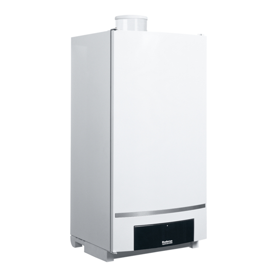
Buderus Logamax plus GB162-80 kW Installation Instructions Manual
Condensing gas boiler
Hide thumbs
Also See for Logamax plus GB162-80 kW:
- Service instructions manual (100 pages) ,
- Installation instructions manual (64 pages) ,
- Instructions manual (16 pages)
Table of Contents
Advertisement
Quick Links
Installation instructions
Logamax plus
GB162-80 kW
GB162-100 kW
CAUTION!
Before putting the boiler into operation read this manual carefully.
WARNING!
Improper installation, adjustment, alteration, service or maintenance
can cause injury, loss of life or property damage. Refer to this manual.
For assistance or additional information consult a qualified installer,
service agency or the gas supplier.
CAUTION!
The operating manual is part of the documentation that is delivered to
the installation's operator. Go through the information in this manual
with the owner/operator and make sure that he or she is familiar with
all the necessary operating instructions.
NOTICE!
In the Commonwealth of Massachusetts this boiler must be installed
by a licensed Plumber or Gas Fitter.
Warning: If the information in these instructions is not
followed exactly, a fire or explosion may result causing
property damage, personal injury or loss of life.
• Do not store or use gasoline or other flammable vapors
and liquids in the vicinity of this or any other appliance.
• What to do if you smell gas
– Do not try to light any boiler.
– Do not touch any electrical switch; do not use any
– Immediately call your gas supplier from a neighbor's
– If you cannot reach your gas supplier, call the fire
• Installation and service must be performed by a quali-
fied installer, service agency or the gas supplier.
Notice!
• This manual is available in the English and French language.
6720645916-00.1N
• This manual must be retained for future reference.
6720645916-000.1N
Condensing gas boiler
phone in your building.
phone. Follow the gas supplier's instructions.
department.
For the registered installer
Please read these
instructions carefully
before starting the
operation
Advertisement
Table of Contents

Related Manuals for Buderus Logamax plus GB162-80 kW


Summary of Contents for Buderus Logamax plus GB162-80 kW
-
Page 1: Installation Instructions
Installation instructions Condensing gas boiler CAUTION! Before putting the boiler into operation read this manual carefully. WARNING! Improper installation, adjustment, alteration, service or maintenance can cause injury, loss of life or property damage. Refer to this manual. For assistance or additional information consult a qualified installer, service agency or the gas supplier. - Page 2 6720645916-01.TD Fig. 1 Logamax plus GB162 with pump group Logamax plus GB162- 80/100 kW - Subject to modifications resulting from technical improvements!
- Page 3 BC10 basic controller receptacle Installation option for room controller, e.g. RC35 Cover with user manual compartment BC10 basic controller, can be expanded e.g. by the RC35 room controller Connection box (low-voltage and 120 VAC connections) Fan harness and mains lead of the pump Condensate drain outlet Condensate collector Boiler front door...
-
Page 4: Table Of Contents
Contents Contents 7.2.1 Installing function modules in the boiler ..29 Guideline to symbols and safety instructions ..6 7.2.2 Installing function modules outside the boiler . . 30 Guideline to symbols ..... . . 6 Electrical wiring diagram . - Page 5 Contents 11.10 Check the air/flue gas connection ... 53 12 Maintenance ....... . . 54 12.1 Prepare the heating system for maintenance .
-
Page 6: Guideline To Symbols And Safety Instructions
Guideline to symbols and safety instructions Guideline to symbols and safety instructions Guideline to symbols DANGER: Warnings if flammable gas explodes. Warnings are indicated in the text by a B Beware if you smell gas: there may be an warning triangle and a gray background. explosion hazard! •... -
Page 7: Safety Instructions
Guideline to symbols and safety instructions Safety instructions • If you cannot reach your gas supplier, call the fire department. The following instructions must be observed • The boiler must only be used for its designated purpose, observing the Installation Instructions. •... -
Page 8: Regulations And Guidelines
Regulations and guidelines Regulations and guidelines • The installation must conform to the requirements of APPROVED CARBON MONOXIDE DETECTORS. Each the authority having jurisdiction or, in the absence of carbon monoxide detector as required in accordance with the above provisions shall comply with NPA 720 and be such requirements, to the National Fuel Gas Code, ANSI/UL 2034 listed and IAS certified. -
Page 9: General Information
These cascade units make installing a cascade system easier and less labor intensive. Please contact Buderus for further information about cascade Pump test systems. If the boiler has not been operational for approx. 2 days,... -
Page 10: Dimensions And Connections
Dimensions and connections Dimensions and connections Without pump group 0.25” (6 mm) 20.5” (520 mm) 16.5" (420 mm) 18.3” (465 mm) 20.5" (520 mm) 6” (152 mm) 4.1” (103.5 mm) 16” (406 mm) 24.8” (630 mm) 1.54” (39 mm) 1.4” (35 mm) 5.1”... -
Page 11: With Pump Group
Dimensions and connections With pump group 16.5" (420 mm) 18.3” (465 mm) 0.25” (6 mm) 20.5” (520 mm) 20.5" (520 mm) 6” (152 mm) 4.1” (103.5 mm) 16” (406 mm) 24.8” (630 mm) 1.4” (35 mm) 1.54” (39 mm) 5.4” (138 mm) 5.1”... -
Page 12: Packaging And Transportation
Packaging and transportation Packaging and transportation Scope of delivery Transporting the boiler The boiler is delivered factory-assembled. CAUTION: The boiler may be damaged • When receiving the delivery, check if the packaging is when it is improperly secured. intact. B Only transport the boiler using the right •... - Page 13 Packaging and transportation 6 720 646157-06.1TD Fig. 6 Incorrect way of lifting and carrying the boiler Logamax plus GB162- 80/100 kW - Subject to modifications resulting from technical improvements!
-
Page 14: Installation
Installation Installation Requirements for the installation NOTICE room B To protect the connection orifice you must not remove the styrofoam bottom DANGER: panel. B Install the heating system in a frost-free B Do not lift the boiler by the door covering room. -
Page 15: Water And Gas Connection
Installation 6 720 646157-10.1TD 6 720 646157-08.1T Fig. 10 Pump group Fig. 8 Aligning the boiler with the set screw pressure relief valve • Level the boiler with the set screw and a spirit level supply water valve (fig. 8, page 15). manual gas shutoff valve circulation pump gas inlet... -
Page 16: Connecting The Pressure Relief Valve (Prv)
Installation • Determine proper size gas pipe for the installation using table 4 and table 5. Do not forget the pipe fitting losses and observe proper size of the fittings • Connect the gas supply pipe to the manual gas shutoff valve, so that it is free from any strain. -
Page 17: Installing The Heating Supply And Return Pipe
6.4.5 Installing the pump pipe Always use the supplied Buderus pump group and the low loss header when installing a single boiler so correct flows are guaranteed. It is not necessary to install a low loss header for cascade systems. -
Page 18: Connecting The Condensate Drain Pipe
Installation • Connect the condensate trap (fig. 14, [1]) to the condensate outlet. The condensate trap has a bayonet connector, insert and turn ¼ rotation clockwise to click into position. 6 720 645916-16.1N Fig. 16 Connecting the condensate trap Condensate trap Air gap >... -
Page 19: Single-Boiler System
Installation WARNING: Boiler Damage! B Boiler must be clear and free from combustible materials, gasoline and other flammable vapors and liquids, and corrosive liquids and vapors. Never use chlorine and hydrocarbon containing chemicals (such as spray chemicals, solution and cleaning agents, paints, glues etc.) in the vicinity of the boiler B Do not store and use these chemicals in... -
Page 20: Flue Gas Adapter
Installation (305 mm) of the top, and one opening shall commence Flue gas adapter within 12" (305 mm) of the bottom of the enclosure. The minimum dimension of air openings shall be not less than 4" (101.6 mm). 1. Where directly communicating with the outdoors, each opening shall have a minimum free area of 1 "... - Page 21 Installation 12" (305 mm) 12" (305 mm) minimum minimum EXHAUST 12" (305 mm) INTAKE minimum 12" (305 mm) 12" (305 mm) minimum minimum 6 720 646916-21.1N 6 720 645916-20.1N Fig. 21 Vent and air pipe position (1) of a sealed combustion Fig.
- Page 22 Installation Approved flue material are from: Roof terminals Flue System (trade name) Supplier 4"/6"(100/150 mm) concentric PVC IPEX Wall terminals Flue System (trade name) Supplier 4" (100 mm) PVC/parallel stainless steel Flex-L/SJTK_DVG 4"/6"(100/150 mm) concentric PVC IPEX 90º-elbow with inlet screen PVC/stainless steel Z-Flex/Heat Fab Tab.
- Page 23 Installation Below are approved examples of vertical and horizontal venting installation NOTICE B Place pipe supports every 5 ft. (1,525 mm) of horizontal and vertical run, beginning with support near boiler. B The condensate must be drained in accordance with the applicable rules. paragraph 6.5 "Connecting the condensate drain pipe", page 18.
- Page 24 Installation 6 720 645916-27.1N Fig. 28 Vertical venting system (non sealed combustion) 6720645916-25.1N Fig. 26 Vertical parallel venting system (sealed combustion) 1 exhaust 4" (102 mm) 2 intake 4" (102 mm) 1 exhaust 4" (102 mm) 3 12" (300 mm) over max. snow level or 24" (600 mm) 2 intake 4"...
-
Page 25: Multiple Boiler Vent Terminal Clearance
Installation Do not exceed the total equivalent venting length of 100 connected to the common venting system are not in feet (30,480 mm) maximum requirement each for the operation: intake and exhaust piping. a) Seal any unused openings in the common venting system. - Page 26 Installation 6 720 645 916-030.1N Fig. 30 Vertical terminations minimum 12" (305 mm) minimum 36" (914 mm) minimum 36" (914 mm) 6 720 645 916-031.1N minimum 12" (305 mm) Fig. 31 Horizontal terminations minimum 36" (915 mm) minimum 24" (610 mm) minimum 12"...
-
Page 27: Electrical Connections
• Route the cable for the low-voltage connections green External heating pump 120 VAC (for use with through the opening on the left (fig. 33, [1]). non Buderus pump group) • Route the cable for the 120 VAC connections through grey DHW tank pump 120 VAC the opening on the left (fig. -
Page 28: Vac Connections
• Connect the external heating or system pump (for (On/Off thermostat) or relay panel end switch to the situations where the pump of the Buderus pump group green WA terminal (fig. 34). The maximum allowed is not used) to the green PK terminal (fig. 35). The resistance of this circuit is 100 Ω... -
Page 29: Controller
Electrical connections 7.1.4 Controller • in the boiler (max. 2), 7.2.1 • outside the boiler, see paragraph 7.2.2. NOTICE B It is not possible to connect more than 7.2.1 Installing function modules in the boiler 1 room controller. The following controls can be connected to the boiler: •... -
Page 30: Installing Function Modules Outside The Boiler
Electrical connections • Click the function module(s) into position in the wall bracket (fig. 39). • Remove the drawer. 6 720 646157-42.1N Fig. 42 Connecting several modules NOTICE B The module may have the letters RC or EMS above the connection (fig. 42, [1]). •... -
Page 31: Electrical Wiring Diagram
Electrical connections • Make an EMS bus connection cable using a 2-core cable and the connector enclosed with the module (fig. 43). Important: Use the connector of the same color as the connections on the module. NOTICE Pay attention to the polarity when using an EMS bus connection cable. - Page 32 Electrical connections Logamax plus GB162-80 kW/-100 kW 120 VAC brown blue green/yellow orange/white blue white green/yellow 120 VAC brown blue grey orange white white/black orange/white blue 120 VAC black black 120 VAC blue brown white brown 120 VAC brown blue...
-
Page 33: Bc10 Basic Controller
Electrical connections Fig. 45 Electrical wiring diagram 81-pole connector (AC 0, 10, 24 and 230 V) 16-pole connector (AC 120 V) Connection for pump in connection kit (accessory) Gas valve Transformer Glow ignitor Earth Ionization Pressure sensor Return sensor Safety-temperature sensor Supply sensor Flue gas sensor Fuse (5 amp. -
Page 34: Operation
The “Service” button is used to display the current space heating water temperature, the current system pressure etc. • Service Tool connection(fig. 47, [5]) For further information please contact Buderus. 6720645916-47.1N Fig. 47 BC10 basic controller • LED “Burner operation”(fig. 47, [6]) The LED “Burner operation”... -
Page 35: Bc10 Operating Instructions
Operation • Space heating water temperature knob(fig. 47, • LED “DHW demand”(fig. 47, [11]) [8]) The LED “DHW status” lights when there is a DHW The Space heating water temperature knob is used to request and is extinguished when the DHW demand is set the upper space heating water temperature limit. - Page 36 Operation Service Mode menu Step 1 Shows currently measured space heating water temperature in °F. paragraph 13.3 "BC10 Display readings", page 57. Step 2 To activate service mode 1 step: Press and hold the d button for more than 2 but not longer than 5 seconds. Step 3 The non-flashing dot is shown in the right-hand bottom corner of the display shows the boiler is now in Flue gas test mode.
- Page 37 Operation Manual Operation menu Step 1 Shows currently measured space heating water temperature in °F. paragraph 13.3 "BC10 Display readings", page Step 2 To activate manual operation: Press and hold the d button for more than 5 seconds. Step 3 A flashing dot in the right-hand bottom corner of the display shows manual operation is active.
-
Page 38: Start-Up Procedure
Start-up procedure Start-up procedure There are several steps involved in starting up the boiler. Complete the commissioning record log book after carrying out all activities described in this chapter. paragraph 15.1 "Start-up report", page 67. FOR YOUR SAFETY READ BEFORE OPERATING WARNING: If you do not follow these instructions exactly, a fire or explosion may result causing property damage, personal injury or loss of life. -
Page 39: Check For Gas Leaks
Start-up procedure Check for gas leaks Prior to the initial start-up check that the gas flow pipe work is gas-tight; this must be confirmed in the start-up report. WARNING: B The boiler and its manual gas shutoff valve must be isolated from the gas supply piping system during any pressure testing of that system, exceeding 0.5 psi (34.5 mbar). -
Page 40: Fill The Condensate Trap With Water
Start-up procedure • Remove the insulation cover of the pump group (fig. 51, step 4) 6720645916-53.1N Fig. 53 Opening the isolating valves (here: open position) 6720645916-51.1N • Read the pressure (PSI) from the pressure gauge on the pump group or on the control panel of the BC10 Fig. -
Page 41: Bleed The Gas Supply Valve
Start-up procedure 6720645916-57.1N Fig. 57 Bleeding the gas flow pipe 6720645916-55.1N Fig. 55 Filling the condensate trap with water • Slowly open the gas valve by pushing on the gas valve and turning it counterclockwise through ¼ rotation WARNING: (fig. 58). The gas valve is open when it is in the vertical Danger of fatal accident due to poisoning. -
Page 42: Checking The Appliance Configuration
Start-up procedure Checking the appliance configuration NOTICE The burner must only be put into use with the correct orifice table 16. B Consult the relevant gas utility company for the type of gas supply. B Check that the actual gas supply is in accordance with the type of gas supply specified on the gas classification label (fig. -
Page 43: Check And Adjust The Gas/Air Ratio
Start-up procedure • Measure the gas supply pressure and enter it in the NOTICE start-up report. paragraph 15.1 "Start-up report", B If the supply pressure is too low, check the page 67. gas supply pipe or contact the relevant To obtain the best preformance of the appliance, the gas gas utility company if the required supply supply pressure must be: pressure is not available. - Page 44 Start-up procedure • Push the fastener down (fig. 51) and open the boiler door. • Open the screw plug on the testing nipple for the burner pressure by 2 turns (fig. 63, [1]). • Set the pressure gauge to "0". NOTICE 5 (Pa) B Throughout the measuring operation, keep...
-
Page 45: Carry Out A Leakage Test In Operating Conditions
Start-up procedure • Press the "Chimney sweep" button (fig. 62, [3]) to clear the reading, table 12, "Flue gas test", page 35. • Check that the boiler performance is still at the required value. table 15, "Settings", page 37. Carry out a leakage test in operating conditions WARNING: Leaks may be caused to pipes and screw... -
Page 46: Measure The Ionization Current
Start-up procedure 9.12 Measure the ionization current • Press on the control panel to open it. • Open at least 2 radiator valves, if present. Do not switch ON the boiler. • Switch OFF the appliance by pressing the main switch of the BC10 basic controller (fig. -
Page 47: Boiler Settings
Start-up procedure • Disconnect the plug and socket connection of the Knob Explanation monitoring cable. position • Switch ON the appliance by pressing the main switch No supply to appliance (e.g. only DHW mode) of the BC10 basic controller (fig. 67, [1]). 86-190 The temperature (in °F) set on the BC10 cannot •... -
Page 48: Final Activities
Start-up procedure Knob Explanation position DHW mode is OFF (only heating mode) Economy mode. The DHW will only be reheated to 140 °F (60 °C), if the temperature has significantly fallen. This reduces the number of burner starts and saves energy. As a result the water may be a bit colder initially. -
Page 49: Shutting Down The System
Shutting down the system 10 Shutting down the system 10.2 Shutting down the heating system if CAUTION: there is a risk of freezing The heating system may freeze if it is not (interruption of use) operational in times of freezing. If conditions are such that the heating system has to be B Protect the heating system against shut down for a long period while there is a risk of... -
Page 50: Inspection
Inspection 11 Inspection Offer your customer an annual inspection and INSTRUCTION FOR THE INSTALLER maintenance contract. The activities to be included in an B If gas pipes have to be disconnected from annual inspection and maintenance contract can be found the gas burner fitting, the burner cover in the inspection and service reports ( paragraph 15.2 must only be opened by a specialized... -
Page 51: Carry Out A Visual Check For General Signs Of Corrosion
Inspection 11.2 Carry out a visual check for general 11.5 Measure the gas inlet pressure signs of corrosion (working pressure) • Check all gas and water-bearing pipes for signs of paragraph 9.7 "Measure the gas inlet pressure corrosion and for leaks. (working pressure)", page 42. -
Page 52: Maintenance
Maintenance 12 Maintenance • Unscrew the bolt from left-hand top hinge of the boiler INSTRUCTION FOR THE INSTALLER door and remove it together with the washer(fig. 79). B Record the activities in the service report • Slightly lift the door and pull it from the hinge. paragraph 15.3 "Service report", •... -
Page 53: Remove The Burner Cover With The Fan And The Gas Valve
Maintenance 6720645916-82.1N Fig. 82 Pulling the air suction tube from the fan • Carefully open the 4 snap retaining clips on the burner cover (fig. 83). The retaining clips may be under tension. • Remove the retaining clips. 6720645916-80. Fig. 80 Undoing the connections to the gas fitting 12.3.2 Remove the burner cover with the fan and the gas valve •... -
Page 54: Checking Ignition Unit
Maintenance 7 746 800 040-128.2TD Fig. 86 Checking the ionization electrode 6720645916-85.1N Fig. 85 Removing the burner plate and the burner seal 12.3.4 Checking ignition unit DANGER: B Close the gas valve prior to working on components in contact with gas. B Check for gas tightness after carrying out work on components in contact with gas. -
Page 55: Remove The Condensate Collector
Maintenance 6720645916-90 6720645916-88.1N Fig. 88 Disconnecting the condensate trap hose Fig. 90 Removing the condensate trap hose Condensate trap • Open the 2 clamps on the right and left at the bottom Rubber sleeve of the condensate collector (fig. 91, [1]) Condensate trap hose •... -
Page 56: Clean The Heat Exchanger
Maintenance • Refit the condensate collector and make sure that the 2 retaining clips close smoothly. If this is not the case, the seal between the condensate collector and the flue pipe at the rear side of the heat exchanger may be leaking. -
Page 57: Display Information
Display information 13 Display information 13.1 Removing the control panel • Use the 2 hooks to hang the control panel from the boiler (fig. 97). To make it easier to use the buttons on the control panel when the boiler door is open and to make it easier to read the values in the display, you can disassemble the control panel from the boiler door and hang it from the boiler frame. -
Page 58: Bc10 Display Settings
Display information 13.4 BC10 Display settings Display readings Display Factory-adjusted Meaning of display setting Unit Range setting setting Sea level (0-4,000 ft.): 100% configured target load (GB162-80 kW) Sea level (0-4,000 ft. 100% configured target load (GB162-100 kW) Configured target value of the pump run-over time. - Page 59 Display information Display codes Main display display Key to display code Other effects code code Operating phase: Communication test while starting up. This display code flashes 5 times within 5 seconds while starting up to indicate that the communication between the UBA 3 and the BC10 basic controller is being tested. If a new UBA 3 or a new KIM was fitted, this code will flash for max.
- Page 60 Display information Display codes Main display display Key to display code Other effects code code Locking fault: The room temperature is not possibly The flow temperature sensor has measured a current flow temperature reached. higher than 203 °F (95 °C). Locking fault: The room temperature is not possibly The safety temperature sensor has measured a current flow...
- Page 61 Display information Display codes Main display display Key to display code Other effects code code Blocking fault: No heating operation and no DHW. The flow temperature sensor has detected a flow temperature of over 221 °F (105 °C) Blocking fault: No heating operation and no DHW.
- Page 62 Display information Display codes Main display display Key to display code Other effects code code Blocking fault: No heating operation and no DHW. The UBA 3 is defect. Blocking fault: The UBA 3 is defect. Operating phase: No heating operation. The external switch contact is open.
- Page 63 Display information Display codes Main display display Key to display code Other effects code code Locking fault: The water flow to the downstream heating circuits may be faulty now they can no The contacts to the switch sensor have shorted or are interrupted, the longer be provided with the required heat sensor has been connected incorrectly or is defective.
- Page 64 Display information Display codes Main display display Key to display code Other effects code code Blocking fault: The contacts for the pressure sensor have been interrupted or have No heating operation and no DHW. shorted. Blocking fault: No heating operation and no DHW. The contacts for the pressure sensor have shorted.
-
Page 65: Technical Specifications
Technical specifications 14 Technical specifications 14.1 Technical specifications of GB162-boilers at sea level (0-4,000 ft.) General specifications unit GB162-80 (NG) GB162-80 (LP) GB162-100 (NG) GB162-100 (LP) Gas category Natural gas Propane Natural gas Propane Rated thermal load btu/h 72,000-290,000 62,000-270,000 72,000-333,000 62,000-315,000 Rated heating capacity, btu/h 64,100-255,200 55,200-237,600 64,100-293,000 55,200-277,200... - Page 66 Technical specifications General specifications unit GB162-80 (NG) GB162-80 (LP) GB162-100 (NG) GB162-100 (LP) Mains connection voltage VAC, Hz 120, 60 Electrical protection rating IPX4D Fuses Electrical power consumption, full load (without a pump group) Electrical power consumption, partial load (without a pump group) Boiler dimensions and weight Height ×...
-
Page 67: Reports
Reports 15 Reports 15.1 Start-up report • Enter your signature and the date after completing the start-up activities. Start-up activities Page Measurement results Remarks Check for gas leaks Fill the heating system Pre-pressure expansion vessel (refer to the installation instructions for the expansion - vessel) _____________ psi Heating system filling pressure _____________ psi... -
Page 68: Inspection Report
Reports 15.2 Inspection report • Indicate the inspection activities that have been carried out, enter the values measured and enter your signature and the date. Date: Date: Date: Date: Date: Date: Date: Inspection activities See paragraph _____ _____ _____ _____ _____ _____ _____... -
Page 69: Service Report
Reports 15.3 Service report • Indicate the maintenance activities that have been carried out, enter the values measured and enter your signature and the date. Date: Date: Date: Date: Date: Date: Date: Needs-dependant maintenance activities Page _____ _____ _____ _____ _____ _____ _____... -
Page 70: Spare Parts
Spare parts 16 Spare parts The following are parts commonly required due to damage or replacements. Their failure will affect safety or performance of this appliance. For a pictorial representation of the part see the respective position number on the exploded view pictures on page 71 and page 72. - Page 71 Spare parts 44 45 6720645916-99.1N Fig. 99 Exploded view Logamax plus GB162-80 kW/100 kW Logamax plus GB162- 80/100 kW - Subject to modifications resulting from technical improvements!
- Page 72 Spare parts 6720645916-100.1N Fig. 100Exploded view pump group Logamax plus GB162-80 kW/100 kW Logamax plus GB162- 80/100 kW - Subject to modifications resulting from technical improvements!
-
Page 73: Index
Index Index log book ........41 appliance configuration . - Page 74 Notes Logamax plus GB162- 80/100 kW - Subject to modifications resulting from technical improvements!
- Page 75 Notes Logamax plus GB162- 80/100 kW - Subject to modifications resulting from technical improvements!
- Page 76 United States and Canada Bosch Thermotechnology Corp. 50 Wentworth Avenue Londonderry, NH 03053 Tel. 603-552-1100 Fax 603-584-1681 www.bosch.us U.S.A. Products manufactured by Bosch Thermotechnik GmbH Junkersstrasse 20-24 D-73249 Wernau www.bosch-thermotechnology.com Bosch Thermotechnology Corp. reserves the right to make changes without notice due to continuing engineering and technological advances.