Buderus Logamax plus GB142-24 Installation Instructions Manual
Condensing
Hide thumbs
Also See for Logamax plus GB142-24:
- Servicing instructions (132 pages) ,
- Installation and servicing instructions (100 pages) ,
- Installation manual (68 pages)
Table of Contents
Advertisement
Installation instructions
Condensing gas boiler
Logamax plus
GB142-24
GB142-30
GB142-45
GB142-60
CAUTION!
Before putting the boiler into operation read this manual carefully.
DANGER!
Improper installation, adjustment, alteration, service or
maintenance can cause injury, loss of life or property damage.
Refer to this manual. For assistance or additional information
consult a qualified installer, service agency or the gas supplier.
CAUTION!
The operating manual is part of the documentation that is
delivered to the installation's operator. Go through the information
in this manual with the owner/operator and make sure that he or
she is familiar with all the necessary operating instructions.
Danger: If the information in these instructions is not followed exactly, a
fire or explosion may result causing property damage, personal injury
or loss of life.
• Do not store or use gasoline or other flammable vapors and liquids
in the vicinity of this or any other appliance.
• What to do if you smell gas:
– Do not try to light any boiler.
– Do not touch any electrical switch; do not use any phone in your
6720649345-02.0N
building.
– Immediately call your gas supplier from a neighbor's phone.
Follow the gas supplier's instructions.
– If you cannot reach your gas supplier, call the fire department.
• Installation and service must be performed by a qualified installer,
service agency or the gas supplier.
Notice!
• This manual is available in the English and French language.
• This manual must be retained for future reference.
Read carefully before carrying out installation and maintenance.
Advertisement
Table of Contents

Related Manuals for Buderus Logamax plus GB142-24


Summary of Contents for Buderus Logamax plus GB142-24
- Page 1 Installation instructions Condensing gas boiler Logamax plus GB142-24 GB142-30 GB142-45 GB142-60 CAUTION! Before putting the boiler into operation read this manual carefully. DANGER! Improper installation, adjustment, alteration, service or maintenance can cause injury, loss of life or property damage. Refer to this manual. For assistance or additional information consult a qualified installer, service agency or the gas supplier.
-
Page 2: Table Of Contents
Function testing ....... 24 Logamax plus GB142-24/30/45/60 – 6720820104 (2017/05) -
Page 3: Safety And General Instructions
• Other combinations, accessories and consumables must only be used if they are specifically designed for the intended application and do not affect the system performance and the safety requirements. Logamax plus GB142-24/30/45/60 – 6720820104 (2017/05) -
Page 4: Observe These Instructions For Space Heating Water
• You must follow Buderus guidelines for boiler water for residential purposes, including those owned or operated by the Commonwealth and where the side wall exhaust vent termination is less quality. -
Page 5: Product Description
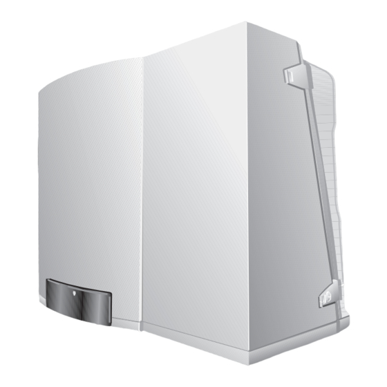
AS EQUIPMENT VENTING SYTEM REQUIRED installation. Product description 14 15 72150200-1.1TD Fig. 1 Logamax plus GB142-24/30 (left) and GB142-45/60 (right) Drawer with control unit Latches of which two have locks Universal Burner Automat (UBA3) [10] Sighting glass Control unit BC10... - Page 6 [13] Air intake for the fan ECO mode means that the temperature inside the hot water tank is 140 °F (60 °C), with a hysteresis (ΔT) of 18 °F (10 °C) instead of 9 °F (5 °C) Logamax plus GB142-24/30/45/60 – 6720820104 (2017/05)
-
Page 7: Dimensions And Connections
4" (100 mm) to the right, 4" (100 mm) at the top and 6" (150 mm) to the left. One Ø 1.0" (Ø 25.4 mm) inside x 1" NPT threaded compression fitting is delivered enclosed with boiler packaging Logamax plus GB142-24/30/45/60 – 6720820104 (2017/05) - Page 8 4" (100 mm) to the right, 4" (100 mm) at the top and 6" (150 mm) to the left. One Ø 1.0'' (Ø 25.4 mm) inside x 1'' NPT threaded compression fitting is delivered enclosed with boiler packaging Logamax plus GB142-24/30/45/60 – 6720820104 (2017/05)
-
Page 9: Packaging And Transportation
▶ Remove the casing by lifting it upwards and then pulling it forwards ( fig. 7, [3]); do not hold the casing by the latches. 72150200-7.1TD Fig. 7 Removing the casing The user’s instructions (in a special format) is located in the boiler drawer Logamax plus GB142-24/30/45/60 – 6720820104 (2017/05) -
Page 10: Making The Gas Connection
90°-Elbow Tee (flow thru Gate valve Gas cocks ▶ Thoroughly flush all pipes and radiators. Use of a Buderus approved in inches branch) boiler cleaner is recommended. Equivalent length in feet ▶ Refer to the installation template for the pipe connection ¾... - Page 11 Drain valve Flue gas [10] Pump manifold shut-off valve Air intake [11] DHW supply 1" FPT Optional DHW tank Primary pump Shut-off valve PT gauge (pressure and temperature gauge) Zone valve Logamax plus GB142-24/30/45/60 – 6720820104 (2017/05)
- Page 12 • Contractor to furnish and install LWCO and Manual Reset High Limit devices as required by local codes. • Do not install any type of value or check valve in between boiler and LWCO or Manual Reset High Limit. Logamax plus GB142-24/30/45/60 – 6720820104 (2017/05)
-
Page 13: Combustion Air And Ventilation Openings
3 inches (75 mm). • Where directly communicating with the outdoors, each opening shall have a minimum free area of 1 square inch per 4,000 Btu/hr of total input rating of all equipment in the enclosure. Logamax plus GB142-24/30/45/60 – 6720820104 (2017/05) -
Page 14: Installation Of The Exhaust And Air Intake System
The boiler can also be operated with separate air intake and exhaust horizontal venting system. The concentric vent/air intake body can be piping ( fig. 18 and fig. 19). ordered by Buderus Hydronic Systems, part no. BRYKGAVTO601CV. Other optional vent kits are: 383-500-397 Plastic Vent Kit 72150200-20.1TD... - Page 15 At least 1 ft (305 mm) above grade and snow line Exhaust terminal must be at least 3 ft (915 mm) above forced air inlet within 10 ft (3050 mm) Forced air inlet Gravity air Inlet Logamax plus GB142-24/30/45/60 – 6720820104 (2017/05)
- Page 16 ▶ A minimum clearance of 4 feet horizontally from and Intake 3" (80 mm) in no case above and below, unless a 4-foot horizontal distance is maintained, from electric gauges, gas gauges, regulators and relief equipment. Logamax plus GB142-24/30/45/60 – 6720820104 (2017/05)
- Page 17 10"- 0" min. (250 mm - 0 mm min.) 24" min. (610 mm min.) 12" (300 mm) over maximum snow level or 24" (600 mm) Intake 3" (80 mm) whichever is greater 3" × 1.5" (80 × 38.1 mm) Intake Logamax plus GB142-24/30/45/60 – 6720820104 (2017/05)
-
Page 18: Conversion To Propane
GB142-60 = 60 ft (18.29 m) - 12 ft (3.64 m) = 48 feet (14.65 m). NOTICE: The minimum covering wall thickness is 1" (25 mm). The maximum covering wall thickness is 16" (406 mm). Logamax plus GB142-24/30/45/60 – 6720820104 (2017/05) - Page 19 This is the terminal where you connect the outdoor temperature sensor. Only necessary for outdoor weather responsive operation. WA terminal For connection of a potential free thermostat or relay panel end switch. Connection for an external DHW tank sensor. Logamax plus GB142-24/30/45/60 – 6720820104 (2017/05)
- Page 20 Safety-temperature sensor Return sensor Ionization 120 VAC 230 VAC 230 VAC 10 VAC 120 VAC 10 VAC 120 VAC 24 VAC 0 VAC 24 VRAC 24 VRAC 120 VAC 72150200-31.1TD Fig. 32 Electric circuit diagram Logamax plus GB142-24/30/45/60 – 6720820104 (2017/05)
-
Page 21: Start-Up Procedure
Turn off all the electric power to the appliance if service is to be perf r r ormed. Set the thermostat or other operating control to lowest setting. Close main gas shut off valve. 708.375A - 2172B 72150200-32.1TD Fig. 33 Logamax plus GB142-24/30/45/60 – 6720820104 (2017/05) -
Page 22: Testing For Gas Leaks
( table 5). condensate bypass pipe. ▶ Convert the burner fitting to another gas type if required ( chapter 6.8 “Conversion to Propane”, page 18). Logamax plus GB142-24/30/45/60 – 6720820104 (2017/05) -
Page 23: Inlet Gas Pressure
Fig. 37 Opening the control panel ▶ Press and hold the “Chimney Sweep” d and “Service” buttons (for approx. five seconds) until the display shows “Lxx” (e. g. L80). Logamax plus GB142-24/30/45/60 – 6720820104 (2017/05) -
Page 24: Carrying Out A Leak Test In Operating Conditions
▶ Cover damageable parts before leak testing. ▶ Do not spray the leak testing agent onto cables, plugs or electrical connection lines. Do not allow it to drip onto them either. 72150200-39.1TD Fig. 41 Measuring the ionization current Logamax plus GB142-24/30/45/60 – 6720820104 (2017/05) -
Page 25: Testing The Ignition Safety Shut Off Device
▶ Check if the boiler starts-up. LED “Burner Operation” ▶ Press the “Chimney Sweep” button return to normal operating Service Tool connector conditions. [10] “Service” button [11] “Chimney sweep” d button [12] “Reset” c button Logamax plus GB142-24/30/45/60 – 6720820104 (2017/05) -
Page 26: Switching The Heating System On And Off
Current boiler water temperature (in °F) Remedy any blocking faults that remain active for a [p/2/1| > P15 Current system pressure (in psi) long time using the service section in this manual. Table 7 Possible status displays Logamax plus GB142-24/30/45/60 – 6720820104 (2017/05) -
Page 27: Carrying Out Additional Tasks
▶ Set the heating capacity by pressing the “Chimney Sweep” button (higher values) or the “Reset” button (lower values). temperature. ▶ Press the “Service” button to confirm the setting. ▶ Press the “Chimney Sweep” button to exit manual mode. Logamax plus GB142-24/30/45/60 – 6720820104 (2017/05) -
Page 28: Setting The Dhw Temperature Value
In summer mode the heating system is switched off (LED emergency off). You must immediately close the main shut-off valve or gas shut-off valve and disconnect the power from the heating system. ▶ Close the main shut-off valve. Logamax plus GB142-24/30/45/60 – 6720820104 (2017/05) -
Page 29: Inspection
Measuring the ionization current Fastening nut See section 8.12“Measuring the ionization current” page 24. Earth cable 11.5 Measuring the inlet gas pressure Hot surface ignitor Ionization electrode See section 8.7“Inlet gas pressure”, page 23. Logamax plus GB142-24/30/45/60 – 6720820104 (2017/05) - Page 30 ▶ Pull the internal condensate bypass pipe from the condensate trap Fig. 47 Cleaning the burner cover, gas/air distributor plate, orifice ( fig 50, [2]). plate and burner Gas burner fitting Gas/air distributor plate Orifice plate Burner Logamax plus GB142-24/30/45/60 – 6720820104 (2017/05)
-
Page 31: Checking And Adjusting The Gas/Air-Ratio
DHW demand and CH request for more then one hour. The boiler then switches to CH mode. The operating code flashing in the display after the service button is pressed is A01/ 818. To enable the DHW, restart the boiler. Logamax plus GB142-24/30/45/60 – 6720820104 (2017/05) -
Page 32: Error Messages
229 Hot-surface ignitor on for too long. Grid voltage 261 The grid power was interrupted after an error. UBA fault. External switching contact External switching contact, e. g. temperature safety switch for floor heating, has taken place. Table 12 Logamax plus GB142-24/30/45/60 – 6720820104 (2017/05) -
Page 33: Technical Specifications
(kg) 110 (50) 110 (50) 143 (65) 158 (72) Table 13 Technical specifications The performance information shown is based on 'European performance standards'. If the heating capacity is limited to max. 80 % (L80). Logamax plus GB142-24/30/45/60 – 6720820104 (2017/05) -
Page 34: Reports
12. Make the necessary settings on the thermostat 13. Carry out function testing 14. Fitting the casing 15. Inform the owner; hand over the technical documents Confirm proper start-up Company stamp/signature/date Table 16 Logamax plus GB142-24/30/45/60 – 6720820104 (2017/05) -
Page 35: Inspection Report
2. Check and adjust the gas/air ratio _____________ inch W.C. _____________ inch W.C. content with full load _____________ % _____________ % content with partial load _____________ % _____________ % Confirm proper maintenance Company stamp/ Company stamp/ signature signature Table 18 Logamax plus GB142-24/30/45/60 – 6720820104 (2017/05) -
Page 36: Spare Parts
Seal mounting plate (5 pc) 7098850 number in the exploded view drawing on the next 2 pages for the Air inlet pipe; 24/30 kW 7099024 illustration. Spare parts may be ordered from Buderus. Air inlet pipe; 45/60 kW 7099923 Pos. Description Product No. - Page 37 Seal pump (10 pc) 15022s Coupling nut pump 15020 Conversion set pump 73149 Flue gas adaptor drain set, incl. pos. 44 8718600686 Flue gas silencer 24/30/45 kW 7099056 Table 19 not shown in exploded views Logamax plus GB142-24/30/45/60 – 6720820104 (2017/05)
- Page 38 Spare parts Exploded view Logamax plus GB142-24/30 72150200-49.1TD Fig. 52 Logamax plus GB142-24/30/45/60 – 6720820104 (2017/05)
- Page 39 Spare parts Exploded view Logamax plus GB142-45/60 72150200-50.1TD Fig. 53 Logamax plus GB142-24/30/45/60 – 6720820104 (2017/05)