Advertisement
Quick Links
Download this manual
See also:
Configuration Manual
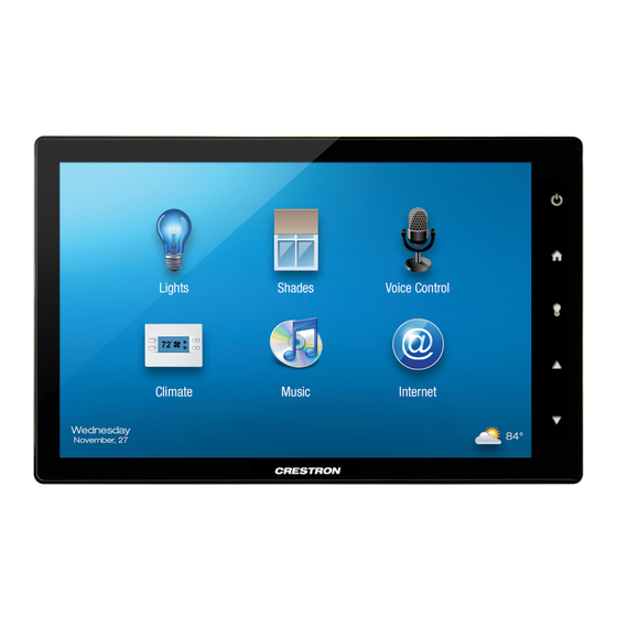
TSW-1052
10.1" Touch Screen
1
Install the Touch Screen
The Crestron
®
TSW-1052 touch screen installs into a standard 2-gang or 3-gang U.S electrical box or a
2-gang European electrical box. It can also be attached directly to drywall and other surfaces over the
front of a 2 3/8" (60 mm) high by 3 3/8" (86 mm) wide cutout. When installed, it protrudes just 1/2"
(13 mm) from the mounting surface and magnetically adheres to its included mounting bracket.
It is supplied with screws for installation.
To mount the TSW-1052 into an electrical box, use the following procedure:
1. Use four of the eight included screws (four #06-32 x 3/4" or four 3 x 16 mm) to attach the mounting
bracket (2034503) to the electrical box, as shown in the following illustrations.
For U.S.-style installations, use the #06-32 x 3/4" screws (2033247).
For European-style installations, use the 3 x 16 mm screws (2013788).
NOTE: For U.S.-style installations, use a #2 Phillips screwdriver. For European-style installations,
use a #1 Phillips screwdriver or equivalent.
Mount the TSW-1052 into a U.S. Electrical Box
Mounting Bracket
(2034503)
1
For regulatory compliance information, refer to Doc. 7577.
QUICKSTART DOC. 7576B (2040593, Sheet 1 of 2)
U.S. Electrical Box
Screws (4) #06-32 x 3/4"
(2033247)
TSW-1052
www.crestron.com
07.14
Specifications subject to
change without notice.
Mount the TSW-1052 into a European Electrical Box
European Electrical Box
Mounting Bracket
(2034503)
TSW-1052
2. Power and data connection to the TSW-1052 is provided by a single Ethernet cable connected to
the LAN port at the rear of the unit. A Crestron PoE power supply or PoE-capable network switch is
recommended. Apply power after the Ethernet cable is connected.
Hardware Connections for the TSW-1052
Reset Button
LAN PoE:
10BASE-T/100BASE-TX
Ethernet to LAN
3. Carefully position the touch screen over the mounting bracket and gently place it in position.
The magnets on the rear of the touch screen hold it in place on the mounting bracket.
888.273.7876
201.767.3400
Screws (4) 3 x 16 mm
(2013788)
Advertisement

Related Manuals for Crestron TSW-1052


Summary of Contents for Crestron TSW-1052
- Page 1 2. Power and data connection to the TSW-1052 is provided by a single Ethernet cable connected to the LAN port at the rear of the unit. A Crestron PoE power supply or PoE-capable network switch is recommended. Apply power after the Ethernet cable is connected.
- Page 2 “Install the Touch Screen” for details. There is a single method of communication: TCP/IP communication. NOTE: The TSW-1052 can take up to 120 seconds to boot to a display after initial power up. Ethernet Communication When power is applied for the first time, the screen Power shown in the illustration to the right appears.
- Page 3 TSW-1052 10.1” Touch Screen Dimensions Pinout Reference TSW-1052 Overall Dimensions (Top View) The only connector on the TSW-1052 is the LAN PoE port. 3.36 in LAN PoE (86 mm) Pin 1 Pin 8 Speakers Yellow Green DESCRIPTION TSW-1052 Overall Dimensions (Front and Side Views)
-
Page 4: Specifications
Video may be used in this document to refer to either the entities claiming the marks and names or their products. Crestron disclaims any proprietary interest in the marks and names of others. Crestron is not responsible for errors in typography or photography.