Advertisement
Quick Links
Download this manual
See also:
Configuration Manual
DO
GUIDE
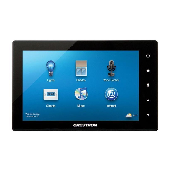
TSW-752
7" Touch Screen
DO
Install the Touch Screen
The Crestron
®
TSW-752 touch screen installs easily over a standard 2-gang or 3-gang U.S.
electrical box or over a 2-gang European electrical box. It can also be attached directly to
drywall and other surfaces over the front of a 2 3/8" (60 mm) high by 3 3/8" (86 mm) wide cutout.
When installed, the touch screen protrudes just 1/2" (13 mm) from the mounting surface and is
magnetically adhered to its mounting bracket, eliminating any visible screws for an ultra clean
appearance.
NOTE:
For proper positioning of the touch screen, the electrical box or cutout must be
positioned approximately 1/4" (6 mm) to the right of the touch screen's center and 1/10" (3 mm)
above its center.
To mount the TSW-752 into an electrical box, use the following procedure:
1. Use four of the eight included screws (four 06-32 x 3/4" or four 3 x 16 mm screws) to attach
the mounting bracket to the electrical box, as shown in the following illustrations.
NOTE:
For U.S.-style installations, use a #2 Phillips screwdriver. For European-style
installations, use a #1 Phillips screwdriver or equivalent.
For U.S.-style installations, use the 06-32 x 3/4" screws.
DO
Check the Box
QTY PRODUCT
1
Cable Mount Ferrite Bead
1
Mounting Bracket
4
Screws, 06-32 x 3/4", Undercut Head, Phillips
4
Screws, 3 x 16 mm, Flat Head, Phillips
For European-style installations, use the 3 x 16 mm screws.
2. Make connections to the TSW-752 using Crestron power supplies for Crestron equipment.
Apply power after all connections have been made.
NOTE:
The included cable mount ferrite bead, FBTH-2, should be placed on the LAN
cable in the electrical box.
3. Carefully hold the touch screen over the mounting bracket and gently place it in position.
The magnets on the rear of the touch screen hold it in place on the mounting bracket.
DO
Connect the Device
Connect the TSW-752 to the LAN as shown in the following illustration.
COLOR
PART NUM.
2033216
4516761
2033247
2013788
Advertisement

Related Manuals for Crestron TSW-752


Summary of Contents for Crestron TSW-752
- Page 1 For U.S.-style installations, use a #2 Phillips screwdriver. For European-style installations, use a #1 Phillips screwdriver or equivalent. For U.S.-style installations, use the 06-32 x 3/4” screws. 2. Make connections to the TSW-752 using Crestron power supplies for Crestron equipment. Apply power after all connections have been made. NOTE: The included cable mount ferrite bead, FBTH-2, should be placed on the LAN cable in the electrical box.
- Page 2 However, there is no guarantee that interference will not and trade names may be used in this document to refer to either the entities claiming the marks and names or their products. Crestron disclaims any proprietary interest in the marks and names occur in a particular installation.