Advertisement
Quick Links
Download this manual
See also:
Owner's Manual
INSTALLATION GUIDE
INSTALLATION GUIDE
INSTALLATION GUIDE
TECH SUPPORT
TECH SUPPORT
TECH SUPPORT
Western Canada 1 800 279-0636
Western Canada 1 800 279-0636
Western Canada 1 800 279-0636
United States: 1 866 698-5872
United States: 1 866 698-5872
United States: 1 866 698-5872
Eastern Canada. Bilingual Support: 1 800 268-0683
Eastern Canada. Bilingual Support: 1 800 268-0683
Eastern Canada. Bilingual Support: 1 800 268-0683
E-Mail Tech Support: support@ultrastarters.com
E-Mail Tech Support: support@ultrastarters.com
E-Mail Tech Support: support@ultrastarters.com
Check Our Web Site: www.ultrastarters.com
Check Our Web Site: www.ultrastarters.com
Check Our Web Site: www.ultrastarters.com
Advanced Remote Vehicle
Advanced Remote Vehicle
Advanced Remote Vehicle
Starting System
Starting System
Starting System
AUTOMATIC AND MANUAL
TRANSMISSION MODELS
WWW.ULTRASTARTERS.COM
See website for a full size printable version of this manual.
WARNING!! NEVER INSTALL A
AUTOMATIC REMOTE STARTER
IN A MANUAL TRANSMISSION VEHICLE
SERIOUS INJURY OR DEATH CAN RESULT
This device complies with Part 15 of the FCC rules. Operation is subject to the
following conditions:
(1) This device may not cause harmful interference, and
(2) This device must accept any interference received, including interference
that may cause undesired operation.
CAUTION: Changes or modifications not expressly approved by the part
responsible for compliance void the user's authority to operate this devise.
1600
1600
1600
1600
1600
1600
1600M
1600M
1600M
1600M
1600M
1600M
FCC/ID Notice
Advertisement

Related Manuals for Ultra Start 1600


Summary of Contents for Ultra Start 1600
- Page 1 1600 1600 1600 1600 1600 1600 INSTALLATION GUIDE INSTALLATION GUIDE INSTALLATION GUIDE 1600M 1600M 1600M 1600M 1600M 1600M Advanced Remote Vehicle Advanced Remote Vehicle Advanced Remote Vehicle Starting System Starting System Starting System AUTOMATIC AND MANUAL TRANSMISSION MODELS WWW.ULTRASTARTERS.COM See website for a full size printable version of this manual.
- Page 2 Installation Guide Table Of Contents 1600 Wiring Diagram Page 3 Pre-Installation Page 4 What’s Included Pre Installation Check Installation Procedures Wire Connectors Page 5 6 Pin Connector 14 Pin Connector 4 Pin Red Connector Jumper Settings Installation Page 6-7 Basic Installation - Quick start...
-
Page 3: Wiring Diagram
Installation Guide WIRING DIAGRAM Starter Output Yellow (+) 30amp Output Accessory Output Green (+) 30amp Output Main Power (+) 30amp Input Main Power (+) 30amp Input White Selectable Output (+) 30amp Output Blue Ignition 1 Output (+) 30amp Output Yellow Re-Arm/Output 1* (-)500ma Output Orange... - Page 4 Installation Guide Product Description And Installation Components - Control module - 6 button Remote transmitter(s) - RF Antenna (With Program Switch And LED’s) - 14 pin harness - 6 pin main harness with dual 30amp power inputs - 4 pin keyless entry harness - Hood pin safety switch - Install and Owners manual Feature List...
- Page 5 Installation Guide Wiring Connectors 6 Pin Power Connector Yellow Starter 30amp output 12volts during crank only. Green Accessory 30amp output 12volts in accessory off during start. 12 power 30amp input Constant12volt power 12 power 30amp input Constant 12volt power. Blue Ignition 1 30amp output 12volts in ignition and start positions.
- Page 6 Installation Guide Quick Start Installation Step 1 - The Following Wires Must Be Connected! 6 Pin Power Connector Yellow Starter Output Connect To The Vehicles Starter Wire. Green Heater Output Connect To The Vehicles Accessory Wire. 12 power Input Connect to Constant 12 Volt Power Source 12 power Input Connect to Constant 12 Volt Power Source Blue...
- Page 7 Installation Guide Programming Introduction Programming Overview Program mode allows you to adjust the settings and options of your system. The system’s default settings do not require any program changes in most cases. However, this system does incorporate a highly advanced programming system that includes 5 menus with numerous options and settings that can be easily adjusted for custom installations.
- Page 8 Installation Guide Menu 1 - User Settings Setting 1- Ignition Auto Lock 1 Ignition Lock Enabled 1 Light Flash Lock when ignition is turned On unlock when off 2 Ignition Lock Only 2 Light Flashes Lock when ignition is On, no unlock when Off. *3 Ignition Lock Disabled 3 Light Flashes Doors do not Lock or Unlock with Ignition Press the Program Switch 1 time to select setting 1 (This will be confirmed by 1 LED flash and one park light flash)
- Page 9 Installation Guide Menu 3 - Starter Settings Setting 1- Special Door Lock/ Unlock Operations 1 Type 1 1 Flash Unlock before start, lock after start and and shutdown 2 Type 2 2 Flashes Lock pulse after the remote starter shuts off 3* Normal Operation 3 Flashes No additional re-lock pulses...
- Page 10 Installation Guide Menu 4 - Tach Settings Setting 1- Method 1- Auto Tach Learn 1) Plug in the module, the park lights will flash and the horn will honk two times.* *If the lights do not flash check connections. Ign must be off when plugged-in. 2) Turn the Ignition Key to the ON position.
- Page 11 Installation Guide Menu 5 - Auxiliary Output Settings New Auxiliary Output Menu. The auxiliary output menu allows the installer to choose the output on a desired wire from the main unit. This option will allow for such things as custom remote features, additional remote starter accessories and button configurations.
- Page 12 Installation Guide Auxiliary Output Explanation Of Settings Auxiliary Outputs Ground On Start (Low Current) This output will supply a 500ma ground output at the same time the starter motor engages. The output will stay on until the starter motor disengages. This output can be used for Low Crank (Bulb Test) activation on the GM Passlock system, GM Daytime Running Lights, Second Starter Relays and Negative starter wire like what is found on the 2001/2002 Dodge Caravans.
- Page 13 Manual Transmission Vehicles Installation Guide Manual Transmission Remote Starters. Never Install A Automatic Transmission Remote Starter Into A Manual Transmission Vehicle!!! If installing on a convertible vehicle,(NOT RECOMMENDED) Install a radar sensor to protect the proximity of the gear shift lever. The radar should be connected so that if the field is disturbed the radar sensor module will trigger the door or hood input which will cancel the Reservation Mode.
- Page 14 Installation Guide Other Features Cold Start Mode 1.Press and release the # button, then within two seconds press and hold the button for six seconds. After six second the park lights will turn “On” and the start interval can be selected. 2.
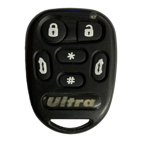
- Page 15 Installation Guide Transmitter Operations Transmitter Programming Step 1 - Within three seconds turn the Key ON-OFF-ON-OFF-ON - Leaving Key ON Step 2 - Press and hold the Program Switch - Parking Lights will come ON **if park- lights do not come on at this point, turn key off for 5 seconds, the repeat step 1. Step 3 - Continue to hold the Program Switch until park lights go out.
-
Page 16: Door Lock Diagrams
Installation Guide Door Lock Diagrams Negative Type Door Locks Vehicle Lock To Control Lock/Unlock Relay or Switch Actuators lock Green Blue Positive Type Door Locks Vehicle Lock Lock/Unlock Fused +12V lock Switch Green Blue To Control Relay or Actuator 5 Wire / Reverse Polarity Type Door Locks Fused +12V Green Blue...