Table of Contents
Advertisement
Quick Links
Advertisement
Table of Contents

Related Manuals for Draytek Vigor 2130 Series


Summary of Contents for Draytek Vigor 2130 Series
- Page 2 Vigor2130 Series High Speed Gigabit Router User’s Guide Version: 1.5 Firmware Version: V1.5.0.1 Date: 12/01/2010 Vigor2130 Series User’s Guide...
-
Page 3: Copyright Information
Copyright Information Copyright Copyright 2011 All rights reserved. This publication contains information that is Declarations protected by copyright. No part may be reproduced, transmitted, transcribed, stored in a retrieval system, or translated into any language without written permission from the copyright holders. -
Page 4: European Community Declarations
European Community Declarations Manufacturer: DrayTek Corp. Address: No. 26, Fu Shing Road, HuKou County, HsinChu Industrial Park, Hsin-Chu, Taiwan 303 Product: Vigor2130 Series Router DrayTek Corp. declares that Vigor2130 Series of routers are in compliance with the following essential requirements and other relevant provisions of R&TTE Directive 1999/5/EEC. The product conforms to the requirements of Electro-Magnetic Compatibility (EMC) Directive 2004/108/EC by complying with the requirements set forth in EN55022/Class B and EN55024/Class B. -
Page 5: Table Of Contents
Preface .......................1 1.1 Features ..........................1 1.2 Web Configuration Buttons Explanation ................. 1 1.3 LED Indicators and Connectors ....................2 1.3.1 For Vigor2130 ........................2 1.3.2 For Vigor2130n ......................... 4 1.3.3 For Vigor2130Vn....................... 6 1.4 Hardware Installation ......................8 Stand Installation ........................9 1.5 Printer Installation ......................... - Page 6 3.3 NAT ............................58 3.3.1 Hardware NAT ........................ 59 3.3.2 Open Ports........................59 3.3.3 DMZ Host........................61 3.4 Bandwidth Management ....................... 62 3.4.1 Session Limit ........................62 3.4.2 Bandwidth Limit ......................63 3.4.3 Port Rate Control ......................65 3.4.4 QoS Control List ......................65 3.4.5 Ports Priority ........................
-
Page 7: Admin Mode Operation
3.11.2 TR-069 ........................138 3.11.3 User Password ......................139 3.11.4 Configuration Backup ....................140 3.11.5 Syslog / Mail Alert ....................... 142 3.11.6 Time and Date ......................144 3.11.7 Management....................... 145 3.11.8 Reboot System ......................146 3.11.9 Firmware Upgrade ...................... 146 Admin Mode Operation..................147 4.1 WAN ............................ - Page 8 4.8 VPN and Remote Access....................216 4.8.1 Remote Access Control ....................216 4.8.2 PPTP Remote Dial-in....................217 4.8.3 IPSec Remote Dial-in ....................220 4.8.4 Remote Dial-in Status....................221 4.8.5 LAN to LAN........................223 4.9 Wireless LAN ........................227 4.9.1 Basic Concepts......................227 4.9.2 General Setup.......................
- Page 9 4.15.4 Traffic Overview......................295 4.15.5 Detailed Statistics ....................... 296 4.15.6 MAC Address Table....................298 4.15.7 DHCP Table........................ 299 4.15.8 Data Flow Monitor....................... 300 4.15.9 Sessions Table ......................301 4.15.10 Ports State ........................ 302 Applications ....................303 5.1 How to Configure Multi-VLAN in Vigor Router ..............303 5.2 LAN to LAN IPSec VPN between Vigor2130 and Vigor2820 using Main mode ....
-
Page 11: Preface
The Vigor2130 series are the routers with high speed in data transmission through WAN port and LAN ports. With hardware NAT acceleration, the rate of Vigor2130 series can be ideal for multi-media application. With the development of NGN (Next Generation Network), you may recently hear the news about FTTx deployment in your local area or even have already subscribed the unbundling last mile service (e.g. -
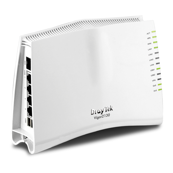
Page 12: Led Indicators And Connectors
Note: For the other buttons shown on the web pages, please refer to Chapter 4 for detailed explanation. Before you use the Vigor router, please get acquainted with the LED indicators and connectors first. Status Explanation Blinking The router is powered on and running (Activity) normally. - Page 13 Interface Description Factory Reset Restore the default settings. Usage: Turn on the router (ACT LED is blinking). Press the hole and keep for more than 5 seconds. When you see the ACT LED begins to blink rapidly than usual, release the button. Then the router will restart with the factory default configuration.
-
Page 14: For Vigor2130N
Status Explanation Blinking The router is powered on and running (Activity) normally. The router is powered off. Hardware NAT is enabled. Hardware NAT is disabled. On (Orange) The port is connected with 100Mbps. On (Green) The port is connected with 1000Mbps. The port is disconnected. - Page 15 Interface Description Factory Reset Restore the default settings. Usage: Turn on the router (ACT LED is blinking). Press the hole and keep for more than 5 seconds. When you see the ACT LED begins to blink rapidly than usual, release the button. Then the router will restart with the factory default configuration.
-
Page 16: For Vigor2130Vn
Status Explanation Blinking The router is powered on and running (Activity) normally. The router is powered off. Hardware NAT is enabled. Hardware NAT is disabled. On (Orange) The port is connected with 100Mbps. On (Green) The port is connected with 1000Mbps. The port is disconnected. - Page 17 Interface Description Phone2/Phone1 Connector of analog phone for VoIP communication Factory Reset Restore the default settings. Usage: Turn on the router (ACT LED is blinking). Press the hole and keep for more than 5 seconds. When you see the ACT LED begins to blink rapidly than usual, release the button.
-
Page 18: Hardware Installation
Before starting to configure the router, you have to connect your devices correctly. Connect Line port to land line jack with a RJ-11 cable (Vn model). Connect this device to a modem with an Ethernet cable. Connect one port of 4-port switch to your computer with a RJ-45 cable. This device allows you to connect 4 PCs directly. -
Page 19: Stand Installation
The Vigor2130 must be placed erectly. Therefore you have to install a stand onto the router to make it standing firmly. Please follow the figures listed below to finish the installation. Vigor2130 Series User’s Guide... -
Page 20: Printer Installation
You can install a printer onto the router for sharing printing. All the PCs connected this router can print documents via the router. The example provided here is made based on Windows XP/2000. For Windows 98/SE/Vista, please visit www.draytek.com. Before using it, please follow the steps below to configure settings for connected computers (or wireless clients). - Page 21 Click Local printer attached to this computer and click Next. In this dialog, choose Create a new port Type of port and use the drop down list to select Standard TCP/IP Port. Click Next. Vigor2130 Series User’s Guide...
- Page 22 In the following dialog, type 192.168.1.1 (router’s LAN IP) in the field of Printer Name or IP Address and type IP_192.168.1.1 as the port name. Then, click Next. Click Standard and choose Generic Network Card. Then, in the following dialog, click Finish. Vigor2130 Series User’s Guide...
- Page 23 Now, your system will ask you to choose right name of the printer that you installed onto the router. Such step can make correct driver loaded onto your PC. When you finish the selection, click Next. 10. For the final stage, you need to go back to Control Panel-> Printers and edit the property of the new printer you have added.
- Page 24 The printer can be used for printing now. Most of the printers with different manufacturers are compatible with vigor router. Note 1: Some printers with the fax/scanning or other additional functions are not supported. If you do not know whether your printer is supported or not, please visit www.draytek.com to find out the printer list.
-
Page 25: Configuring Basic Settings
For using the router properly, it is necessary for you to change the password of web configuration for security and adjust primary basic settings. This chapter explains how to setup a password for an administrator/user and how to adjust basic/advanced settings for accessing Internet successfully. For user mode operation, do not type any word on the window and click Login for the simple web pages for configuration. -
Page 26: Changing Password
No matter user mode operation or admin mode operation, please change the password for the original security of the router. Open a web browser on your PC and type http://192.168.1.1. A pop-up window will open to ask for username and password. Please type “admin/admin”... - Page 27 Go to System Maintenance page and choose System Password/User Password. Type New Password in New Password and Confirm New Password fields. Then click OK to continue. Now, the password has been changed. Next time, use the new password to access the Web Configurator for this router.
-
Page 28: Quick Start Wizard
Notice: Quick Start Wizard for user mode operation is the same as for admin mode operation. If your router can be under an environment with high speed NAT, the configuration provide here can help you to deploy and use the router quickly. The first screen of Quick Start Wizard is welcome page, please click Next. -
Page 29: Setting Up The Time Zone
On the next page as shown below, please select the Time Zone for the router installed and specify the NTP server(s). Then click Next for next step. On the next page as shown below, please select the appropriate connection type according to the information from your ISP. - Page 30 You will receive a fixed public IP address or a public subnet, namely multiple public IP addresses from your DSL or Cable ISP service providers. In most cases, a Cable service provider will offer a fixed public IP, while a DSL service provider will offer a public subnet. If you have a public subnet, you could assign an IP address or many IP address to the WAN interface.
- Page 31 It is not necessary for you to type any IP address manually. Simply choose this type and the system will obtain the IP address automatically from DHCP server. Enable The router will detect the MAC address automatically. Or, check the box to enable MAC address cloning. Clone MAC Address It is available when the box of Enable is checked.
- Page 32 If your ISP provides you the PPPoE connection, please select PPPoE for this router. The following page will be shown: User Name Assign a specific valid user name provided by the ISP. Password Assign a valid password provided by the ISP. Redial Policy If you want to connect to Internet all the time, you can choose Always On.
- Page 33 if you click PPTP/L2TP as the protocol, please manually enter the Username/Password provided by your ISP and all the required information. User Name Assign a specific valid user name provided by the ISP. Password Assign a valid password provided by the ISP. Server Address Specify the IP address of the PPTP server.
-
Page 34: Setting Up The Wireless Connection
After finishing the settings here, please click Next. Now, you have to set up the wireless connection. For the user of Vigor2130, please skip this step. Enable Wireless LAN Check the box to enable the wireless function. SSID Broadcast Choose Show to make the SSID being seen by wireless clients. Choose Hide to prevent from wireless sniffing and make it harder for unauthorized clients or STAs to join your wireless LAN. - Page 35 WEP encryption bit size and have the same key. Four keys can be entered here, but only one key can be selected at a time. The keys can be entered in ASCII or Hexadecimal. Choose the key you wish to use by using the Default Key drop down list.
- Page 36 If you choose WPA-PSK as the security configuration, you have to specify WPA mode, algorithm and pre-shared key. Type The WPA encrypts each frame transmitted from the radio using the key, which either PSK (Pre-Shared Key) entered manually in this field below or automatically negotiated via 802.1x authentication.
- Page 37 Remote Authentication Dial-In User Service (RADIUS) is a security authentication client/server protocol that supports authentication, authorization and accounting, which is widely used by Internet service providers. It is the most common method of authenticating and authorizing dial-up and tunneled network users. The built-in RADIUS client feature enables the router to assist the remote dial-in user or a wireless station and the RADIUS server in performing mutual authentication.
- Page 38 WPS (Wi-Fi Protected Setup) provides easy procedure to make network connection between wireless station and wireless access point (vigor router) with the encryption of WPA and WPA2. If you choose WPS as the security configuration, you can press Start WPS PIN and Start WPS PBC to complete the wireless connection.
-
Page 39: Saving The Wizard Configuration
Now you can see the following screen. It indicates that the setup is complete. Different types of connection modes will have different summary. Click Finish and then restart the router. The online status shows the system status, WAN status, and other status related to this router within one page. -
Page 40: Saving Configuration
RX Packets Displays the total received packets at the LAN interface. TX Bytes Displays the total transmitted bytes at the LAN interface. RX Bytes Displays the total received packets at the LAN interface. IPv6 Address Displays the IPv6 address of the LAN interface. WAN Status Displays the IP address of the WAN interface. -
Page 41: User Mode Operation
This chapter will guide users to execute simple configuration through user mode operation. Open a web browser on your PC and type http://192.168.1.1. The window will ask for typing username and password. Do not type any word (both username and password are Null for user operation) on the window and click Login on the window. - Page 42 As the router plays a role to manage and further protect its LAN, it interconnects groups of host PCs. Each of them has a private IP address assigned by the built-in DHCP server of the Vigor router. The router itself will also use the default private IP address: 192.168.1.1 to communicate with the local hosts.
-
Page 43: Internet Access
Below shows the menu items for WAN. This page allows you to set WAN configuration with different modes. Use the Connection Type drop down list to choose one of the WAN modes. The corresponding page will be displayed. Enable Check the box to enable the WAN IP configuration. Connection Type Use the Connection Type drop down list to choose one of the WAN modes. - Page 44 Below shows the configuration page for each connection type: For static IP mode, you usually receive a fixed public IP address or a public subnet, namely multiple public IP addresses from your DSL or Cable ISP service providers. In most cases, a Cable service provider will offer a fixed public IP, while a DSL service provider will offer a public subnet.
- Page 45 IP Address Type the IP address. Subnet Mask Type the subnet mask. Gateway IP Address Type the gateway IP address. Primary DNS Server Type in the primary IP address for the router if you want to use Static IP mode. Secondary DNS Server Type in secondary IP address for using in the future if necessary.
- Page 46 DHCP allows a user to obtain an IP address automatically from a DHCP server on the Internet. If you choose DHCP mode, the DHCP server of your ISP will assign a dynamic IP address for your router automatically. It is not necessary for you to assign any setting, Router Name Type in a name for the router.
- Page 47 To choose PPPoE as the accessing protocol of the internet, please select PPPoE from the Internet Access menu. The following web page will be shown. Username Type in the username provided by ISP in this field. Password Type in the password provided by ISP in this field. Redial Policy If you want to connect to Internet all the time, you can choose Always On.
- Page 48 Enable/Disable Click Enable for activating this function. If you click Disable, this function will be closed and all the settings that you adjusted in this page will be invalid. Mode Such function allows you to verify whether network connection is alive or not through ARP Detect or Ping Detect. Choose ARP Detect or Ping Detect for the system to execute for WAN detection.
- Page 49 Server Address Type in the IP address for PPTP /L2TP server. WAN IP Network Settings You can choose Static IP or DHCP as WAN IP network setting. IP Address Type the IP address if you choose Static IP as the WAN IP network setting.
- Page 50 If your router connects to a 3G modem and you want to access Internet via 3G modem, choose 3G as connection type and type the required information in this web page. SIM PIN code Type PIN code of the SIM card that will be used to access Internet.
-
Page 51: Multi-Vlan
Vigor2130 series offers multi-VLAN function to make the data transmission with security. Data transmitting through the DSL port for connecting to Internet can be tagged with an ID number specified here for ensuring the security. In addition, each LAN port also can be tagged with an ID number in local network to reach the goal of protection. - Page 52 from ISP for transmitting data from PC directly without NAT. The range of ID number you can type is from 2 – 4096. Each ID setting must be unique and different with WAN VLAN ID. VoIP WAN is the interface specified for the usage of VoIP. The settings will be changed based on the connection type selected.
-
Page 53: Ports
Domain Name Type the domain name obtained from the ISP. When PPPoE is selected as connection type, you need to configure the following settings: Username Type the name obtained from the ISP. Password Type the password obtained from the ISP. Confirm Password Type the password again for confirmation. - Page 54 Flow Control If flow control is enabled by checking Configured box, both parties can send PAUSE frame to the transmitting device(s) if the receiving port is too busy to handle. If not, there will be no flow control in the port. It drops the packet if too much to handle.
-
Page 55: Backup
Refresh Click this button to refresh the information for WAN port. After finishing all the settings here, please click OK to activate them. This page is used to setup 3G backup function. If you enable 3G backup, make sure your WAN connection type is not in 3G mode. -
Page 56: Lan
Local Area Network (LAN) is a group of subnets regulated and ruled by router. The design of network structure is related to what type of public IP addresses coming from your ISP. The most generic function of Vigor router is NAT. It creates a private subnet of your own. As mentioned previously, the router will talk to other public hosts on the Internet by using public IP address and talking to local hosts by using its private IP address. - Page 57 Vigor router will exchange routing information with neighboring routers using the RIP to accomplish IP routing. This allows users to change the information of the router such as IP address and the routers will automatically inform for each other. You can group local hosts by physical ports and create up to 4 virtual LANs. To manage the communication between different groups, please set up rules in Virtual LAN (VLAN) function and the rate of each.
-
Page 58: General Setup
Below shows the LAN menu: This page provides you the general settings for LAN. Click LAN to open the LAN settings page and choose General Setup. Type in private IP address for connecting to a local private IP Address network (Default: 192.168.1.1). Subnet Mask Type in an address code that determines the size of the network. - Page 59 DHCP server for your network so it automatically dispatch related IP settings to any local user configured as a DHCP client. It is highly recommended that you leave the router enabled as a DHCP server if you do not have a DHCP server for your network.
-
Page 60: Ports
Ports page is used to change the setting for LAN ports. You can set or reset the following items. All of them are described in detail below. Port It displays current network interface. It displays current connection status. Green light means the Link WAN connection is successful. - Page 61 Discard - It determines whether the MAC drops frames after an excessive collision has occurred. If yes, a frame is dropped after excessive collision. This is IEEE Standard 802.3 half-duplex flow control operation. Restart - It determines whether the MAC retransmits frames after an excessive collision has occurred.
-
Page 62: Mac Address Table
This page allows you to set timeouts for entries in dynamic MAC Table and configure the static MAC table here. Disable Automatic Aging Stop the MAC table aging timer, the learned MAC address will not age out automatically. The default setting is enabled. Check the box to disable this function if required. -
Page 63: Vlan
To add a new static MAC entry, click Add new static entry. A new entry will be shown as follows. Choose VLAN ID and type a new MAC address. Next, specify port member for this table. Finally, click OK to save the changes. Virtual LAN function provides you a very convenient way to manage hosts by grouping them based on the physical port. -
Page 64: Monitor Port
To add or remove a VLAN, please refer to the following example. VLAN 1 is consisted of hosts linked to P1 ~ P4. After checking the box to enable VLAN function, you will check the table according to the needs as shown below. To remove VLAN, click the Delete button for the one you want to remove and click OK to save the results. -
Page 65: Static Route
Go to LAN and choose Static Route to open setting page. Set to Factory Default Click this link to return to the factory default settings. View Routing Table Click this link to view the routing table. Index The number (1 to 10) under Index displays current static router. - Page 66 Click the LAN - Static Route and click Add. Check the Enable box. Please add a static route as shown below, which regulates all packets destined to 192.168.10.0 will be forwarded to 192.168.1.2. Click OK. Return to Static Route page. Click Add again to add another static route as show below, which regulates all packets destined to 211.100.88.0 will be forwarded to 192.168.1.3.
-
Page 67: Bind Ip To Mac
This function is used to bind the IP and MAC address in LAN to have a strengthening control in network. When this function is enabled, all the assigned IP and MAC address binding together cannot be changed. If you modified the binding IP or MAC address, it might cause you not access into the Internet. -
Page 68: Nat
newly ARP table information. IP Bind List It displays a list for the IP bind to MAC information. It allows you to add the one you choose from the ARP table or the IP/MAC address typed in Add and Edit to the table of IP Bind List. -
Page 69: Hardware Nat
Hardware-base Acceleration Engine, also named Protocol Processing Engine API is the function that Draytek provides to extremely speed up the NAT performance. While the hardware acceleration mechanism is activated, most of the bandwidth usage will be concentrated on the specific sessions which increase transmission speed to get ultimately accelerated. - Page 70 Protocol Specify the transport layer protocol. It could be TCP, UDP and TCP+UDP. WAN IP Specify one WAN IP address to be used by such profile. The default setting is ALL, which mean such profile can be applied for all the WAN IP addresses. Start Port Specify the starting port number of the service offered by the local host.
-
Page 71: Dmz Host
Vigor router provides a facility DMZ Host that maps ALL unsolicited data on any protocol to a single host in the LAN. Regular web surfing and other such Internet activities from other clients will continue to work without inappropriate interruption. DMZ Host allows a defined internal user to be totally exposed to the Internet, which usually helps some special applications such as Netmeeting or Internet Games etc. -
Page 72: Bandwidth Management
Below shows the menu items for Bandwidth Management. A PC with private IP address can access to the Internet via NAT router. The router will generate the records of NAT sessions for such connection. The P2P (Peer to Peer) applications (e.g., BitTorrent) always need many sessions for procession and also they will occupy over resources which might result in important accesses impacted. -
Page 73: Bandwidth Limit
Start IP Defines the start LAN IP address for limit session. End IP Defines the end LAN IP address for limit session. Sessions Limit Defines the available session number for each host in the specific range of IP addresses. If you do not set the session number in this field, the system will use the default session limit for the specific limitation you set for each index. - Page 74 Smart Bandwidth Limit Click this radio button to configure the default limitation for bandwidth. When session number exceeds – type the value here as a threshold to apply the smart bandwidth limit. TX limit - Define the default speed of the upstream for each computer in LAN.
-
Page 75: Port Rate Control
A policer can limit the bandwidth of received frames. It is located in front of the ingress queue. And a shaper can limit the bandwidth of transmitted frames. It is located after the ingress queues. This page allows you to configure the switch port rate limit for Policers and Shapers. Port Represent LAN or WAN interface. - Page 76 Scheduling: Based on classification of service level to assign packets to queues and associated service types The basic QoS implementation in Vigor routers is to classify and schedule packets based on the service type information in the IP header. For instance, to ensure the connection with the headquarter, a teleworker may enforce an index of QoS Control to reserve bandwidth for HTTPS connection while using lots of application at the same time.
- Page 77 QCE Type Display the type of that QCE (QoS Control Entries). Type Value Display the value specified for the QCE. Traffic Class Display the class of the data transmission for the QCE. QoS Control List allows users to set up to five groups of QCL. Each QCL group can contain 12 QCE settings.
- Page 78 Ethernet Type Value Either 8~63 ASCII characters, such as 012345678(or 64 Hexadecimal digits leading by 0x, such as "0x321253abcde..."). If you choose VLAN ID as QCE Type, you have to type the ID number for it and specify traffic class from Low, Normal, Medium and High. If you choose TCP/UDP Port as QCE Type, you have to type the port number for it and specify traffic class from Low, Normal, Medium and High.
- Page 79 If you choose DSCP as QCE Type, you have to type value for it and specify traffic class from Low, Normal, Medium and High. If you choose ToS as QCE Type, you have to specify priority class from Low, Normal, Medium and High.
-
Page 80: Ports Priority
Click to modify the settings of an existing QCE on this page. Click to move a QCE up and down. To delete a QCE in the list, simply click of that one. It will be removed immediately. This page allows you to configure QoS settings for each port. The classification is controlled by a QCL (Quality Control List) that is assigned to each port. -
Page 81: Qos Statistics
Queuing Mode Use the drop down list to choose suitable mode. Queue Weighted Use the drop down list to choose 1, 2, 4, or 8 as the queue weighted number. Click OK to save the settings. This page displays statistics for QoS setting. Click WAN/LAN link to check detailed information for each interface. - Page 82 Rx Packets Display the counting number of the packet received. Rx Octets Display the total received bytes. Rx Unicast Display the counting number of the received unicast packet. Rx Broadcast Display the counting number of the received broadcast packet. Rx Pause Display the counting number of the received pause packet.
- Page 83 packets received. Rx Low Display the low queue counter of the packet received. Rx Normal Display the normal queue counter of the packet received. Rx Medium Display the medium queue counter of the packet received. Rx High Display the high queue counter of the packet received. Rx Drops Display the number of frames dropped due to the lack of receiving buffer.
-
Page 84: Applications
Tx Medium Display the medium queue counter of the packet received. Tx High Display the high queue counter of the packet received. Tx Drops Display the number of frames dropped due to excessive collision, late collision, or frame aging. Tx lat/Exc.Coll. Display the number of Frames late collision or excessive collision Error, which switch transmitted. -
Page 85: Schedule
Enable Dynamic DNS Check this box to enable the current account. Service Provider Select the service provider for the DDNS account. Domain name Type in one domain name that you applied previously. Use the drop down list to choose the desired domain. Username Type in the login name that you set for applying domain. - Page 86 Enable Check to enable the schedule. Start Date Specify the starting date of the schedule. Start Time Specify the starting time of the schedule. Action Specify which action should be applied during the period of the schedule. WAN UP/DOWN – WAN connection will be activated / inactivated based on the time schedule configured here.
-
Page 87: Igmp
IGMP snooping means multicast traffic will be forwarded to ports that have members of that group. If you disable IGMP snooping, the system will make multicast traffic treated in the same manner as broadcast traffic. Enable IGMP Proxy Check the box to enable this function. The IGMP proxy can act as a multicast proxy for hosts on LAN sides. -
Page 88: Upnp Configuration
V1~3 Reports Receive Display the number of Received V1 – V3 Reports. V2 Leave Receive Display the number of Received V2 Leave. Groups IGMP groups. Maximum number of Display current group for each VLAN can be set is 128. Port Members Display the LAN ports in this group. - Page 89 The UPnP facility on the router enables UPnP aware applications such as MSN Messenger to discover what are behind a NAT router. The application will also learn the external IP address and configure port mappings on the router. Subsequently, such a facility forwards packets from the external ports of the router to the internal ports used by the application.
-
Page 90: Wake On Lan
The UPnP function dynamically adds port mappings on behalf of some UPnP-aware applications. When the applications terminate abnormally, these mappings may not be removed. A PC client on LAN can be woken up by the router it connects. When a user wants to wake up a specified PC through the router, he/she must type correct MAC address of the specified PC on this web page of Wake On LAN of this router. -
Page 91: Wireless Lan
This function is used for “n” models. Over recent years, the market for wireless communications has enjoyed tremendous growth. Wireless technology now reaches or is capable of reaching virtually every location on the surface of the earth. Hundreds of millions of people exchange information every day via wireless communication products. -
Page 92: General Setup
WEP (Wired Equivalent Privacy) is a legacy method to encrypt each frame transmitted via radio using either a 64-bit or 128-bit key. Usually access point will preset a set of four keys and it will communicate with each station using only one out of the four keys. WPA (Wi-Fi Protected Access), the most dominating security mechanism in industry, is separated into two categories: WPA-personal or called WPA Pre-Share Key (WPA/PSK), and WPA-Enterprise or called WPA/802.1x. - Page 93 Check the box to enable the wireless function. Enable Wireless LAN Show/Hide Choose Show to make the SSID being seen by wireless clients. Choose Hide to prevent from wireless sniffing and make it harder for unauthorized clients or STAs to join your wireless LAN.
- Page 94 point. The greater the value is, the higher intensity of the signal will be. Enable Green AP Such function is used to reduce the power consumption (Green AP) for the access point. When there is no station connected, the power consumption of access point will be reduced. Enable IGMP Snooping Check it to enable IGMP snooping for WLAN client.
- Page 95 Default Key All wireless devices must support the same WEP encryption bit size and have the same key. Key1-Key4 Four keys can be entered here, but only one key can be selected at a time. The format of WEP Key is restricted to 5 ASCII characters or 10 hexadecimal values in 64-bit encryption level, or restricted to 13 ASCII characters or 26 hexadecimal values in 128-bit encryption level.
- Page 96 WPA Algorithm Select TKIP, AES or auto as the algorithm for WPA. WPA Pre-Shared Key Either 8~63 ASCII characters, such as 012345678..(or 64 Hexadecimal digits leading by 0x, such as "0x321253abcde..."). WPA-RADIUS The built-in RADIUS client feature enables the router to assist the remote dial-in user or a wireless station and the RADIUS server in performing mutual authentication.
- Page 97 Configure via Push Button Click Start PBC to invoke Push-Button style WPS setup procedure. The router will wait for WPS requests from wireless clients about two minutes. The WPS LED on the router will blink fast when WPS is in progress. It will return to normal condition after two minutes.
-
Page 98: Access Control
of a station with network card installed, press Start PBC button of network card. If you want to use PIN code, you have to know the PIN code specified in wireless client. Then provide the PIN code of the wireless client you wish to connect to the vigor router. For additional security of wireless access, the Access Control facility allows you to restrict the network access right by controlling the wireless LAN MAC address of client. -
Page 99: Station List
here are allowed to do wireless connection. Deny List – all the MAC address of wireless clients listed here will be blocked. Add a new MAC address into the list. Add a New Entry Delete Delete the selected MAC address in the list. This button will appear only an entry of MAC Address has been typed. -
Page 100: Access Point Discovery
Vigor router can scan all regulatory channels and find working APs in the neighborhood. Based on the scanning result, users will know which channel is clean for usage. Note: During the scanning process (about 5 seconds), no client is allowed to connect to Vigor. - Page 101 Scan It is used to discover all the connected AP. The results will be shown on the box above this button. WMM Capable To apply WMM parameters for wireless data transmission, please click the Enable radio button. APSD Capable The default setting is Disable. It controls how long the client waits for each data Aifsn transmission.
-
Page 102: Wds
the web page. If you want to modify the parameters, please refer to the Wi-Fi WMM standard specification AckPolicy “Uncheck” (default value) the box means the AP router will answer the response request while transmitting WMM packets through wireless connection. It can assure that the peer must receive the WMM packets. - Page 103 The application for the WDS-Repeater mode is depicted as below: In Bridge mode, the router will connect to up to four Vigor2130 which use the same mode, and all wired Ethernet clients of every Vigor2130 will be connected together. You can use this mode to connect a network to other networks which is physically isolated.
-
Page 104: Usb Application
the second one. Security There are four types for security, Disabled, WEP, TKIP and Key or Peer Mac Address field valid or not. Choose one of the types for the router. Please disable the unused link to get better performance. Type 8 ~ 63 ASCII characters or 64 hexadecimal digits leading by “0x”. -
Page 105: Usb General Settings
At present, the Vigor router can support USB storage disk with versions of FAT16 and NTFS only. Therefore, before connecting the USB storage disk into the Vigor router, please make sure the memory format for the USB storage disk is FAT16 or NTFS. It is recommended for you to use NTFS for viewing the filename completely (FAT16 cannot support long filename). -
Page 106: Disk Status
Volume Select the proper volume for the connected USB disk. Home Folder It determines the range for the client to access into. The user can enter a directory name in this field. Then, after clicking OK, the router will create the specific/new folder in the USB diskette. -
Page 107: Disk Shares
This page can define the folder which will be shared while Samba File Sharing is enabled. To add a new entry for disk sharing, please click Add a New Entry to open the following page. Share Name Type a name to be known by other computers in local network. -
Page 108: Bit Torrent Download
that want to connect to the attached USB disk. All Users Read-only - everyone has read-only access to the share disk. All Users Read-write - everyone has read-write access to the share disk. Specific Users – Only specific user(s) can access into the share disk. - Page 109 BT Function Enable – Click it to enable BT download function after powering your computer. Disable – Click it to disable BT download function after powering your computer Start – Start the BT download process. Stop – Stop the BT download process. Type the port number to listen for incoming peer Listening Port connection.
-
Page 110: Itunes Server
Remote Management Enable – Click it to enable remote control for BT torrent download. Disable – Click it to disable remote management function. Save the settings. Uninstall Cancel the module installation settings and exit the dialog. For the detailed information of BT Torrent application, please refer to Chapter 5. iTunes server is one of the most popular programs for managing media content on a computer. -
Page 111: Dlna Server
service. “/” is the symbol for the top folder of USB storage. Rescan Interval The USB storage disk will be scanned by iTunes Server again based on the time interval set here. The unit is second. Save the settings. Uninstall Cancel the module installation settings and exit the dialog. -
Page 112: Voip
needed. Path After storing the files in the USB storage device, please specify a path for the files to be accessed for DLNA service. “/” is the symbol for the top folder of USB storage. Save the settings. Uninstall Cancel the module installation settings and exit the dialog. Note: This function is used for “V”... - Page 113 The major benefit of this mode is that you don’t have to memorize your friend’s IP address, which might change very frequently if it’s dynamic. Instead of that, you will only have to using dial plan or directly dial your friend’s account name if you are with the same SIP Registrar.
-
Page 114: Dialplan
This page allows you to set phone book and digit map for the VoIP function. Click the Phone Book, Digit Map, Call Barring and Regional links on the page to access into next pages for dialplan settings. In this section, you can set your VoIP contacts in the “phonebook”. It can help you to make calls quickly and easily by using “speed-dial”... - Page 115 Enable Click this to enable this entry. Phone Number The speed-dial number of this index. This can be any number you choose, using digits 0-9 and * . The Caller-ID that you want to be displayed on your Display Name friend’s screen.
- Page 116 Enable Check this box to invoke this setting. Prefix Number The phone number set here is used to add, strip, or replace the OP number. None - No action. Mode Add - When you choose this mode, the OP number will be added with the prefix number for calling out through the specific VoIP interface.
- Page 117 Call barring is used to block phone calls coming from the one that is not welcomed. Click any index number to display the dial plan setup page. Enable Click this to enable this entry. Call Direction Determine the direction for the phone call, IN – incoming call, OUT-outgoing call, IN &...
- Page 118 Specific URI/URL or This field will be changed based on the type you selected for Specific Number barring Type. Interface All means all the phone calls will be blocked with such mechanism. Additionally, you can set advanced settings for call barring such as Block Anonymous, Block Unknown Domain or Block IP Address.
- Page 119 This page allows you to process incoming or outgoing phone calls by regional. Default values (common used in most areas) will be shown on this web page. You can change the number based on the region that the router is placed. Enable Regional Check this box to enable this function.
-
Page 120: Sip Accounts
end. Hide caller ID [Deact] Dial the number typed in this field to release this function. Dial the number typed in this field to make all the incoming Call Waiting [Act] calls waiting for your answer. Call Waiting [Deact] Dial the number typed in this field to release this function. In this section, you set up your own SIP settings. - Page 121 Status Show the status for the corresponding SIP account. R means such account is registered on SIP server successfully. – means the account is failed to register on SIP server. Click any index number to access into the following page. Profile Name Assign a name for this profile for identifying.
- Page 122 Domain/Realm Set the domain name or IP address of the SIP Registrar server. Proxy Set domain name or IP address of SIP proxy server. By the time you can type :port number after the domain name to specify that port as the destination of data transmission (e.g., nat.draytel.org:5065) Act as Outbound Proxy Check this box to make the proxy acting as outbound proxy.
-
Page 123: Phone Settings
This page allows user to set phone settings for Phone 1 and Phone 2 respectively. However, it changes slightly according to different model you have. Port – there are two phone ports provided here for you to Phone List configure. Phone1/Phone2 allows you to set general settings for PSTN phones. - Page 124 Also, you can specify each field for your necessity. It is recommended for you to use the default settings for VoIP communication. Caller ID Type – Display IP type of the caller. Symmetric RTP – Check this box to invoke the function. To make the data transmission going through on both ends of local router and remote router not misleading due to IP lost (for example, sending data from the public IP of...
- Page 125 Click the number link for Phone port, you can access into the following page for configuring Phone settings. Check the box to enable it. Type in the SIP URL in the Hotline field for dialing automatically when you pick up the phone set.
- Page 126 the phone set. Call Waiting Check this box to invoke this function. A notice sound will appear to tell the user new phone call is waiting for your response. Click hook flash to pick up the waiting phone call. Call Transfer Check this box to invoke this function.
- Page 127 Default SIP Account You can set SIP accounts (up to six groups) on SIP Account page. Use the drop down list to choose one of the profile names for the accounts as the default one for this phone setting. Play dial tone only when account registered - Check this box to invoke the function.
-
Page 128: Status
OutBand - Choose this one then the Vigor will capture the keypad number you pressed and transform it to digital form then send to the other side; the receiver will generate the tone according to the digital form it receive. This function is very useful when the network traffic congestion occurs and it still can remain the accuracy of DTMF tone. - Page 129 ACTIVE-Indicates that the VoIP connection is launched. Codec Indicates the voice codec employed by present channel. PeerID The present in-call or out-call peer ID (the format may be IP or Domain). Elapse The format is represented as hours:minutes:seconds. Tx Pkts Total number of transmitted voice packets during this connection session.
-
Page 130: Ipv6
This page defines the IPv6 connection types for WAN interface. Possible types contain Link-Local only, Static IPv6, DHCPv6 and TSPC. Each type requires different parameter settings. Link-Local address is used for communicating with neighbouring nodes on the same link. It is defined by the address prefix fe80::/10. - Page 131 This type allows you to setup static IPv6 address for WAN. IPv6 Address Type your IPv6 static IP here. Prefix Length Type your IPv6 address prefix length here. Gateway IPv6 Server Type your IPv6 gateway address here. Primary DNS Server Type your IPv6 primary DNS Server address here.
- Page 132 DHCPv6 client mode would use IA_PA option of DHCPv6 protocol to obtain IPv6 prefix from server. SLA ID It is used by an individual organization to create its own local addressing hierarchy and to identify subnets. Tunnel setup protocol client (TSPC) is an application which could help you to connect to IPv6 network easily.
- Page 133 Username Type the name obtained from the broker. “vigor2130” is a default username applied from http://go6.net/4105/register.asp. It is suggested for you to apply another username and password. Password Type the password assigned with the user name. Type the password again to make the confirmation. Confirm Password Tunnel Broker Type the address for the tunnel broker IP, FQDN or an...
-
Page 134: Ipv6 Lan Setup
This page defines the IPv6 connection types for LAN interface. Possible types contain DHCPv6 and RADVD. Each type requires different parameter settings. IPv6 Address Type static IPv6 address for LAN. IPv6 Link_local Address It is used for communicating with neighbouring nodes on the same link. -
Page 135: Ipv6 Firewall Setup
Advertisement Lifetime -- The lifetime associated with the default router in units of seconds. It's used to control the lifetime of the prefix. The maximum value corresponds to 18.2 hours. A lifetime of 0 indicates that the router is not a default router and should not appear on the default router list. - Page 136 Click Add New Rule to configure a new rule for IPv6 Firewall. Note: You can set up to 20 sets of IPv6 rules. Name Type a name for the rule. Protocol Specify a protocol for this rule. Source IP Type Determine the IP type as the source.
- Page 137 Destination IP Type the IP address here if you choose Single as Destination IP Type. Type the subnet mask here if you choose Subnet as Destination Subnet Destination IP Type. Source Start Port Type a value as the source start port. Such value will be available only TCP/UDP is selected as the protocol.
-
Page 138: Ipv6 Routing
In the following dialog, please configure the page with the following values. Connect PC to http://www.ipv6.org/ with IPv6 IP address again. A message will appear from web page: Welcome to the IPv6 Information Page! You are using IPv4 from 114.37.132.219 This page displays the routing table for the protocol of IPv6. -
Page 139: Ipv6 Neighbour
Display the largest size (in bytes) of a packet. Advmss Display the largest size (in bytes) of an unfragmented piece of a routing advertisement. Display the number of network segments on which the Hoplimit packet is allowed to travel before discarded. Auto-refresh Check this box to enable an automatic refresh of the page at regular intervals. -
Page 140: Ipv6 Tspc Status
IPv6 TSPC status web page could help you to diagnose the connection status of TSPC. TSPC log contains some debug information from program. If TSPC has not configured properly, the router will display the following page when the user tries to connect through TSPC connection. When TSPC configuration has been done, the router will start to connect. - Page 141 Connection Status It will bring out different pages to represent IPv6 disconnection, connecting and connected. Tunnel Information Display interface name (used to send TSPC prefix), tunnel mode, local endpoint addresses, remote endpoint address, TSPC Prfix, TSPC Prefixlen (prefix length), tunnel broker and so on.
- Page 142 When your PC obtains the IPv6 address, please connect to http://www.ipv6.org. If your PC access Internet via IPv6 connection, your IPv6 address will be shown on the web page immediately. Refer to the following figure. Vigor2130 Series User’s Guide...
-
Page 143: Ipv6 Management
This page allows you to manage the settings for IPv6 access control including settings of HTTP, HTTPs, SSH, FTP and TELNET by using IPv6 protocol. Check the box and type the port number respectively to enable the remote management of services. Enable Enable the checkbox to allow system administrators to login HTTP/HTTPS/SSH/ICMP... -
Page 144: User
This page allows you to set user’s setting that allowed to use PPTP, FTP, IPSEC/L2TP connection. Click Add a New User to open the following page. Enable Check this box to enable such user profile. Username Type a name for this user. Full Name Type full name for this user. - Page 145 through PPTP. When such user profile needs to have PPTP LAN to LAN connection, the following three items must be adjusted. Enable PPTP LAN to LAN – Check this box to let such user profile supporting PPTP LAN to LAN. Local Network / Mask –Traffic between this subnet and the subnet specified in Remote Network / Mask will travel through the VPN tunnel.
-
Page 146: System Maintenance
For the system setup, there are several items that you have to know the way of configuration: Status, TR-069, User Password, Configuration Backup, Syslog/Mail Alert, Time and Date, Management, Reboot System and Firmware Upgrade. Below shows the menu items for System Maintenance. The System Status provides basic network settings of Vigor router. - Page 147 Memory Usage Display the size of the memory usage and the percentage. LAN------- MAC Address Display the MAC address of the LAN Interface. IP Address Display the IP address of the LAN interface. IP Mask Display the subnet mask address of the LAN interface. IPv6 Address (Global) Display the global IPv6 address of the LAN interface.
-
Page 148: 138
Vigor router with TR-069 is available for matching with VigorACS server. Such page provides VigorACS and CPE settings under TR-069 protocol. All the settings configured here is for CPE to be controlled and managed with VigorACS server. Users need to type URL, username and password for the VigorACS server that such device will be connected. -
Page 149: User Password
Server. Enable/Disable – Allow/Deny the CPE Client to connect with Auto Configuration Server. Port – Sometimes, port conflict might be occurred. To solve such problem, you might change port number for CPE. Periodic Inform Settings Disable – The system will not send inform message to ACS server. -
Page 150: Configuration Backup
Follow the steps below to backup your configuration. Go to System Maintenance >> Configuration Backup. The following windows will be popped-up, as shown below. Type a key arbitrarily for encrypting the file. Keep the key in mind. You will need it whenever you want to restore such file. - Page 151 Click Save button, the configuration will download automatically to your computer as a file named config.cfg. The above example is using Windows platform for demonstrating examples. The Mac or Linux platform will appear different windows, but the backup function is still available. Note: Backup for Certification must be done independently.
-
Page 152: Syslog / Mail Alert
SysLog function is provided for users to monitor router. There is no bother to directly get into the Web Configurator of the router or borrow debug equipments. Enable (Syslog Access…) Check “Enable” to activate function of syslog. Router Name Assign a name of this device. The IP address of the Syslog server. - Page 153 Enable E-mail Alert Check the box of User Login to send alert message to the e-mail box while the router detecting the item(s) you specify here. Click OK to save these settings. For viewing the Syslog, please do the following: Just set your monitor PC’s IP address in the field of Server IP Address Install the Router Tools in the Utility within provided CD.
-
Page 154: Time And Date
It allows you to specify where the time of the router should be inquired from. Current System Time Display current time in the box. Click Inquire Time to get the current time. Time Zone Select the time zone where the router is located. Automatically Update Specify a time interval for the router to update current time. -
Page 155: Management
This page allows you to manage the settings for access control, access list, port setup, and SMP setup. For example, as to management access control, the port number is used to send/receive SIP message for building a session. The default value is 5060 and this must match with the peer Registrar when making VoIP calls. -
Page 156: Reboot System
The Web Configurator may be used to restart your router for using current configuration. Click Reboot System from System Maintenance to open the following page. Click OK. The router will take 5 seconds to reboot the system. Note: When the system pops up Reboot System web page after you configure web settings, please click OK to reboot your router for ensuring normal operation and preventing unexpected errors of the router in the future. -
Page 157: Admin Mode Operation
This chapter will guide users to execute advanced (full) configuration through admin mode operation. Open a web browser on your PC and type http://192.168.1.1. The window will ask for typing username and password. Please type “admin/admin” on Username/Password for administration operation. Now, the Main Screen will appear. - Page 158 From 10.0.0.0 to 10.255.255.255 From 172.16.0.0 to 172.31.255.255 From 192.168.0.0 to 192.168.255.255 As the router plays a role to manage and further protect its LAN, it interconnects groups of host PCs. Each of them has a private IP address assigned by the built-in DHCP server of the Vigor router.
-
Page 159: Internet Access
Modem will be listed on DrayTek web site. Please visit www.draytek.com for more detailed information. Below shows the menu items for WAN. This page allows you to set WAN configuration with different modes. Use the Connection Type drop down list to choose one of the WAN modes. The corresponding page will be displayed. - Page 160 Below shows the configuration page for each connection type: For static IP mode, you usually receive a fixed public IP address or a public subnet, namely multiple public IP addresses from your DSL or Cable ISP service providers. In most cases, a Cable service provider will offer a fixed public IP, while a DSL service provider will offer a public subnet.
- Page 161 IP Address Type the IP address. Subnet Mask Type the subnet mask. Gateway IP Address Type the gateway IP address. Primary DNS Server You must specify a DNS server IP address here because your ISP should provide you with usually more than one DNS Server. If your ISP does not provide it, the router will automatically apply default DNS Server IP address: 198.95.1.1 to this field.
- Page 162 DHCP allows a user to obtain an IP address automatically from a DHCP server on the Internet. If you choose DHCP mode, the DHCP server of your ISP will assign a dynamic IP address for your router automatically. It is not necessary for you to assign any setting, Router Name Type in a name for the router.
- Page 163 To choose PPPoE as the accessing protocol of the internet, please select PPPoE from the Internet Access menu. The following web page will be shown. Username Type in the username provided by ISP in this field. Password Type in the password provided by ISP in this field. Redial Policy If you want to connect to Internet all the time, you can choose Always On.
- Page 164 Detect or Ping Detect for the system to execute for WAN detection. Ping IP If you choose Ping Detect as detection mode, you have to type IP address in this field for pinging. Enable/Disable Click Enable for activating this function. If you click Disable, this function will be closed and all the settings that you adjusted in this page will be invalid.
- Page 165 WAN IP Network Settings You can choose Static IP or DHCP as WAN IP network setting. IP Address Type the IP address if you choose Static IP as the WAN IP network setting. Subnet Mask Type the subnet mask if you chose Static IP as the WAN IP. Primary DNS Server You must specify a DNS server IP address here because your ISP should provide you with usually more than one DNS Server.
- Page 166 If your router connects to a 3G modem and you want to access Internet via 3G modem, choose 3G as connection type and type the required information in this web page. SIM PIN code Type PIN code of the SIM card that will be used to access Internet.
-
Page 167: Multi-Vlan
Vigor2130 series offers multi-VLAN function to make the data transmission with security. Data transmitting through the DSL port for connecting to Internet can be tagged with an ID number specified here for ensuring the security. In addition, each LAN port also can be tagged with an ID number in local network to reach the goal of protection. - Page 168 from ISP for transmitting data from PC directly without NAT. The range of ID number you can type is from 2 – 4096. Each ID setting must be unique and different with WAN VLAN ID. VoIP WAN is the interface specified for the usage of VoIP. The settings will be changed based on the connection type selected.
-
Page 169: Ports
Domain Name Type the domain name obtained from the ISP. When PPPoE is selected as connection type, you need to configure the following settings: Username Type the name obtained from the ISP. Password Type the password obtained from the ISP. Confirm Password Type the password again for confirmation. - Page 170 Flow Control If flow control is enabled by checking Configured box, both parties can send PAUSE frame to the transmitting device(s) if the receiving port is too busy to handle. If not, there will be no flow control in the port. It drops the packet if too much to handle.
-
Page 171: Backup
Refresh Click this button to refresh the information for WAN port. After finishing all the settings here, please click OK to activate them. This page is used to setup 3G backup function. If you enable 3G backup, make sure your WAN connection type is not in 3G mode. -
Page 172: Lan
Local Area Network (LAN) is a group of subnets regulated and ruled by router. The design of network structure is related to what type of public IP addresses coming from your ISP. The most generic function of Vigor router is NAT. It creates a private subnet of your own. As mentioned previously, the router will talk to other public hosts on the Internet by using public IP address and talking to local hosts by using its private IP address. - Page 173 Vigor router will exchange routing information with neighboring routers using the RIP to accomplish IP routing. This allows users to change the information of the router such as IP address and the routers will automatically inform for each other. When you have several subnets in your LAN, sometimes a more effective and quicker way for connection is the Static routes function rather than other method.
-
Page 174: General Setup
This page provides you the general settings for LAN. Click LAN to open the LAN settings page and choose General Setup. IP Address Type in private IP address for connecting to a local private network (Default: 192.168.1.1). Subnet Mask Type in an address code that determines the size of the network. -
Page 175: Ports
220.135.240.2 or greater, but smaller than 220.135.240.254. IP Pool Counts Enter the number of IP addresses in the pool. The maximum is 10. For example, if you type 3 and the 2nd IP address of your router is 220.135.240.1, the range of IP address by the DHCP server will be from 220.135.240.2 to 220.135.240.11. - Page 176 Port It displays current network interface. Link It displays current connection status. Green light means the WAN connection is successful. It displays current speed that the router uses. Speed Current Speed Configured You can use the drop down list to choose the required speed for the router.
-
Page 177: Mac Address Table
Disabled: All power savings mechanisms disabled. ActiPHY: Link down power savings enabled. PerfectReach: Link up power savings enabled. Enabled: Both link up and link down power savings enabled. Refresh Click this button to refresh the information for WAN port. After finishing all the settings here, please click OK to activate them. This page allows you to set timeouts for entries in dynamic MAC Table and configure the static MAC table here. -
Page 178: Vlan
mechanism, only support static MAC address setting. Secure - Disable this port MAC address dynamic learning mechanism and copy the dynamic learning packets to CPU. Specify static MAC address with VLAN ID to apply aging Static MAC Table Config.. configuration. Delete - Click the button to remove the VLAN setting. -
Page 179: Monitor Port
To add or remove a VLAN, please refer to the following example. VLAN 1 is consisted of hosts linked to P1 ~ P4. After checking the box to enable VLAN function, you will check the table according to the needs as shown below. To remove VLAN, click the Delete button for the one you want to remove and click OK to save the results. -
Page 180: Static Route
Go to LAN to open setting page and choose Static Route. Set to Factory Default Click this link to return to the factory default settings. View Routing Table Click this link to view the routing table. Index The number (1 to 10) under Index displays current static router. - Page 181 Click the LAN - Static Route and click Add. Check the Enable box. Please add a static route as shown below, which regulates all packets destined to 192.168.10.0 will be forwarded to 192.168.1.2. Click OK. Return to Static Route page. Click Add again to add another static route as show below, which regulates all packets destined to 211.100.88.0 will be forwarded to 192.168.1.3.
-
Page 182: Bind Ip To Mac
This function is used to bind the IP and MAC address in LAN to have a strengthening control in network. When this function is enabled, all the assigned IP and MAC address binding together cannot be changed. If you modified the binding IP or MAC address, it might cause you not access into the Internet. -
Page 183: Nat
It allows you to add the one you choose from the ARP table or the IP/MAC address typed in Add and Edit to the table of IP Bind List. Edit It allows you to edit and modify the selected IP address and MAC address that you create before. -
Page 184: Hardware Nat
Hardware-base Acceleration Engine, also named Protocol Processing Engine API is the function that Draytek provides to extremely speed up the NAT performance. While the hardware acceleration mechanism is activated, most of the bandwidth usage will be concentrated on the specific sessions which increase transmission speed to get ultimately accelerated. - Page 185 Enable Check this box to enable this function. Name Specify the name for the defined network service. Protocol Specify the transport layer protocol. It could be TCP, UDP and TCP+UDP. WAN IP Specify one WAN IP address to be used by such profile. The default setting is ALL, which mean such profile can be applied for all the WAN IP addresses.
-
Page 186: Dmz Host
As mentioned above, Port Redirection can redirect incoming TCP/UDP or other traffic on particular ports to the specific private IP address/port of host in the LAN. However, other IP protocols, for example Protocols 50 (ESP) and 51 (AH), do not travel on a fixed port. Vigor router provides a facility DMZ Host that maps ALL unsolicited data on any protocol to a single host in the LAN. -
Page 187: Firewall
While the broadband users demand more bandwidth for multimedia, interactive applications, or distance learning, security has been always the most concerned. The firewall of the Vigor router helps to protect your local network against attack from unauthorized outsiders. It also restricts users in the local network from accessing the Internet. -
Page 188: Ports Configuration
to set the rate for data transmission. The rate is 2^n, where n is equal to or less than 15, or "No Limit". The unit of the rate can be either pps (packets per second) or kpps (kilopackets per second). The configuration indicates the permitted packet rate for unicast, multicast, or broadcast traffic across the switch. - Page 189 Counter Counts the number of frames that match this Access Control Entry (ACE). Refresh Click this button to refresh the number of the counter immediately. Clear Click this button to clear the number of the counter on this page. Click OK to save the settings. Configure the rate limiter for the ACL (Access Control List) of the router.
- Page 190 Click OK to save the settings. Vigor2130 Series User’s Guide...
-
Page 191: Access Control List
This page can define which kind of packet can access the router. The packet can be defined with input port, Frame type, Rate, MAC type, VLAN ID, tag and etc.. For IPv4, we can also define the protocol type, source IP and destination IP. Click to add a new specific session limitation onto the list. - Page 192 list will be applied to if matching with the rule defined in this page. Rate Limiter - Select a rate limiter to apply to this port. Available settings include Disabled, and 1 to 10. The default value is Disabled. Click the Rate Limiter link to configure different rates for each ID.
- Page 193 ARP/RARP Choose the ARP/RARP that you want to filter. Request/Reply Choose the request or replay that you want to filter. Sender IP Filter Specify the sender IP filter for this ACE. Choose Any to filter all of the packets. Choose Host to filter the packets from the host with the address typed in Sender IP Address filed.
- Page 194 Target IP Address Type the Target IP Address here. This option is available when you choose Host or Network as Target IP Filter. Target IP Mask Type the Target IP Mask here. This option is available only when you choose Network as Target IP Filter. ARP SMAC Match Specify whether frames/packets can meet the action according to the sender hardware address field (SHA)
- Page 195 0: ARP/RARP frames where the hardware address space is equal to Ethernet (1) must not match this entry. 1: ARP/RARP frames where the hardware address space is equal to Ethernet (1) must match this entry. Any: Any value is allowed. Ethernet Specify whether frames can hit the action according to their ARP/RARP protocol address space (PRO) settings.
- Page 196 Dest IP Filter Specify the destination IP filter for this ACE. Any: No destination IP filter is specified. Host: Destination IP filter is set to Host. Specify the destination IP address in the Dest IP Address field that appears. Network: Destination IP filter is set to Network. Specify the destination IP address and destination IP mask in the DIP Address and Dest IP Mask fields that appear.
- Page 197 Source IP Specify the source IP filter for this ACE. Any: No source IP filter is specified. Host: Source IP filter is set to Host. Specify the source IP address in the Source IP Address field that appears. Network: Source IP filter is set to Network. Specify the source IP address and source IP mask in the Source IP Address and Source IP Mask fields that appear.
- Page 198 Specific: If you want to filter a specific UDP source filter with this ACE, you can enter a specific UDP source value. A field for entering a UDP source value appears. Range: If you want to filter a specific UDP source range filter with this ACE, you can enter a specific UDP source range value.
- Page 199 Choose IPv4 as the Frame Type. You will see IP Parameters on the bottom of the page. If you choose TCP as IP Protocol Filter, you will get the page as the following: Source IP Specify the source IP filter for this ACE. Any: No source IP filter is specified.
- Page 200 Source Port Filter Specify the TCP port source filter for this ACE. Any: No TCP source filter is specified. Specific: If you want to filter a specific TCP source filter with this ACE, you can enter a specific TCP source value. A field for entering a TCP source value appears.
- Page 201 TCP SYN Specify the TCP "Synchronize sequence numbers" (SYN) value for this ACE. 0: TCP frames where the SYN field is set must not be able to match this entry. 1: TCP frames where the SYN field is set must be able to match this entry.
- Page 202 1: TCP frames where the URG field is set must be able to match this entry. Any: Any value is allowed. Choose IPv4 as the Frame Type. You will see IP Parameters on the bottom of the page. If you choose Other as IP Protocol Filter, you will get the page as the following: IP Protocol Value When "Other"...
-
Page 203: Traffic Control
destination IP address and destination IP mask fields that appear. Dest IP Address Type the Dest IP Address here. This option is available when you choose Host or Network as destination IP filter. Dest IP Mask Type the Dest IP Mask here. This option is available only when you choose Network as destination IP filter. -
Page 204: Csm
Source Specify the interface for the starting point. Destination Specify the interface for the ending point. Protocol Specify the protocol(s) which this filter rule will apply to. Source Port / Destination Type a fixed port number or a range of port number for such Port rule. - Page 205 Web Content Filter If you do not check any box here, it means Vigor router will not prevent users from accidentally downloading malicious codes conceal in the executable objects from web pages. Filters – Choose any one of the items to be filtered by such router.
-
Page 206: Im/P2P Blocking
Enable IM/P2P Blocking Check this box to enable such function. Only new network connection will be influenced by such rule. Add Entry Click it add a new IM/P2P blocking rule. You are allowed to add many firewall rules for your request. Simply click Add Entry, the following screen will be shown. -
Page 207: Bandwidth Management
Syslog Check this box to record the information on Syslog. Simply check the box(s) that you want to block and click OK to save the settings. Below shows the menu items for Bandwidth Management. A PC with private IP address can access to the Internet via NAT router. The router will generate the records of NAT sessions for such connection. -
Page 208: Bandwidth Limit
in LAN. Limitation List Displays a list of specific limitations that you set on this web page. Defines the start LAN IP address for limit session. Start IP End IP Defines the end LAN IP address for limit session. Sessions Limit Defines the available session number for each host in the specific range of IP addresses. - Page 209 Enable Click this button to activate the function of limit bandwidth. Smart Bandwidth Limit Click this radio button to configure the default limitation for bandwidth. When session number exceeds – type the value here as a threshold to apply the smart bandwidth limit. TX limit - Define the default speed of the upstream for each computer in LAN.
-
Page 210: Port Rate Control
A policer can limit the bandwidth of received frames. It is located in front of the ingress queue. And a shaper can limit the bandwidth of transmitted frames. It is located after the ingress queues. This page allows you to configure the switch port rate limit for Policers and Shapers. Port Represent LAN or WAN interface. - Page 211 Classification: Identifying low-latency or crucial applications and marking them for high-priority service level enforcement throughout the network. Scheduling: Based on classification of service level to assign packets to queues and associated service types The basic QoS implementation in Vigor routers is to classify and schedule packets based on the service type information in the IP header.
- Page 212 QCE Type Display the type of that QCE (QoS Control Entries). Type Value Display the value specified for the QCE. Traffic Class Display the class of the data transmission for the QCE. QoS Control List (QCL) allows users to set up to five groups of QCL. Each QCL group can contain 12 QCE settings.
- Page 213 Ethernet Type Value Either 8~63 ASCII characters, such as 012345678(or 64 Hexadecimal digits leading by 0x, such as "0x321253abcde..."). If you choose VLAN ID as QCE Type, you have to type the ID number for it and specify traffic class from Low, Normal, Medium and High. If you choose TCP/UDP Port as QCE Type, you have to type the port number for it and specify traffic class from Low, Normal, Medium and High.
- Page 214 If you choose ToS as QCE Type, you have to specify priority class from Low, Normal, Medium and High. If you choose Tag Priority as QCE Type, you have to specify priority class from Low, Normal, Medium and High. Click to modify the settings of an existing QCE on this page.
-
Page 215: Ports Priority
To delete a QCE in the list, simply click of that one. It will be removed immediately. This page allows you to configure QoS settings for each port. The classification is controlled by a QCL (Quality Control List) that is assigned to each port. A QCL consists of an ordered list of up to 12 QCEs (Quality Control Entry). -
Page 216: Qos Statistics
Queue Weighted Use the drop down list to choose 1, 2, 4, or 8 as the queue weighted number. Click OK to save the settings. This page displays statistics for QoS setting. Click WAN/LAN link to check detailed information for each interface. Click WAN/LAN link to check detailed information for each interface. - Page 217 Rx Packets Display the counting number of the packet received. Rx Octets Display the total received bytes. Rx Unicast Display the counting number of the received unicast packet. Rx Broadcast Display the counting number of the received broadcast packet. Rx Pause Display the counting number of the received pause packet.
- Page 218 packets received. Rx Low Display the low queue counter of the packet received. Rx Normal Display the normal queue counter of the packet received. Rx Medium Display the medium queue counter of the packet received. Rx High Display the high queue counter of the packet received. Rx Drops Display the number of frames dropped due to the lack of receiving buffer.
-
Page 219: Applications
Tx Medium Display the medium queue counter of the packet received. Tx High Display the high queue counter of the packet received. Tx Drops Display the number of frames dropped due to excessive collision, late collision, or frame aging. Tx lat/Exc.Coll. Display the number of Frames late collision or excessive collision Error, which switch transmitted. -
Page 220: Schedule
Service Provider Select the service provider for the DDNS account. Domain name Type in one domain name that you applied previously. Use the drop down list to choose the desired domain. Type in the login name that you set for applying domain. Username Password Type in the password that you set for applying domain. - Page 221 Enable Check to enable the schedule. Start Date Specify the starting date of the schedule. Start Time Specify the starting time of the schedule. Specify which action should be applied during the period of Action the schedule. WAN UP/DOWN – WAN connection will be activated / inactivated based on the time schedule configured here.
-
Page 222: Igmp
IGMP snooping means multicast traffic will be forwarded to ports that have members of that group. If you disable IGMP snooping, the system will make multicast traffic treated in the same manner as broadcast traffic. Enable IGMP Proxy Check the box to enable this function. The IGMP proxy can act as a multicast proxy for hosts on LAN sides. -
Page 223: Upnp Configuration
V1~3 Reports Receive Display the number of Received V1 – V3 Reports. V2 Leave Receive Display the number of Received V2 Leave. Groups IGMP groups. Maximum number of Display current group for each VLAN can be set is 128. Port Members Display the LAN ports in this group. - Page 224 The UPnP facility on the router enables UPnP aware applications such as MSN Messenger to discover what are behind a NAT router. The application will also learn the external IP address and configure port mappings on the router. Subsequently, such a facility forwards packets from the external ports of the router to the internal ports used by the application.
-
Page 225: Wake On Lan
The UPnP function dynamically adds port mappings on behalf of some UPnP-aware applications. When the applications terminate abnormally, these mappings may not be removed. A PC client on LAN can be woken up by the router it connects. When a user wants to wake up a specified PC through the router, he/she must type correct MAC address of the specified PC on this web page of Wake On LAN of this router. -
Page 226: Vpn And Remote Access
A Virtual Private Network (VPN) is the extension of a private network that encompasses links across shared or public networks like the Internet. In short, by VPN technology, you can send data between two computers across a shared or public network in a manner that emulates the properties of a point-to-point private link. -
Page 227: Pptp Remote Dial-In
Enable PPTP VPN If this checkbox is checked, the system firewall will pass VPN Pass-through (Server (PPTP) remote access from WAN side to a VPN server in the inside your LAN) LAN. Type the IP address of the VPN server in the field next to the checkbox. - Page 228 information. Allow IPSEC/L2TP Check this box to let the remote user connecting to this device through IPSEC/L2TP. Check this box to let the remote user connecting to this device Allow PPTP through PPTP. When such user profile needs to have PPTP LAN to LAN connection, the following three items must be adjusted.
- Page 229 To edit a user, click the name link under Username to open the following page. Modify the settings except Username and then click OK to save and exit it. If you want to remove such user settings, simply click Delete User. Vigor2130 Series User’s Guide...
-
Page 230: Ipsec Remote Dial-In
This page allows you to configure IPSec Site-to-Client settings. Mobile VPN Type This usually applies to those are remote dial-in user or node (LAN-to-LAN) which uses dynamic IP address and IPSec-related VPN connections such as L2TP over IPSec and IPSec tunnel. Disabled –... -
Page 231: Remote Dial-In Status
Advanced Settings Phase 1 (IKE) - Negotiation of IKE parameters including encryption, hash, Diffie-Hellman parameter values, and lifetime to protect the following IKE exchange, authentication of both peers using either a Pre-Shared Key or Digital Signature (x.509). The peer that starts the negotiation proposes all its policies to the remote peer and then remote peer tries to find a highest-priority match with its policies. - Page 232 ESP Status Display the status of the phase 2 IPSec ESP key exchange. ESP Alg Display the encryption and authentication algorithm used during phase 2 of the VPN connection Establishment. This algorithm is used for transporting data, and the choice will affect the performance of the VPN tunnel.
-
Page 233: Lan To Lan
Here you can manage LAN-to-LAN connections by maintaining a table of connection profiles. You may set parameters including specified connection peer ID, connection type and corresponding security methods, etc. The router supports two VPN tunnels for IPSec and PPTP by providing up to 2 profiles. The following figure shows the summary table. - Page 234 Click Add Tunnel to open the following page. Enabled Check here to activate this tunnel. Always On Check this box to make the WAN connection being activated always. Name Specify a name for this tunnel. Remote IP/Host Name Enter the IP address/FQDN of the remote host that located at the other-end of the VPN tunnel.
- Page 235 Confirm Pre-Shared key Such field will be applicable when Pre-shared key is selected as the Type for the authentication. Input 1-63 characters as pre-shared key again to confirm it. Local Identity is on behalf of the IP address while identity Local Identity authenticating with remote VPN server.
- Page 236 Click Add Tunnel to open the following page. Enabled Check here to activate this tunnel. Always On Check this box to make the WAN connection being activated always. Specify a name for this tunnel. Name Remote IP Enter the IP address/name of the remote host that located at the other-end of the VPN tunnel.
-
Page 237: Wireless Lan
This function is used for “n” models. Over recent years, the market for wireless communications has enjoyed tremendous growth. Wireless technology now reaches or is capable of reaching virtually every location on the surface of the earth. Hundreds of millions of people exchange information every day via wireless communication products. - Page 238 WEP (Wired Equivalent Privacy) is a legacy method to encrypt each frame transmitted via radio using either a 64-bit or 128-bit key. Usually access point will preset a set of four keys and it will communicate with each station using only one out of the four keys. WPA (Wi-Fi Protected Access), the most dominating security mechanism in industry, is separated into two categories: WPA-personal or called WPA Pre-Share Key (WPA/PSK), and WPA-Enterprise or called WPA/802.1x.
-
Page 239: General Setup
By clicking the General Setup, a new web page will appear so that you could configure the SSID and the wireless channel. Please refer to the following figure for more information. Enable Wireless LAN Check the box to enable the wireless function. Show/Hide Choose Show to make the SSID being seen by wireless clients. - Page 240 It can help to extend the bandwidth for wireless connection. Such value can be modified manually. Tx Power Set the power percentage for transmission signal of access point. The greater the value is, the higher intensity of the signal will be. Enable Green AP Such function is used to reduce the power consumption (Green AP) for the access point.
- Page 241 Default Key All wireless devices must support the same WEP encryption bit size and have the same key. Key1-Key4 Four keys can be entered here, but only one key can be selected at a time. The format of WEP Key is restricted to 5 ASCII characters or 10 hexadecimal values in 64-bit encryption level, or restricted to 13 ASCII characters or 26 hexadecimal values in 128-bit encryption level.
- Page 242 WPA Algorithm Select TKIP, AES or auto as the algorithm for WPA. WPA Pre-Shared Key Either 8~63 ASCII characters, such as 012345678..(or 64 Hexadecimal digits leading by 0x, such as "0x321253abcde..."). WPA-RADIUS The built-in RADIUS client feature enables the router to assist the remote dial-in user or a wireless station and the RADIUS server in performing mutual authentication.
- Page 243 Configure via Push Button Click Start PBC to invoke Push-Button style WPS setup procedure. The router will wait for WPS requests from wireless clients about two minutes. The WPS LED on the router will blink fast when WPS is in progress. It will return to normal condition after two minutes.
- Page 244 of a station with network card installed, press Start PBC button of network card. If you want to use PIN code, you have to know the PIN code specified in wireless client. Then provide the PIN code of the wireless client you wish to connect to the vigor router. Vigor2130 Series User’s Guide...
-
Page 245: Access Control
For additional security of wireless access, the Access Control facility allows you to restrict the network access right by controlling the wireless LAN MAC address of client. Only the valid MAC address that has been configured can access the wireless LAN interface. By clicking the Access Control, a new web page will appear, as depicted below, so that you could edit the clients' MAC addresses to control their access rights (deny or allow). -
Page 246: Access Point Discovery
Index Display the number of the connected station. IP Address Display the WAN IP address for the connected station. MAC Address Display the MAC Address for the connected station. Connected Time Display the connection time for the connected station. SSID Display the SSID of the connected station. -
Page 247: Wmm Configuration
Scan It is used to discover all the connected AP. The results will be shown on the box above this button. Add to If you want the found AP applying the WDS settings, please type in the AP’s MAC address on the bottom of the page and click Bridge or Repeater. -
Page 248: Wds
from 1 to 15. Be aware that CWMax value must be greater than CWMin or equals to CWMin value. Both values will influence the time delay for WMM accessing categories. The difference between AC_VI and AC_VO categories must be smaller; however, the difference between AC_BE and AC_BK categories must be greater. - Page 249 The application for the WDS-Repeater mode is depicted as below: In Bridge mode, the router will connect to up to four Vigor2130 which use the same mode, and all wired Ethernet clients of every Vigor2130 will be connected together. You can use this mode to connect a network to other networks which is physically isolated.
- Page 250 Mode Choose the mode for WDS setting. Disable mode will not invoke any WDS setting. Bridge Mode is designed to fulfill the first type of application. Repeater Mode is for the second one. Security There are four types for security, Disabled, WEP, TKIP and Key or Peer Mac Address field valid or not.
-
Page 251: Usb Application
OFDM – If 802.11g wireless mode is used, please choose such type as the Phy Mode. HTMIX – If 802.11b/g/n wireless mode is used, please choose such type as the Phy Mode. Both clients (local and remote) must use the same Phy Mode to have the same transmission rate. -
Page 252: Ftp User Management
This page allows you to change user setting for USB storage disk. Before modifying settings in this page, please insert a USB disk and configure settings in User>>User Configuration first. Otherwise, an error message will appear to warn you. Click the name link under User Name to open the setting web page. User Name It displays the username that user uses to login to the FTP server. -
Page 253: Disk Status
This page can display current using status of the USB storage disk. If you want to remove the disk from USB port in router, please check the box of Safely Remove Disk first. And then, remove the USB storage disk later. Safely Remove Disk Check this box and then you can remove the USB disk safely. - Page 254 To add a new entry for disk sharing, please click Add a New Entry to open the following page. Share Name Type a name to be known by other computers in local network. The name must not contain spaces or special characters.
-
Page 255: Bit Torrent Download
Specific Users – Only specific user(s) can access into the share disk. There are many seeds of BT Torrents in Internet for users to download preferred video file, image file and so on. In general, the downloaded files would be stored in the computer. However, if the computer is shut down, the file downloading also will be terminated. - Page 256 BT Function Enable – Click it to enable BT download function after powering your computer. Disable – Click it to disable BT download function after powering your computer Start – Start the BT download process. Stop – Stop the BT download process. Type the port number to listen for incoming peer Listening Port connection.
-
Page 257: Itunes Server
Remote Management Enable – Click it to enable remote control for BT torrent download. Disable – Click it to disable remote management function. Save the settings. Uninstall Cancel the module installation settings and exit the dialog. For the detailed information of BT Torrent application, please refer to Chapter 5. iTunes server is one of the most popular programs for managing media content on a computer. -
Page 258: Dlna Server
service. “/” is the symbol for the top folder of USB storage. Rescan Interval The USB storage disk will be scanned by iTunes Server again based on the time interval set here. The unit is second. Save the settings. Uninstall Cancel the module installation settings and exit the dialog. -
Page 259: Voip
needed. Path After storing the files in the USB storage device, please specify a path for the files to be accessed for DLNA service. “/” is the symbol for the top folder of USB storage. Save the settings. Uninstall Cancel the module installation settings and exit the dialog. Note: This function is used for “V”... - Page 260 The major benefit of this mode is that you don’t have to memorize your friend’s IP address, which might change very frequently if it’s dynamic. Instead of that, you will only have to using dial plan or directly dial your friend’s account name if you are with the same SIP Registrar.
-
Page 261: Dialplan
This page allows you to set phone book and digit map for the VoIP function. Click the Phone Book, Digit Map, Call Barring and Regional links on the page to access into next pages for dialplan settings. In this section, you can set your VoIP contacts in the “phonebook”. It can help you to make calls quickly and easily by using “speed-dial”... - Page 262 Enable Click this to enable this entry. Phone Number The speed-dial number of this index. This can be any number you choose, using digits 0-9 and * . The Caller-ID that you want to be displayed on your Display Name friend’s screen.
- Page 263 Enable Check this box to invoke this setting. Prefix Number The phone number set here is used to add, strip, or replace the OP number. None - No action. Mode Add - When you choose this mode, the OP number will be added with the prefix number for calling out through the specific VoIP interface.
- Page 264 Call barring is used to block phone calls coming from the one that is not welcomed. Click any index number to display the dial plan setup page. Enable Click this to enable this entry. Call Direction Determine the direction for the phone call, IN – incoming call, OUT-outgoing call, IN &...
- Page 265 Specific URI/URL or This field will be changed based on the type you selected for Specific Number barring Type. Interface All means all the phone calls will be blocked with such mechanism. Additionally, you can set advanced settings for call barring such as Block Anonymous, Block Unknown Domain or Block IP Address.
- Page 266 This page allows you to process incoming or outgoing phone calls by regional. Default values (common used in most areas) will be shown on this web page. You can change the number based on the region that the router is placed. Enable Regional Check this box to enable this function.
-
Page 267: Sip Accounts
end. Hide caller ID [Deact] Dial the number typed in this field to release this function. Dial the number typed in this field to make all the incoming Call Waiting [Act] calls waiting for your answer. Call Waiting [Deact] Dial the number typed in this field to release this function. In this section, you set up your own SIP settings. - Page 268 Status Show the status for the corresponding SIP account. R means such account is registered on SIP server successfully. – means the account is failed to register on SIP server. Click any index number to access into the following page. Profile Name Assign a name for this profile for identifying.
- Page 269 Domain/Realm Set the domain name or IP address of the SIP Registrar server. Proxy Set domain name or IP address of SIP proxy server. By the time you can type :port number after the domain name to specify that port as the destination of data transmission (e.g., nat.draytel.org:5065) Act as Outbound Proxy Check this box to make the proxy acting as outbound proxy.
-
Page 270: Phone Settings
This page allows user to set phone settings for Phone 1 and Phone 2 respectively. However, it changes slightly according to different model you have. Port – there are two phone ports provided here for you to Phone List configure. Phone1/Phone2 allows you to set general settings for PSTN phones. - Page 271 Also, you can specify each field for your necessity. It is recommended for you to use the default settings for VoIP communication. Caller ID Type – Display IP type of the caller. Symmetric RTP – Check this box to invoke the function. To make the data transmission going through on both ends of local router and remote router not misleading due to IP lost (for example, sending data from the public IP of...
- Page 272 Click the number link for Phone port, you can access into the following page for configuring Phone settings. Check the box to enable it. Type in the SIP URL in the Hotline field for dialing automatically when you pick up the phone set.
- Page 273 the phone set. Call Waiting Check this box to invoke this function. A notice sound will appear to tell the user new phone call is waiting for your response. Click hook flash to pick up the waiting phone call. Call Transfer Check this box to invoke this function.
- Page 274 Default SIP Account You can set SIP accounts (up to six groups) on SIP Account page. Use the drop down list to choose one of the profile names for the accounts as the default one for this phone setting. Play dial tone only when account registered - Check this box to invoke the function.
-
Page 275: Status
OutBand - Choose this one then the Vigor will capture the keypad number you pressed and transform it to digital form then send to the other side; the receiver will generate the tone according to the digital form it receive. This function is very useful when the network traffic congestion occurs and it still can remain the accuracy of DTMF tone. -
Page 276: Ipv6
ACTIVE-Indicates that the VoIP connection is launched. Codec Indicates the voice codec employed by present channel. PeerID The present in-call or out-call peer ID (the format may be IP or Domain). Elapse The format is represented as hours:minutes:seconds. Tx Pkts Total number of transmitted voice packets during this connection session. - Page 277 Link-Local address is used for communicating with neighbouring nodes on the same link. It is defined by the address prefix fe80::/10. You don't need to setup Link-Local address manually for it is generated automatically according to your MAC Address. IPv6 Address The least significant 64 bits are usually chosen as the interface hardware address constructed in modified EUI-64 format.
- Page 278 Prefix Length Type your IPv6 address prefix length here. Gateway IPv6 Server Type your IPv6 gateway address here. Primary DNS Server Type your IPv6 primary DNS Server address here. Secondary DNS Server Type your IPv6 secondary DNS Server address here. DHCPv6 client mode would use IA_NA option of DHCPv6 protocol to obtain IPv6 address from server.
- Page 279 Please make sure your IPv4 WAN connection is OK and apply one free account from hexage (http://go6.net/4105/register.asp) before you try to use TSPC for network connection. TSPC would connect to tunnel broker and requests a tunnel according to the specifications inside the configuration file.
-
Page 280: Ipv6 Lan Setup
Keepalive Yes – Keep the connection between TSPC and tunnel broker always on. TSPC will send ping packet to make sure the connection between both ends is normal. No - The client will not send keepalives. Type the time for the interval between two keepalive Keepalive_interval messages transferring from the client to the broker. -
Page 281: Ipv6 Firewall Setup
IPv6 Start Address/IPv6 End Address- Type the start and end address for IPv6 server. RADVD - The router advertisement daemon (radvd) sends Router Advertisement messages, specified by RFC 2461, to a local Ethernet LAN periodically and when requested by a node sending a Router Solicitation message. - Page 282 Action Display the status (accept or drop) of such rule. Click Add New Rule to configure a new rule for IPv6 Firewall. Note: You can set up to 20 sets of IPv6 rules. Name Type a name for the rule. Protocol Specify a protocol for this rule.
- Page 283 Destination IP Type the IP address here if you choose Single as Destination IP Type. Type the subnet mask here if you choose Subnet as Destination Subnet Destination IP Type. Source Start Port Type a value as the source start port. Such value will be available only TCP/UDP is selected as the protocol.
-
Page 284: Ipv6 Routing
Connect PC to http://www.ipv6.org/ with IPv6 IP address again. A message will appear from web page: Welcome to the IPv6 Information Page! You are using IPv4 from 114.37.132.219 This page displays the routing table for the protocol of IPv6. Device interface name (eth0, eth1, fp, etc..)that Display the used to transfer packets with addresses matching the... -
Page 285: Ipv6 Neighbour
Expires Display the lifetime of the route. he largest size (in bytes) of a packet. Display t Advmss he largest size (in bytes) of an unfragmented Display t piece of a routing advertisement. Hoplimit he number of network segments on which the Display t packet is allowed to travel before discarded. - Page 286 When TSPC configuration has been done, the router will start to connect. The connecting page will be shown as below: When the router detects all the information, the screen will be shown as follows. One set of TSPC prefix and prefix length will be obtained after the connection between TSPC and Tunnel broker built.
- Page 287 Tunnel Information Display interface name (used to send TSPC prefix), tunnel mode, local endpoint addresses, remote endpoint address, TSPC Prfix, TSPC Prefixlen (prefix length), tunnel broker and so on. Tunnel Status Disconnected - The remote client doesn't connect to the tunnel server.
-
Page 288: Ipv6 Management
This page allows you to manage the settings for IPv6 access control including settings of HTTP, HTTPs, SSH, FTP and TELNET by using IPv6 protocol. Check the box and type the port number respectively to enable the remote management of services. Enable Enable the checkbox to allow system administrators to login HTTP/HTTPS/SSH/ICMP... -
Page 289: User
This page allows you to set user’s setting that allowed to use PPTP, FTP, IPSEC/L2TP connection. Click Add a New User to open the following page. Check this box to enable such user profile. Enable Username Type a name for this user. Full Name Type full name for this user. - Page 290 through PPTP. When such user profile needs to have PPTP LAN to LAN connection, the following three items must be adjusted. Enable PPTP LAN to LAN – Check this box to let such user profile supporting PPTP LAN to LAN. Local Network / Mask –Traffic between this subnet and the subnet specified in Remote Network / Mask will travel through the VPN tunnel.
-
Page 291: System Maintenance
For the system setup, there are several items that you have to know the way of configuration: Status, User Password, Configuration Backup, Syslog/Mail Alert, Time and Date, Management, Reboot System, and Firmware Upgrade. Below shows the menu items for System Maintenance. The System Status provides basic network settings of Vigor router. - Page 292 Memory Usage Display the size of the memory usage and the percentage. LAN------- MAC Address Display the MAC address of the LAN Interface. IP Address Display the IP address of the LAN interface. IP Mask Display the subnet mask address of the LAN interface. IPv6 Address (Global) Display the global IPv6 address of the LAN interface.
-
Page 293: 283
Vigor router with TR-069 is available for matching with VigorACS server. Such page provides VigorACS and CPE settings under TR-069 protocol. All the settings configured here is for CPE to be controlled and managed with VigorACS server. Users need to type URL, username and password for the VigorACS server that such device will be connected. -
Page 294: System Password
Server. Enable/Disable – Allow/Deny the CPE Client to connect with Auto Configuration Server. Port – Sometimes, port conflict might be occurred. To solve such problem, you might change port number for CPE. Periodic Inform Settings Disable – The system will not send inform message to ACS server. -
Page 295: User Password
This page allows you to set new password for user operation. Old Password Type in the old password. The factory default setting for password is blank. New Password Type in new password in this filed. Confirm Password Type in the new password again. When you click OK, the login window will appear. - Page 296 In Save As dialog, the default filename is config.cfg. You could give it another name by yourself. Click Save button, the configuration will download automatically to your computer as a file named config.cfg. The above example is using Windows platform for demonstrating examples. The Mac or Linux platform will appear different windows, but the backup function is still available.
-
Page 297: Syslog/Mail Alert
Click Browse button to choose the correct configuration file for uploading to the router. Click Restore button and wait for few seconds, the following picture will tell you that the restoration procedure is successful. Note: If the file you want to restore has been encrypted, you will be asked to type the encrypted key before clicking Restore. - Page 298 SMTP Server The IP address of the SMTP server. Mail To Assign a mail address for sending mails out. Mail From Assign a path for receiving the mail from outside. User Name Type the user name for authentication. Password Type the password for authentication. Enable E-mail Alert Check the box of User Login to send alert message to the e-mail box while the router detecting the item(s) you specify...
-
Page 299: Time And Date
It allows you to specify where the time of the router should be inquired from. Current System Time Display current time in the box. Click Inquire Time to get the current time. Time Zone Select the time zone where the router is located. Automatically Update Specify a time interval for the router to update current time. -
Page 300: Management
This page allows you to manage the settings for access control, access list, port setup, and SMP setup. For example, as to management access control, the port number is used to send/receive SIP message for building a session. The default value is 5060 and this must match with the peer Registrar when making VoIP calls. -
Page 301: Reboot System
The Web Configurator may be used to restart your router for using current configuration. Click Reboot System from System Maintenance to open the following page. Click OK. The router will take 5 seconds to reboot the system. Note: When the system pops up Reboot System web page after you configure web settings, please click OK to reboot your router for ensuring normal operation and preventing unexpected errors of the router in the future. -
Page 302: Diagnostics
Diagnostic Tools provide a useful way to view or diagnose the status of your Vigor router. Below shows the menu items for Diagnostics. Click Diagnostics and click Ping to open the web page. It is used to troubleshoot IP connection for your router. IP Address Type in the IP address of the Host/IP that you want to ping. -
Page 303: Routing Table
Click Diagnostics and click Routing Table to open the web page. Destination Display the IP address for destination network or destination host. Gateway Display the gateway address or “*” if none set. Genmask the netmask for the destination net; Display '255.255.255.255' is for a host destination and '0.0.0.0' is for the default route. -
Page 304: System Log
Click Diagnostics and click System Log to open the web page. Check it to enable auto-refresh function. Auto-refresh Refresh Click it to reload the page. Export Click it to export the log as a text file. Clear Click it to clear the information. Time Display the time of the system log entry. -
Page 305: Traffic Overview
This page offers an overview of general traffic statistics for all connecting ports. Port Display the interface that data transmission passing through. Packets Display the packet sizes for data transmission in receiving and sending. Bytes Display the number of received and transmitted bytes per port. -
Page 306: Detailed Statistics
This page display detailed statistics for WAN/LAN interface. Rx Packets Display the counting number of the packet received. Rx Octets Display the total received bytes. Rx Unicast Display the counting number of the received unicast packet. Rx Broadcast Display the counting number of the received broadcast packet. - Page 307 bad packets received. RX 1527 Bytes Display the number of 1527-byte frames in good and bad packets received. Display the low queue counter of the packet received. Rx Low Rx Normal Display the normal queue counter of the packet received. Rx Medium Display the medium queue counter of the packet received.
-
Page 308: Mac Address Table
Tx Low Display the low queue counter of the packet transmitted. Tx Normal Display the normal queue counter of the packet transmitted. Tx Medium Display the medium queue counter of the packet received. Tx High Display the high queue counter of the packet received. Tx Drops Display the number of frames dropped due to excessive collision, late collision, or frame aging. -
Page 309: Dhcp Table
VLAN Display the VLAN ID of that entry. MAC Address Display the MAC address of that entry. Port Members Display the port of that entry. Auto-refresh Check it to enable auto-refresh function. Refresh Click it to reload the page. Clear Click it to clear the counters for all ports. -
Page 310: Data Flow Monitor
This page displays the running procedure for the IP address monitored and refreshes the data in an interval of several seconds. The IP address listed here is configured in Bandwidth Management. You have to enable IP bandwidth limit and IP session limit before invoke Data Flow Monitor. -
Page 311: Sessions Table
session column. Auto-refresh Check it to enable auto-refresh function. Refresh Click it to reload the page. Click Diagnostics and click Sessions Table to open the list page. This page displays the session information for UDP and/or TCP. Also, you can specify the IP range to observe the corresponding information for your necessity. -
Page 312: Ports State
Search Click this button to search the information based on the conditions specified. Clear Clear all of the information displayed in this page. Click Diagnostics and click Ports State to open the list page. There are for LAN ports and one WAN port in your router. -
Page 313: Applications
Vigor2130 supports the function of Multi-VLAN (firmware version: 1.4.0 and after). It can specify a VLAN ID for WAN port and offers more advanced environmental application for the users through the bridge technique in WAN port and LAN port. To enable such function, please do the following: Open WAN>>802.1Q VLAN Tag Configuration. - Page 314 Chart of Structure PC 1 connects to the first LAN port of Vigor2130 and accesses Internet with WAN VLAN. PC 2 connects to the forth LAN port of Vigor2130 and accesses Internet with LAN VLAN. FXS 1 Phone connects to the FXS 1 port of Vigor2130, registers, sends and receives phone call with VoIP WAN.
- Page 315 2. Open WAN>>802.1Q VLAN Tag Configuration to configure Multi-VLAN. Refer to the following graphic. 3. Open WAN>>VoIP WAN to configure VoIP WAN Setting. Note: At present, only DHCP, PPPoE and Static connection types are available. Vigor2130 Series User’s Guide...
- Page 316 4. Open VoIP >>SIP Accounts. Specify the connection interface for VoIP in the field of Register via. 5. Connect your PC or network device to the forth LAN port and type the username and password for PPPoE connection mode. Vigor2130 Series User’s Guide...
-
Page 317: Lan To Lan Ipsec Vpn Between Vigor2130 And Vigor2820 Using Main Mode
In this document we will introduce how to create a LAN to LAN IPSec VPN between Vigor2130 and a Vigor2820 using Main mode. We use the following scenario. Create a LAN-to-LAN profile. Enable it and give it a name. In this example the profile name is “Demo”. Enter Vigor2820’s WAN IP address in the Remote IP field. - Page 318 Enter Vigor2130’s private network in the Local Network / Mask field. Enter Vigor2820’s private network in the Remote Network / Mask field. Use default value “Automatic” for IKE phase 1 and phase 2 proposals. Click OK. Accessing the VPN network of Vigor2820 from a PC behind Vigor2130 to initiate the VPN connection, for example, ping 192.168.1.x from a PC (192.168.30.x).
- Page 319 Create a LAN-to-LAN profile. Enable it and give it a name. In this example the profile name is “test”. Select Dial-in as Call Direction. In Dial-Out Settings part, select IPSec Tunnel and press the Advanced button. In Dial-In Settings part, please enable Specify Remote VPN Gateway and enter WAN IP address of Vigor2130 in the Peer VPN Server ID field.
- Page 320 Setup a pre-shared key, which must be the same as in Vigor2130. Enter Vigor2130’s private network in the Remote Network IP / Mask field. Click OK. Note: Vigor2130 supports the following proposals by default. For phase 1, Mode Selection Proposals will be sent When you select Automatic 3DES, MD5, Group 5;...
-
Page 321: Case 2: Vpn Direction From Vigor2820 To Vigor2130
Create a LAN-to-LAN profile. Enable it and give it a name. In this example the profile name is “Demo”. Enter WAN IP address of Vigor2820 in the Remote IP field. Select Main Mode as IKE phase 1 mode. Setup a pre-shared key, which must be the same as in Vigor2820. Enter Vigor2130’s private network in the Local Network / Mask field. - Page 322 Create a LAN-to-LAN profile. Enable it and give it a name. In this example the profile name is “test”. Vigor2130 Series User’s Guide...
- Page 323 Select Dial-Out as Call Direction and enable Always on. Select IPSec Tunnel and enter Vigor2130’s WAN IP address in the Server IP/Host Name for VPN field. Setup a pre-shared key, which must be the same as in Vigor2130. Select ESP (High) and 3DES with Authentication. Enter Vigor2130’s private network in the Remote Network IP / Mask field.
-
Page 324: Lan To Lan Ipsec Vpn Between Vigor2130 And Vigor2820 Using Agressive Mode
In this document we will introduce how to create a LAN to LAN IPSec VPN between Vigor2130 and a Vigor2820 using Aggressive mode. We use the following scenario. Create a LAN-to-LAN profile. Enable it and give it a name. In this example the profile name is “Demo”. Enter Vigor2820’s WAN IP address in the Remote IP field. - Page 325 Setup a pre-shared key, which must be the same as in Vigor2820. Setup the Local Identity and Remote Identity, which are for Vigor2130 and Vigor2820 respectively. During IPSec Aggressive mode negotiation, the VPN client must send its identity to the VPN server for verification.
- Page 326 Create a LAN-to-LAN profile. Enable it and give it a name. In this example the profile name is “test”. Vigor2130 Series User’s Guide...
- Page 327 Select Dial-in as Call Direction. In Dial-Out Settings part, select IPSec Tunnel and press the Advanced button. In the pop-up window please enter vigor2820 in the Local ID field. Click OK to return to the profile setting page. In Dial-In Settings part, please enable Specify Remote VPN Gateway and enter vigor2130 in the Peer ID field.
-
Page 328: Case 2: Vpn Direction From Vigor2820 To Vigor2130
Create a LAN-to-LAN profile. Enable it and give it a name. In this example the profile name is “Demo”. Enter 0.0.0.0 in the Remote IP field. Select Aggressive Mode as IKE phase 1 mode. Setup a pre-shared key, which must be the same as in Vigor2820. Setup the Local Identity and Remote Identity, which are for Vigor2130 and Vigor2820 respectively. - Page 329 Create a LAN-to-LAN profile. Vigor2130 Series User’s Guide...
- Page 330 Enable it and give it a name. In this example the profile name is “test”. Select Dial-Out as Call Direction and enable Always on. Select IPSec Tunnel and enter Vigor2130’s WAN IP address in the Server IP/Host Name for VPN field. Setup a pre-shared key, which must be the same as in Vigor2130.
-
Page 331: How To Configure Settings For Dlna Service In Vigor2130
DLNA (Digital Living Network Alliance) is a framework which personal computer, HDD video recorder, television and other digital devices can share each other data through network connection. The DLNA devices are divided into two functions. One is server side which transmits images, music and video, and the other is client side which receives data only. - Page 332 Make sure Internet connection is done. Open USB Application>>DLNA Server and click Install to install DLNA service into the USB storage device. During the process of installation, you can click Show Detail to view the installation procedure. After finished the service installation, the configuration page will be open automatically. Please click Enable and type a name in the field of Server Name.
- Page 333 After enabled successfully, new media device can be seen in My Network Places. The name of the media device is the Server Name configured in Step 4. Note: If you cannot see the media device in Network view, please check and make sure the UPnP service has been enabled Control Panel>>Administrative Tools >>Services.
- Page 334 For the users of Windows7, please use Windows Media Player (WMP) to browse and play the files stored in the new service device. For other systems, please use VLC media player (downloaded from Internet) to browse/locate and play the files. Before removing USB storage device, please DISABLE DLNA service and then remove the device.
-
Page 335: How To Download Bt Torrent To Usb Device Via Vigor Router
Plug USB storage disk into the USB slot of Vigor2130. Access into the web configuration interface of Vigor2130. Open USB Application>>Disk Status. Wait for few seconds for the router to detect it. If the disk is detected, it will be shown as the following figure. - Page 336 Simply wait for a few minutes to finish the installation. When the installation is finished, the following page will be displayed. Click the link of Open Web Client to open another window. Vigor2130 Series User’s Guide...
- Page 337 Click Open. A pop up dialog will appear. 10. Click Select File to open the following dialog. Choose the seed of BT torrent file and click Open. Note: Before uploading torrent files to the router, please search from Internet and store the seed of the BT torrent on our hard disk first.
- Page 338 11. Next, the router will start to download the file to the USB disk. You can add new seed of torrent file one by one by clicking Open to let the router download them at one time. Access into Vigor2130 web configuration interface and open USB Application >> USB General Settings.
- Page 339 In the following screen, add a new entry for the sharing folder/name. In this case, we give a name of bt_folder as Share Name for home folder (“/”) . Click OK. Now, PCs in LAN connected to Vigor2130 can open a browser from his / her computer. Simply type “\\192.168.1.1”...
- Page 340 The sharing disk with the name of “bt_folder” created above will be shown as the following figure. Double click bt_folder to view the files in the disk. Vigor2130 Series User’s Guide...
- Page 341 If you want to check the BT Torrent files downloaded from Internet to USB disk, access into bt_folder>>downloads. (Note: While the file is downloading, the file extension name will be “part”.) Vigor2130 Series User’s Guide...
- Page 342 This page is left blank. Vigor2130 Series User’s Guide...
-
Page 343: Trouble Shooting
This section will guide you to solve abnormal situations if you cannot access into the Internet after installing the router and finishing the web configuration. Please follow sections below to check your basic installation status stage by stage. Checking if the hardware status is OK or not. Checking if the network connection settings on your computer are OK or not. - Page 344 Sometimes the link failure occurs due to the wrong network connection settings. After trying the above section, if the link is stilled failed, please do the steps listed below to make sure the network connection settings is OK. The example is based on Windows XP. As to the examples for other operation systems, please refer to the similar steps or find support notes in www.draytek.com.
- Page 345 Select Obtain an IP address automatically and Obtain DNS server address automatically. Double click on the current used Mac OS on the desktop. Open the Application folder and get into Network. On the Network screen, select Using DHCP from the drop down list of Configure IPv4. Vigor2130 Series User’s Guide...
-
Page 346: Pinging The Router From Your Computer
The default gateway IP address of the router is 192.168.1.1. For some reason, you might need to use “ping” command to check the link status of the router. The most important thing is that the computer will receive a reply from 192.168.1.1. If not, please check the IP address of your computer. -
Page 347: Checking If The Isp Settings Are Ok Or Not
Open WAN>>Internet Access page and then check whether the ISP settings are set correctly. Use the Connection Type drop down list to choose Static IP/DHCP/PPPoE/PPTP/L2TP/3G USB Modem for reviewing the settings that you configured previously. Vigor2130 Series User’s Guide... - Page 348 Choose Static IP as the connection type. Check if IP Address, IP Mask and IP Router are set correctly (must identify with the values from your ISP). Choose PPPoE as the connection type. Check if Username and Password are set correctly (must identify with the values from your ISP).
-
Page 349: Forcing Vigor Router Into Tftp Mode For Performing The Firmware Upgrade
Choose PPTP/L2TP as the connection type. Check if Username, Password, IP address, Subnet Mask are entered with correct values that you get from your ISP. Press and hold the Factory Reset button. The system will power off and power on the Vigor Router. - Page 350 10. Input the Password if you have set one, then click Send. 11. There is a bar showing the upgrading process. 12. When the firmware upgrade is successful, the following window will pop up. Vigor2130 Series User’s Guide...
- Page 351 If the message of Request Timeout. Transfer Abort ! appears, please check if the connection between the computer and the Vigor is active or not. And, if the message of Incorrect/No file name. Transfer Abort ! appears, please check if the firmware you download is correct for your Vigor router.
-
Page 352: Backing To Factory Default Setting If Necessary
Sometimes, a wrong connection can be improved by returning to the default settings. Try to reset the router by software or hardware. Warning: After pressing factory default setting, you will loose all settings you did before. Make sure you have recorded all useful settings before you pressing. You can reset the router to factory default via Web page. -
Page 353: Contacting Your Dealer
If the router still cannot work correctly after trying many efforts, please contact your dealer for further help right away. For any questions, please feel free to send e-mail to support@draytek.com. Vigor2130 Series User’s Guide...