Table of Contents
Advertisement
Quick Links
Advertisement
Table of Contents

Related Manuals for Draytek Vigor2100 Series


Summary of Contents for Draytek Vigor2100 Series
- Page 1 Version1.0...
- Page 2 Preamble of Vigor2100 Series Residential Broadband Router Introduction Easy Internet-sharing of your broadband* connection Robust firewall to help protect your network from external attacks For V models: Built-in VoIP facilities enable to deploy cost-effective IP telephone infrastructure Plug in a telephone to use your broadband line for regular phone calls...
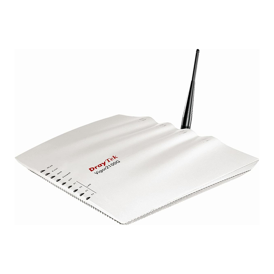
- Page 3 FXS one FXS Life Line port The Vigor2100 series are user-friendly broadband router with a built-in VoIP (Voice over IP) telephone port and/or 802.11g Wireless LAN access point. The visual design, with its stylish pleasing lines and brushed silver finish provide looks good enough to fit into any environment.
- Page 4 E-mail Detection LED flashes to indicate E-mail is Power Consumption waiting on your mail server (POP3) 15V DC 15Watt Network Features DHCP client/relay/server Dynamic DNS *future release Call schedule Radius client UPnP Preamble of DrayTek Vigor2100 Series All Rights Reserved...
- Page 5 Hardware Connection Example:Vigor2100V Preamble of DrayTek Vigor2100 Series All Rights Reserved...
- Page 6 Vigor2100 Series of Broadband Routers About This User’s Guide This manual is designed to assist users in using one of the Vigor2100 series residential broadband router with VoIP. Information in this document has been carefully checked for accuracy and, however, no guarantee is given as to the correctness of the contents.
- Page 7 Vigor2100 Series of Broadband Routers Copyright Copyright 2005 by DrayTek Corporation All rights reserved. The information of this publication is protected by copyright. No part of this publication may be reproduced, transmitted, transcribed, stored in a retrieval system, or translated into any language without written permission from the copyright holders.
- Page 8 Vigor2100 Series of Broadband Routers DrayTek Limited Warranty We warrant to the original end user (purchaser) that the routers will be free from any defects in workmanship or materials for a period of three (3) years from the date of purchase from the dealer.
- Page 9 Vigor2100 Series of Broadband Routers Be a Registered Owner Online web registration at www.draytek.com is preferred. Alternatively, fill in the registration card and mail it to the address found on the reverse side of the card. Registered owners will receive future product and update information.
- Page 10 Vigor2100 Series of Broadband Routers Safety Instructions Please read the installation guide thoroughly before you set up the router. The router is a complicated electronic device that may be repaired only be authorized and qualified personnel. Do not try to open or repair the router yourself.
- Page 11 Address: No. 26, Fu Shing Road, HuKou County, HsinChu Industrial Park, Hsin-Chu, Taiwan 303 Product: Vigor2100 Series Broadband Routers DrayTek Corp. declares that Vigor2100 series of routers are in compliance with the following essential requirements and other relevant provisions of R&TTE Directive 1999/5/EEC.
- Page 12 Vigor2100 Series of Broadband Routers Regulatory Information Federal Communication Commission Interference Statement This equipment has been tested and found to comply with the limits for a Class B digital device, pursuant to Part 15 of the FCC Rules. These limits are designed to provide reasonable protection against harmful interference in a residential installation.
- Page 13 Vigor2100 Series of Broadband Routers Customer Support Please prepare the following information as you contact your customer support. Product model and serial number. Warranty information. Date that you received your router. Brief description of your problem. Steps that you may take to solve it and their associated SysLog messages.
-
Page 14: Table Of Contents
Vigor2100 Series of Broadband Routers Table of Contents CHAPTER 1. Quick Start Wizard 1.1. Introduction..................1.2.Configure You Router via Quick Start Wizard ........CHAPTER 2. Online Status 2.1. Introduction..................2.2. Settings ....................2.2.1. System status ................... 2.2.2. LAN status..................2.2.3. WAN status .................. - Page 15 Vigor2100 Series of Broadband Routers 5.2. Settings ....................5.2.1. Port Redirection Table ..............5.2.2. DMZ Host Setup................5.2.3. Open Ports..................5.2.4. Well-known Port Number List............CHAPTER 6. Firewall Setup 6.1. Introduction..................6.2. Settings ....................6.2.1. General Setup .................. 6.2.2. Filter Setup ..................
- Page 16 Vigor2100 Series of Broadband Routers 8.2.3. CODEC/RTP/DTMF............... 8.3. Calling Scenario ................8-10 8.3.1. Voice Call Status ................8-13 8.3.2. QoS....................8-15 CHAPTER 9. Wireless Setup(for G models) 9.1. Introduction..................9.2. Settings ....................9.2.1 General Settings ................9.2.2. Seurity....................9.2.3. Access Control .................
- Page 17 Vigor2100 Series of Broadband Routers 11.2. Settings.....................11-1 11.2.1. PPPoE/PPTP Diagnostics .............11-1 11.2.2. ARP Cashe Table ................11-2 11.2.3. DHCP IP Assignment Table............11-2...
-
Page 18: Chapter 1. Quick Start Wizard
The Quick Start Wizard is designed for you to easily set up your broadband Internet access. We already integrated Quick Start Wizard into the Web Configurator of Vigor2100 series. You can directly access the Quick Start Wizard via Web Configurator. - Page 19 Quick Start Wizard Step 2. The Main Menu will pop out after completing previous step. Step 3. Now Quick Start Wizard is switched on. Enter login password. Then click Next to continue. Step 4. Select the appropriate TIME ZONE for your location.
- Page 20 Quick Start Wizard Step 5 Select the appropriate Internet connection type to your ISP. In terms of several Internet connection type, please follow procedures as below: PPPoE Users Enter your user name and password provided by your ISP. Dial on Demand: The router will ONLY connect to your ISP on demand. By “on demand”, it means when any LAN user attempt to send data onto the Internet.
- Page 21 Quick Start Wizard PPTP users Enter your user name and password provided by your ISP. Obtain an IP address automatically: Set the WAN interface as a DHCP client that will ask for the IP network settings from the DHCP server or PPTP-enabled DSL modem.
- Page 22 Quick Start Wizard Subnet Mask: an address code that determines the size of the network; this is the subnet mask of the router, when seen by external users on the Internet (including your ISP). The subnet mask is provided by your ISP. e.g.
- Page 23 Quick Start Wizard Vigor2100 V models apply efficient codecs designed to make the best use of available bandwidth. Vigor2100 V models also equips with automatic QoS assurance. QoS Assurance assists to assign higher priority to voice traffic via Internet for better talking/hearing enjoyment. To achieve that, you will always have the required inbound and outbound bandwidth that is prioritized exclusively for Voice traffic over Internet.
-
Page 24: Chapter 2. Online Status
Online Status Chapter 2 Online Status 2.1 Introduction The Online Status provides some useful information about the Vigor router, LAN and WAN interface. Also, you could use the status page to know the Internet access status. 2.2 Settings Click Online Status to open the Online Status page. Here in, we use an example to explain the Online Status. -
Page 25: Lan Status
Online Status 2.2.2 LAN Status IP Address IP address of the LAN interface. TX Packets Total number of transmitted IP packets since the router was powered RX Packets Total number of received IP packets since the router was powered Primary DNS You must specify DNS server IP address here if your ISP has the said address. -
Page 26: Chapter 3. Internet Access Setup
Internet Access Setup Chapter 3 Internet Access Setup 3.1 Introduction The router connects the group of PCs in your home or office to the Internet. The router regulates the data that travels between two networks. The Network Address Translation (NAT) of the router translates a public IP address for the Internet to several private IP addresses of a local area network. -
Page 27: Settings
Internet Access Setup 3.2 Settings For broadband access, you need to know what kind of Internet access your ISP provides. Click Internet Access to open the Internet access page. There are four widely used broadband access services, PPPoE Client, PPTP Client, Static IP for DSL, and Dynamic IP (DHCP Client) for Cable. -
Page 28: Using Pppoe With Dsl Modem
Internet Access Setup 3.2.1 Using PPPoE with a DSL modem Click Internet Access Setup > PPPoE to enter the setup page. PPPoE Setup PPPoE Link: Check Enable to enable the PPPoE client protocol on the WAN interface. Please remember to remove PPPoE applications, which are already installed on your PCs if you need to enable PPPoE and you are DSL users. -
Page 29: Using A Static Ip With A Dsl/Cable Modem
Internet Access Setup being idle for a preset amount of time. The default is 180 seconds. If you set the time to 0, the PPP session will not terminate itself. IP Address Assignment Method (IPCP) Fixed IP: Check No (Dynamic IP) unless your ISP has provided you with a static IP address. - Page 30 Internet Access Setup Access Control Broadband Access: Select Enable to turn on the broadband access capability. Keep WAN Connection Enable PING to keep alive: If you specify “Enable PING to keep alive” function, the router will periodically check your Internet connection.
- Page 31 Internet Access Setup Secondary DNS Server IP You must specify secondary DNS server IP address address here because your ISP often can let you have at least one DNS Server IP address. If you do not specify it, the router will automatically apply default secondary DNS Server IP address: 194.98.0.1 to this field.
-
Page 32: Using A Dynamic Ip (Dhcp Client)With A Dsl/Cable Modem
Internet Access Setup 3.2.3 Using a Dynamic IP (DHCP Client) with a DSL/Cable Modem This application is mostly used by Cable ISPs. Click Internet Access Setup > Static or Dynamic IP to enter the setup page. Access Control Broadband Access: Select Enable to turn on the broadband access capability. - Page 33 Internet Access Setup WAN IP Network Settings Obtain an IP address The option must be enabled. automatically Router Name Depending on your Cable ISP, this option may or may not be left blank. Some ISPs require this name for access authentication. Domain Name Depending on your Cable ISP this field may or may not be left blank.
-
Page 34: Using Pptp With A Dsl Modem
Internet Access Setup 3.2.4 Using PPTP with a DSL Modem Click Internet Access Setup > PPTP to enter the setup page, as shown below. Herein, we use an example to explain the corresponding setting. Your DSL service provider should provide the exact settings. - Page 35 Internet Access Setup PPP/MP Setup PPP Authentication Select PAP or CHAP for widest compatibility. Always On Check to force the Internet access is always online, and you will see the Idle Timeout field will be blocked for input. Idle Timeout Idle timeout means the router will disconnect after being idle for a preset amount of time.
-
Page 36: Chapter 4. Lan Setup
LAN Setup Chapter 4 LAN Setup 4.1 Introduction In this chapter, we will explain about the LAN Setup. 4.2 Settings Click LAN to open the LAN settings page. 4.2.1 LAN TCP/IP and DHCP LAN IP Network Configuration The IP address/subnet mask is for grouping users on your LAN. For example, you can let the computer of your kids be connected together with your own computer to share the broadband access and to share files. - Page 37 LAN Setup For NAT Usage: (Default: Always Enable) IP Address: Private IP address for connecting to a local private network (Default: 192.168.1.1). Subnet Mask: An address code that determines the size of the network; this is the subnet mask of the router, when seen by external users on the Internet (including your ISP).
- Page 38 LAN Setup Enable Server Let the router automatically assign IP address to every PC on the LAN Disable Server You manually assign IP address from the router to every PC on the LAN Relay Agent Allows PCs on the LAN to request IP address from other DHCP server, e.g.
- Page 39 LAN Setup automatically apply default DNS Server IP address: 194.109.6.66 to this field. Secondary IP You must specify secondary DNS server IP address here Address because your ISP often can let you have at least one DNS Server IP address. If you do not specify it, the router will automatically apply default secondary DNS Server IP address: 194.98.0.1 to this field.
-
Page 40: Chapter 5. Nat Setup
NAT Setup Chapter 5 NAT Setup 5.1 Introduction NAT is a method of mapping one or more IP addresses and/or service ports into different specified services, where NAT stands for Network Address Translation. It allows the internal IP addresses of many computers on a Local Area Network (LAN) to be translated to one public address, saving users’... - Page 41 NAT Setup and/or service ports into different specified services. In other words, the NAT function can be achieved by using port mapping method. In the Vigor routers, we support three variants of port mapping methods: Port Redirection, Open Ports, and DMZ host Port Redirection The packet is forwarded to a specific local host if the port number matches that defined in the table.
-
Page 42: Port Redirection Table
NAT Setup 5.2.1 Port Redirection Table The Port Redirection is for you to expose internal servers to the public domain. For example, you run a web server and some users want to access this web server. You also run an internal SMTP mail server for your home office and you shall allow your ISP to send whole E-mail to your SMTP mail server. - Page 43 NAT Setup Service Name Specify the name for the specific network service. Protocol Specify the transport layer protocol (TCP or UDP). Public Port Specify which port should be redirected to the internal host. Private IP Specify the private IP address of the internal host offering the service.
-
Page 44: Dmz Host Setup
NAT Setup The port redirection can only be applied to external users only - i.e. the incoming traffic. The Internet users behind your LAN can not access your external public IP address and come back in; the internal users shall access the server on its local private IP address, or you can set up an alias in a Windows hosts file. -
Page 45: Open Ports
NAT Setup Enable Check to enable the DMZ Host function. Private IP Enter the private IP address of the DMZ host. Click this button and then a window will automatically pop Choose PC up, as depicted below. The window consists of a list of private IP addresses of all hosts in your LAN network. - Page 46 NAT Setup Index Indicate the relative number for the particular entry that you want to offer service in a local host. You should click the appropriate index number to edit or clear the corresponding entry. Comment Specify the name for the defined network service. Local IP Address Display the private IP address of the local host offering the service.
-
Page 47: Well-Known Port Number List
NAT Setup Protocol Specify the transport layer protocol. It could be TCP, UDP, or NONE for selection. Specify the starting port number of the service offered by Start Port the local host. End Port Specify the ending port number of the service offered by the local host. -
Page 48: Chapter 6. Firewall Setup
Firewall Setup Chapter 6 Firewall Setup 6.1 Introduction Security is top priority to be took into consideration as the users of broadband line demands more bandwidth for multimedia, interactive applications, or distance learning. The Firewall function helps protect your local network against attack from unauthorized outsiders. It also provides a way of restricting users on the local network from accessing the Internet. -
Page 49: Settings
Firewall Setup Even your installation is not set with password; you can still enter system maintenance to set up your password. The users on the LAN are provided with secured protection by means of following firewall facilities: IP Filter Stateful Packet Inspection: tracks packets and denies unsolicited incoming data Selectable DoS/DDoS protection User-configurable packet filter... - Page 50 Firewall Setup General Setup Some general settings of Call Filter and Data Filter are available from this link. Filter Setup Here are 12 filter sets for IP Filter configurations. Dos Defense Click it to set up the DoS defense facility for detecting and mitigating the DoS attacks.
- Page 51 Firewall Setup The following sections will explain the settings in conjunction with the General Setup and Filter Setup The Vigor router provides 12 filter sets with 7 filter rules for each set. As a result, there are a total of 84 filter rules for the Filter Setup.
- Page 52 Firewall Setup The DoS Defense functionality helps you to detect and mitigate the DoS attack. Those attacks include the flooding-type attacks and the vulnerability attacks. The flooding-type attacks attempt to use up all your system's resource while the vulnerability attacks try to paralyze the system by offending the vulnerabilities of the protocol or operation system.
- Page 53 Firewall Setup URL content filter systems are seen as tools that would provide the cyberspace equivalent of the physical separations that are used to limit access to some particular materials. In rating a site as objectionable, and refusing to display it on the user's computer screen, URL content filtering facilities can be used to prevent children from seeing material that their parents find objectionable.
-
Page 54: General Setup
Firewall Setup 6.2.1 General Setup In the General Setup page you can enable/disable the Call Filter or Data Filter and assign a Start Filter Set for each, configure the log settings, and set a MAC address for the logged packets to be duplicated to. - Page 55 Firewall Setup Data Filter Check Enable to activate the Data Filter function. Assign a start filter set for the Data Filter. Log Flag For troubleshooting needs you can specify the filter log here. The log function is inactive. None Block All blocked packets will be logged.
-
Page 56: Filter Setup
Firewall Setup 6.2.2 Filter Setup Editing Filter Sets Comments Enter filter set comments/description. Maximum length 23–character long. Filter Rules Click a button numbered 1 ~ 7 to edit the filter rule. Active Enable or disable the filter rule. Next Filter Set Specifies the next filter set to be linked behind the current filter set. - Page 57 Firewall Setup Comments Enter filter set comments/description. Maximum length is 14- character long. Check to enable the Filter Rule Enables the filter rule. Pass or Block Specifies the action to be taken when packets match the rule. Block Packets matching the rule will be dropped immediately. Immediately Packets matching the rule will be passed immediately.
- Page 58 Firewall Setup Branch to other Filter Set If the packet matches the filter rule, the next filter rule will branch to the specified filter set. Duplicate to LAN If you want to log the matched packets to another network device, check this box to enable it.
- Page 59 Firewall Setup this filter rule to apply to. Operator: The operator column specifies the port number settings. If the Start Port is empty, the Start Port and the End Port column will be ignored. The filter rule will filter out any port number. = : If the End Port is empty, the filter rule will set the port number to be the value of the Start Port.
-
Page 60: Dos(Denial Of Service Defense)
Firewall Setup Fragments: Specify a fragmented packets action. Don’t care Specify no fragment options in the filter rule. Unfragmented Apply the rule to unfragmented packets. Fragmented Apply the rule to fragmented packets. Too Short Apply the rule only to packets that are too short to contain a complete header. - Page 61 Firewall Setup default values for the threshold and timeout values existing in some functions are set to 300 packets per second and 10 seconds, respectively. A brief description for each item in the DoS defense function is shown below. Enable Dos Defense Click the checkbox to activate the DoS Defense Functionality.
- Page 62 Firewall Setup Enable UDP defense Click the checkbox to activate the UDP flood defense function. Once the UDP packets from the Internet exceed the user-defined threshold value, the router will be forced to discard all sequent UDP packets in the user-defined timeout period. The default setting for threshold and timeout are 300 packets per second and 10 seconds, respectively.
- Page 63 Firewall Setup Block Land Click the associated checkbox and then enforce the Vigor router to defense the Land attacks. The LAN attack combines the SYN attack technology with IP spoofing. A Land attack occurs when an attacker sends spoofed SYN packets having the identical source and destination addresses, as well as the port number, with those of the victim.
- Page 64 Firewall Setup FINscan, Xmas scan and full Xmas scan. Block Tear Drop Click the checkbox to activate the Block Tear Drop function. Many machines may crash when receiving ICMP datagrams (packets) that exceed the maximum length. To avoid this type of attack, the Vigor router is designed to be capable of discarding any fragmented ICMP packets with a length greater than 1024 octets.
- Page 65 Syslog Setup by using Web Configurator. Thus, the administrator can look at the warning messages from DoS Defense functionality through the DrayTek Syslog daemon. The format for this kind of the warning messages is similar to those in IP Filter/Firewall except for the preamble keyword “DoS”, followed by a name to indicate what kind of...
-
Page 66: Url Content Filter
Firewall Setup 6.2.4 URL Content Filter The URL content filtering facility in Vigor routers inspects every URL string in the HTTP request initiated inside against the keyword list. If the entire or part of the URL string (for instance, http://www.ssex.com shown) matches any activated keyword, the Vigor router will block its associated HTTP request and a Syslog message will be automatically sent to the Syslog client. - Page 67 Firewall Setup Block Keyword List: The Vigor router provides 8 frames for users to define keywords and each frame supports multiple keywords. The keyword could be a noun, a partial noun, or a complete URL string. Multiple keywords within a frame are separated by space, comma, or semicolon.
- Page 68 Firewall Setup Prevent Web Access by IP Address: One checkbox is available to activate this function that will deny any web surfing activity by directly using IP address. To enable it, click on the empty box image and, subsequently, the hook image ( ) will appear. Enable Restrict Web Feature It will be of great value to provide the protection mechanism that prohibits the malicious codes from downloading from web pages.
- Page 69 Firewall Setup To enable it, click on the empty box image and, subsequently, the hook image ( ) will appear. Executable file Similar to the above function, click the checkbox to enable the Block Executable file function to reject any downloading behavior of the executable file from the Internet.
- Page 70 Firewall Setup Enable Excepting Subnets 4 entries are available for users to specify some specific IP addresses or subnets so that they can be free from the URL Access Control. To enable an entry, click on the empty checkbox, named as “ACT”, in front of the appropriate entry.
- Page 71 Syslog client in the Syslog Setup by using Web Configurator. Thus, the administrator can view the warning messages from the URL Content Filtering functionality through the DrayTek Syslog daemon. The format for this kind of the warning messages is similar to those in the...
- Page 72 Firewall Setup IP Filter/Firewall except for the preamble keyword “CF”, followed by a name to indicate what kind of the HTTP request is blocked. 6-25...
-
Page 73: Chapter 7. Application Setup
Application Setup Chapter 7 Application Setup 7.1 Introduction This section includes Dynamic DNS, Call Schedule, RADIUS setup, and UPnP settings. Before you set up the Dynamic DNS (Domain Name Server) function, you have to subscribe free domain names from the Dynamic DNS service providers. -
Page 74: Settings
Application Setup only let users of LAN to access Internet at certain times (e.g. business hours). The UPnP (Universal Plug and Play) protocol is supported to bring to network connected devices the ease of installation and configuration which is already available for directly connected PC peripherals with the existing Windows 'Plug and Play' system. -
Page 75: Dynamic Dns
Application Setup 7.2.1 Dynamic DNS Enable the Function and Add a Dynamic DNS Account 1. Assume you have a registered domain name from the DDNS provider, say hostname.dyndns.org, and an account with username: test and password: test. 2. In the DDNS setup menu, Check Enable Dynamic DNS Setup and Index number 1 to add an account for the router. - Page 76 Application Setup The Wildcard and Backup MX features are not supported for all Dynamic DNS providers. You could get more detailed information from their websites. Disable the Function and Clear all Dynamic DNS Accounts In the DDNS setup menu, uncheck Enable Dynamic DNS Setup, and push Clear All button to disable the function and clear all accounts from the router.
-
Page 77: Call Schedule
Application Setup Where A : Login Name H : Domain Name without suffix. Return Code= good 61.230.170.145 If you have any DDNS update issues, the logs are useful to find where the problem is. 3. Click Online Status to know what the current WAN IP address is. You will see the IP address in the circle, which is the same as the Return Code in the DDNS logs. - Page 78 Application Setup Click Clear All button to remove all schedules in the router. Click Cancel button to give up the current editing-operation and then return back to the Main Setup menu.
- Page 79 Application Setup Add a Call Schedule 1. Click any index, say Index No. 1. The detailed settings of the call schedule with index 1 are shown as follows. 2. The detailed descriptions for each setting are: Enable Schedule Setup: Check to enable the schedule. Start Date (yyyy-mm-dd): Specify the starting date of the schedule.
- Page 80 Application Setup Disable Specify the connection to be up when it has traffic on the line. Dial-On-Demand Once there is no traffic over idle timeout, the connection will be down and never up again during the schedule. Idle Timeout: Specify the duration (or period) for the schedule. How often Specify how often the schedule will be applied Once...
- Page 81 Application Setup An Example Suppose you want to control the PPPoE Internet access connection to be always on (Force On) from 9:00 to 18:00 for whole week. Other time the Internet access connection should be disconnected (Force Down). 1. Make sure the PPPoE connection and Time Setup is working properly.
-
Page 82: Upnp
Accordingly, you can enable either the Connection Control Service or Connection Status Service. Click the IP Broadband Connection on DrayTek Router on Windows XP/Network Connections, as shown below. The connection status and control status will be able to be activated. The NAT Traversal of UPnP enables the multimedia features of your applications to operate. - Page 83 Application Setup screenshots below show examples of this facility. The UPnP facility on the router enables UPnP aware applications such as MSN Messenger to discover what are behind a NAT router. The application will also learn the external IP address and configure port mappings on the router.
- Page 84 Application Setup Can't work with Firewall Software Enabling firewall applications on your PC may cause the UPnP function not working properly. This is because these applications will block the accessing ability of some network ports. Security Considerations Activating the UPnP function on your network may incur some security threats.
-
Page 85: Email Detection
Application Setup 7.2.4 Email detection The router can help you detect whether any new email on the assigned mail account. Up to 5 mail accounts can be set. User Name The user name or mail account name. Password The password of the mail account. POP3 Server The IP address of the POP3 mail server. -
Page 86: Chapter 8. Voip Setup (For V Models)
VoIP Setup Chapter 8 VoIP Setup (for V models) 8.1 Introduction Voice over IP network (VoIP) enables you to use your broadband Internet connection to make toll quality voice calls over the Internet. There are many different call signaling protocols, methods by which VoIP devices can talk to each other. - Page 87 VoIP Setup and G.729 A & B. Each codec uses a different bandwidth and hence provides different levels of voice quality. The more bandwidth a codec uses the better the voice quality, however the codec used must be appropriate for your Internet bandwidth. Usually there will be two types of calling scenario, as illustrated below: 1.Calling via SIP Servers First, the Vigor VoIP routers of yours will have to register to a SIP...
-
Page 88: Settings
VoIP Setup 2.Peer-to-Peer Before calling, you have to know your friend’s IP Address. The Vigor VoIP Routers will build connection between each other. Please refer to the Example 3 in the 4.3 Calling Scenario. Our Vigor2100 V models firstly apply efficient codecs designed to make the best use of available bandwidth, but Vigor2100 V models also equip with automatic QoS assurance. -
Page 89: Dialplan
VoIP Setup Voice Call Status Call Status including registered registrar, codec, connection and others. Enter upstream speed wanted to assure for VoIP call 8.2.1 DialPlan In this section, you can set your VoIP contacts in the “phonebook” we called DialPlan - help you to make calls quickly and easily by using “speed-dial”... -
Page 90: Sip Related Function
VoIP Setup Loop Through This function provides comprehensive ways to call your friend. PSTN: When the router detect your Internet connection is available, the router will dial SIP URL so your call will be directed via Internet. If the Internet connection is down, Loop Through function enable the router automatically dial Backup Phone Number so your call will be directed via PSTN network. - Page 91 VoIP Setup Please set each field in the SIP and Ports Settings accordingly. Click OK to apply settings. The detail explanation of the SIP and Port settings window: Set the port number for sending/receiving SIP message SIP Port for building a session. The default value is 5060. Your peer must set the same value in his/her Registrar.
- Page 92 VoIP Setup Set the domain name or IP address field of SIP Address, Domain/Realm e.g., every text after @. If this setting value is the same as Registrar, please press “Duplicate”. With the Registrar domain entered above, tick this box to Use Registrar let the Vigor2100 V models use the SIP Registrar.
- Page 93 VoIP Setup 8.2.3 CODEC/RTP/DTMF Default Codec Select one of five codecs as the default for your VoIP calls. The codec used for each call will be negotiate with the peer party before each session, and so many not be your default choice. The default codec is G.729A/B;...
- Page 94 VoIP Setup DTMF OutBand With OutBand selected the Vigor will capture the keypad number pressed, transform it to a digital form and send to the other side outside of the Voice stream; the receiver will generate the tone according to the digital form it receives. This function is very useful when network traffic congestion occurs to maintain the accuracy of DTMF tones.
- Page 95 VoIP Setup 8.3 Calling Scenario Calling via SIP Sever Example 1 John and David both have a SIP Address from different service providers. John’s SIP URL: 1234@draytel.org David’s SIP URL: 4321@iptel.org John’s settings David’s settings DialPlan index 1 DialPlan index 1 Phone Number: 1111 Phone Number:2222 Display Name: David...
- Page 96 VoIP Setup Example 2 John and David both have a SIP Address from the same service provider. John’s SIP URL: 1234@draytel.org David’s SIP URL: 4321@draytel.org John’s settings David’s settings DialPlan index 1 DialPlan index 1 Phone Number: 1111 Phone Number:2222 Display Name: David Display Name: John SIP URL: 4321@draytel.org...
- Page 97 VoIP Setup Peer-to-Peer Calling Example 3 Arnor and Paulin each have a Vigor2500V router, they can call each other without SIP Registrar. First they will have each other’s IP address and assign an Account Name for the port used for calling. Arnor’s SIP URL: 1234@214.61.172.53 Paulin’s SIP URL: 4321@ 203.69.175.24 Arnor’s settings...
- Page 98 VoIP Setup 8.3.1 Voice Call Status On VoIP call status, you can find the registered registrar, codec, connection and other important call status. Because Vigor2100 V models have one VoIP port for regular analogue phone set, there is one VoIP channel only. Channel Volume To adjust the volume of your VoIP calls, use these two buttons to obtain appropriate Volume Gain.
- Page 99 VoIP Setup PeerID The present in-call or out-call peer ID (the format may be IP or Domain). Connect Time The format is represented as seconds. Tx Pkts Total number of transmitted voice packets during this connection session. Rx Pkts Total number of received voice packets during this connection session.
- Page 100 VoIP Setup Also on System Status, you can find the registered registrar and codec for Inbound calls and Outbound calls. The said status easily let you check whether your registration of SIP server is successful or not. 8.3.2 QoS Enter upstream speed to let Vigor2100 V models assure high priority for VoIP call.
- Page 101 Wireless LAN Setup Chapter 9 Wireless LAN Setup(for G models) 9.1 Introduction Over recent years, the market for wireless communications has enjoyed tremendous growth. Wireless technology now reaches or is capable of reaching virtually every location on the face of the earth. Hundreds of millions of people exchange information every day using wireless communication products.
- Page 102 Wireless LAN Setup In this chapter, we explain the capabilities of the wireless LAN and its associated web configurations. Use the following setup path on the Setup Main Menu to configure the wireless LAN function. 9.2 Settings After clicking the “System maintenance System status”, you will see the following information: This web page will show the wireless LAN information including MAC address and Frequency domain and Firmware Version.
- Page 103 SSID and Channel The default SSID is "default". We suggest you change it to a particular name. In this case, SSID was changed to “DrayTek”. - SSID (Service Set Identifier): It is used to name the wireless LAN, and must have the same content in client PC/notebook wireless...
- Page 104 Wireless LAN Setup card(s). SSID can be any text numbers or various special characters. - Channel: A wireless channel for the router. The default channel is 6. You can change it to more appropriate one if the selected channel is under serious interference.
- Page 105 Wireless LAN Setup Mode Select an appropriate encryption to improve the security and privacy of your wireless data packets. - Disable: Turn off the encryption mechanism. - WEP Only: Accepts only WEP clients and the encryption key should be entered in WEP Key. - WEP or WPA/PSK: Accepts WEP and WPA clients simultaneously and the encryption key should be entered in WEP Key and PSK respectively.
- Page 106 Wireless LAN Setup WEP Encryption - 64-Bit: For 64bits WEP key, either 5 ASCII characters or 10 hexadecimal digitals leading by 0x can be entered. For example, ABCDE or 0x4142434445. - 128-Bit: For 128bits WEP key, either 13 ASCII characters or 26 hexadecimal digits leading by 0x can be entered.
- Page 107 Wireless LAN Setup MAC Address Display all MAC addresses that are edited before. Four buttons (Add, Remove, Edit, and Cancel) are provided to edit a MAC address. -ADD: Add a new MAC address into the list. -Remove: Delete the selected MAC address in the list. -Edit: Edit the selected MAC address in the list.
- Page 108 System Maintenance Setup Chapter 10 System Maintenance Setup 10.1 Introduction The System Status provides basic network settings of Vigor router It includes LAN and WAN interface information. Also, you could get the current running firmware version or firmware related information from this presentation.
- Page 109 System Maintenance Setup 10.2 Settings Click System Maintenance Setup to open the setup page. System Status Pre-settings of up to 60 SIP addresses of VoIP contacts. Administrator Password Settings of SIP port, registrar, proxy, domain and Stun server. Configuration Backup Settings of default Codec, DTMF and RTP SysLog/Mail Alert Call Status including registered registrar, codec,...
- Page 110 System Maintenance Setup 10.2.1 System Status In System Status, you will see the result shown on the right frame. In order to let you know the settings result, we design the Status bar on Set-up Menu. You can find the “Ready” indicates that you can enter settings.
- Page 111 System Maintenance Setup Click Backup button to get configurations. 3. Click OK button to save configuration as a file. The default filename is config.cfg. You could give it another name by yourself. 4. Click Save button, the configuration will download automatically to your computer as a file named config.cfg.
- Page 112 System Maintenance Setup The above example is using Windows platform for demonstrating examples. The Mac or Linux platform will appear different windows, but the backup function is still available. Restore the Configuration with a Configuration File 1. Go to System Maintenance > Configuration Backup. The following windows will be popped-up, as shown below.
- Page 113 System Maintenance Setup 3. Select the router you want to monitor. Then you will see the Syslog window. Be reminded that in Network Information, select the network adapter used to connect to the router. Otherwise, you won’t succeed in retrieving information from the router. 10-6...
- Page 114 System Maintenance Setup 10.2.5 Time Setup To specify where should the time of the router to be inquired from. Time Information Click on Inquire Time to get the current time. Time Setup Use Browser Time Select to collect time information from PC. Use Internet Time Select to inquire time information from Time Server on Client...
- Page 115 System Maintenance Setup Management Setup The port number used to send/receive SIP message for building a session. The default value is 5060 and this must match with the peer Registrar when making VoIP calls. Enable remote Chick the checkbox to allow remote firmware upgrade firmware update through FTP (File Transfer Protocol).
- Page 116 In the following, we use an example to explain the firmware upgrade. Note that this example is running over Windows OS (Operating System). 1. Download the newest firmware from DrayTek' s web site or FTP site. The DrayTek web site is www.draytek.com (or local DrayTek' s web site) and FTP site is ftp.draytek.com...
- Page 117 System Maintenance Setup Click the Browse button to locate the new firmware file. The program will look for any Vigor routers on your LAN and display them by IP address. Select the ‘IP address’ of the appropriate router to upgrade, then press Upgrade.
- Page 118 Diagnostic Setup Chapter 11 Diagnostics Setup 11.1 Introduction Diagnostic Tools provide a useful way to view or diagnose the status of you Vigor router. 11.2 Settings Click Diagnostics to open the setup page. 11.2.1 PPPoE/PPTP Diagnostics Refresh To obtain the latest information, click here to reload the page.
- Page 119 Diagnostic Setup 11.2.2 ARP Cache Table Click View ARP Cache Table to view the content of the ARP (Address Resolution Protocol) cache held in the router. The table shows a mapping between an Ethernet hardware address (MAC Address) and an IP address. Refresh: Click it to reload the page.