
Related Manuals for Simrad AP25


Summary of Contents for Simrad AP25
- Page 1 Manual Simrad AP25 Autopilot for Volvo Penta IPS system English Sw.1.2 www.simrad-yachting.com A brand by Navico - Leader in Marine Electronics...
-
Page 2: Instruction Manual
Instruction manual Instruction Manual This manual is intended as a reference guide for operating and correctly installing the AP25 autopilot in a Volvo Penta IPS system. Great care has been paid to simplify operation and set-up of the Simrad AP25 Autopilot. Set-up is significantly simplified when the autopilot is interfaced to the Volvo system. - Page 3 Simrad AS. The information contained in this document is subject to change without prior notice. Simrad AS shall not be liable for errors contained herein, or for incidental or consequential damages in connection with the furnishing, performance, or use of this document.
-
Page 4: Table Of Contents
System description ..................7 1.1 General ....................7 1.2 How to use this manual................. 7 1.3 System components................8 1.4 AP25 Control Unit ................9 1.5 Autopilot Computer ................9 1.6 Heading Sensor ..................9 1.7 Optional equipment................9 R3000X Remote Control ..............9 JS10 Joystick.................. - Page 5 2.12 Thruster Steering (optional) ..............28 2.13 NoDrift ....................30 Dodge in NoDrift mode ..............30 2.14 Navigating with the AP25..............31 Setting the waypoint arrival circle ............33 2.15 Dodge in NAV ..................34 2.16 Selecting a different Navigation source..........35 2.17 Multiple station system ...............
- Page 6 Instruction manual 3.8 ROBNET2 network cables ..............55 AP27 connection ................. 57 3.9 RC36 Rate Compass installation ............57 3.10 R3000X Remote Control installation ..........59 3.11 JS10 Joystick..................60 3.12 S35 NFU Lever installation ..............60 3.13 Interfacing ................... 60 3.14 SimNet....................
- Page 7 Trouble shooting ..................91 6.1 Alarms ....................91 Spare Parts List..................95 Technical Specifications ................98 8.1 AP25 Autopilot System ..............98 8.2 AP25 Control Unit ................100 8.3 AC05 Autopilot Computer..............101 8.4 RC36 Rate compass ................102 8.5 R3000X Remote Control ..............103 8.6 JS10 Joystick..................
-
Page 8: System Description
The autopilot system can be expanded and enhanced with a selection of options and accessories. The brain in the AP25 autopilot system is the single "intelligent" autopilot computer that communicates on the proprietary Robnet2 network to establish a reliable digital communication and power distribution network between the units in the autopilot system. -
Page 9: System Components
This must be filled out by the authorized dealer that performed the installation and mailed in to activate the warranty. System components A basic AP25 system consists of the following units (refer to Figure 1-1): • AP25 Control Unit with accessories • AC05 Autopilot Computer •... -
Page 10: Ap25 Control Unit
Simrad products. A NMEA2000 Adaptor Cable is available for interface through a SimNet port (page 96). Autopilot Computer The AC05 Autopilot Computer is the heart in the AP25 autopilot system. It contains the steering computer, interface to other system components, and interface to Volvo Penta IPS system. -
Page 11: Ti25 Thruster Interface
TI25 Thruster Interface The TI25 Thruster Interface is designed to provide a control signal for operating a thruster interfaced to an AP25 system. It operates on/off solenoids, or a Danfoss PVEM valve. The Danfoss valve is a proportional valve that will provide full thruster performance with the output from TI25. -
Page 12: Operation
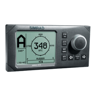
• Always switch to Standby mode and reduce speed in due time to avoid hazardous situations Overview Multifunction LCD PORT key STANDBY mode/POWER on/off TURN/ DODGE key AUTO mode STARBOARD key NAV or NoDrift mode Course knob INSTRUMENT screens/ setup menus Figure 2-1 AP25 Front Panel 20222139A... -
Page 13: On/Off - Standby Mode
WIND mode is not applicable, hence not available in a Volvo Note ! Penta IPS configuration. A group of user adjustable settings are provided in the AP25 User Setup Menu (page 37). Alarms are presented in plain text to alert you of system and external data failure conditions. -
Page 14: Flashing Course Knob Icon
Operation After approximately 5 seconds, the following message is displayed: The system is now operative and the unit that was turned on will show the Standby mode display. Other units in a multistation system will display "Inactive". Control is transferred to any single unit by pressing its’... -
Page 15: Alarms
Simrad AP25 Autopilot Alarms In the event there is an audible alarm with explaining text on the control unit, refer to section 6, Trouble shooting. Follow-Up steering (FU) In the Follow-Up steering mode the course knob may be used to set rudder commands. -
Page 16: R3000X Remote Control (Nfu)
Note ! control units become "Inactive". Automatic Steering When AUTO mode is selected, the AP25 automatically picks the current boat heading as the set course and maintains the simultaneous rudder angle. This gives a bumpless transfer at the mode change. -
Page 17: Heading Capture
Steering parameter: LO-A The AP25 will keep the boat on the set course until a new mode is selected or a new course is set with the course knob or the PORT or STBD buttons. One revolution of the course knob equals a 45°... -
Page 18: Automatic Control Of Steering Parameters
HI automatically by input data from a speed log or a GPS navigator (SOG), or manually. The speed at which the AP25 automatically changes from LO to HI parameters (or opposite) is determined by the "Transition Speed" set in the Installation Setup Menu (Sea trial). See diagram below. -
Page 19: Manual Selection Of Hi/Lo Parameters
Simrad AP25 Autopilot Speed Transition to LO parameters with increasing speed: 10 Knots Transition Speed set to 9 Knots Transition to HI parameters with decreasing speed: 8 Knots Manual Selection of HI/LO Parameters Manual selection of HI/LO parameters is necessary if there is no speed input to the autopilot or if you want to override the automatic control. -
Page 20: Pattern Steering
PORT or STBD button to select the direction to make the U-Turn. If you do not press PORT or STBD within 1 minute, the AP25 will return to the AUTO mode and stay on course. - Page 21 Then select C-turn by another press of the TURN/DODGE button. The AP25 will continue on the set course until you press either the PORT or STBD button to select the direction in which to make the C-turn. If you do not...
-
Page 22: Spiral-Turn
Adjustable range is 10 to 600°/min. The AP25 will continue on the set course until you press either the PORT or STBD button to select the direction in which to make the spiral turn. If you do... -
Page 23: Zigzag-Turns
The course change can be set before the turn is initiated. The AP25 will continue on the set course until you press either the PORT or STBD button to select the direction in which to make the first course change. If... -
Page 24: Square-Turn
The time between each 90° course change can be adjusted before the turn is initiated. The AP25 will continue on the set course until you press either the PORT or STBD button to select the direction in which to make the first course change. -
Page 25: Lazy S-Turn
Simrad AP25 Autopilot Lazy S-turn The AP25 also provides a lazy S-turn feature when in AUTO mode. The user decides whether the initial turn should be made to Port or to Starboard. Ensure that the lazy S-turn pattern has been selected under the User Set-up 2 menu. -
Page 26: Depth Contour
Operation Depth Contour Steering to a depth contour is also an AUTO mode feature. With input from an echo sounder, the autopilot can be set to steer the boat to a set depth. This is very useful if you want to follow a depth contour. - Page 27 Simrad AP25 Autopilot Select depth slope with the course knob. “/” means shallow is to starboard, “\” means shallow to port. Steer the boat to the depth you want to track and in the direction of the depth contour (main course).
-
Page 28: Dodge In Auto
When in DODGE mode the displayed set course is the last one set prior to activating the dodge function. When DODGE is displayed, the AP25 is no longer in control of the steering, and you must either manually steer the boat in STBY mode or take control using Non Follow Up or Follow Up steering. -
Page 29: Thruster Steering (Optional)
2.12 Thruster Steering (optional) If the boat is equipped with an appropriate thruster (page 10), it can be connected to the AP25 system and the boat can then be controlled by rudder and thruster. When the AP25 is controlling the thruster you may: •... - Page 30 Operation Examples of display pictures: STANDBY Non-Follow Up steering mode Heading to be Heading to be maintained by rudder maintained by rudder and thruster AUTO mode Heading maintained Heading maintained by rudder by rudder and thruster When operating an On/Off thruster be aware that most electrical Note ! thrusters have a built in thermal cut-off switch.
-
Page 31: Nodrift
Simrad AP25 Autopilot 2.13 NoDrift The NoDrift mode is an alternative to route steering in NAV mode, and is automatically entered when you press the NAV WIND button provided NoDrift has been selected in the (user) SETUP menu (page 38). -
Page 32: Navigating With The Ap25
Waypoint shift. Note ! If the AP25 is connected to a navigation receiver that does not transmit a message with bearing to next waypoint, it will pick a XTE message and steer on Cross Track Error only. In that case... - Page 33 GPS/chart plotter. Three decimals give a more accurate track keeping. When operating the AP25 in NAV mode to steer through a route of waypoints, the AP25 will steer to the first waypoint in the route after you accept the first waypoint as the location to steer towards.
-
Page 34: Setting The Waypoint Arrival Circle
Alert screen. Press NAV button to verify course change larger than 10°. If no verification is received, the AP25 will continue on the current set course in AUTO mode. Regain manual steering by pressing the STBY button Setting the waypoint arrival circle For route navigation it is recommended to use automatic waypoint shift/change at a set waypoint arrival circle. -
Page 35: Dodge In Nav
Steer (CTS) is the boat’s recommended heading. However, the previous set course is stored by the AP25. When DODGE is flashing on the display, the AP25 is no longer in control of the steering and you must either steer the boat manually or take control using either Non-Follow-up steering or Follow-up steering. -
Page 36: Selecting A Different Navigation Source
2.16 Selecting a different Navigation source If you have more than one navigation source connected to the AP25, you will be able to choose any for navigation. Refer to the “Source select” item in the User Set-up 2 menu for details on selecting a different navigator (page 38). -
Page 37: Lock Function
Simrad AP25 Autopilot 2.18 Lock function The "LOCK" function is a safety feature in the AP25 system. It will disable all control units, including the FU25 Follow-up lever, except for a single user selected control unit location. When the "lock" function is in use, no transfer of command can take place;... -
Page 38: User Set-Up Menu
Operation 2.19 User Set-up Menu In the AP25, all modes except NFU and FU have a complemental User Set-up menu. You can easily access the set-up menu by a quick double press on the INFO/SETUP button. Use the course knob... - Page 39 Simrad AP25 Autopilot NAV WIND This setup will configure the active mode under the NAV WIND button. The following alternatives are available: • NAV (Ref. page 31) • NoDrift (Ref. page 30) WIND is not an applicable mode on boats with the Volvo IPS Note ! installed.
- Page 40 – – indicates that no source supplying the data is available. Notes ! 1. Simrad products will be identified by the product name provided the data is available on SimNet. If speed data is provided from the Volvo IPS system to the autopilot computer, the display will read IPS.
- Page 41 Select the source for Wind Angle. Wind Calculated Select the source for Calculated Wind data for the Simrad group. The autopilot uses internal source irrespective of the selected source. Water Speed Select the source for water speed (normally the same as the source providing Log data).
- Page 42 Operation Note ! The shallow water alarm is activated only when digits are dialled in. Course Adjust When using the (PORT) or (STBD) buttons in AUTO mode, you are changing the set course in 1° increments. If you prefer the increments to be 10° each press, proceed as follows: Select Course adjust and turn the course knob to change the setting.
-
Page 43: Auto Mode
Other relevant settings are described under STANDBY mode in this chapter. Response The Autotune function in the AP25 is so refined that 80-85 % of the boats will need no further adjustments of the steering parameters. On some boats, however, or at particular sea conditions a fine tuning of the steering parameters may improve the performance of the autopilot. -
Page 44: Nav Mode
Operation Seastate filter OFF: Seastate filter is disabled. AUTO: Automatically reduces rudder activity and autopilot sensitivity in rough weather by an adaptive process (default). MANUAL: Manual yaw band adjust (1-10, 10 ≈ ±6°). The manual setting determines the number of degrees the vessel may deviate from the set course before any command is given to the rudder. -
Page 45: Info Menu
Simrad AP25 Autopilot 2.20 INFO menu A number of instrument pages are available under each mode screen if the required information is available on SimNet (page 85). The INFO menu is accessed by a single press on the INFO/SETUP button. -
Page 46: Course Knob Icon
Operation If you prefer not to have all the instrument pages available in the INFO menu, you may remove pages under the User setup 2 menu. See page 41. Return to last instrument screen by a simple press on the INFO button. -
Page 47: Info Menu Flowchart
Simrad AP25 Autopilot INFO menu flowchart 3-5 sec. time-out Toggle 3-5 sec. time-out 20222139A... -
Page 48: Info Menu And Main Screen, Active Unit
Operation INFO menu and Main Screen, active unit INFO-menu Main screen 3-5 sec. time out INFO menu and Main Screen, inactive or locked unit Previous INFO page Next INFO page Last shown INFO page 20222139A... - Page 49 Simrad AP25 Autopilot This page is intentionally left blank. 20222139A...
-
Page 50: Installation
This section provides detailed information required to successfully installing the AP25 Autopilot system. A basic AP25 system includes only three modules that need to be mounted in different locations on the boat, and also need to interface with at least three different systems on the boat: •... -
Page 51: Unpacking And Handling
An AP25 autopilot system for Volvo Penta IPS will include: • AP25 Control unit with standard installation accessories and one 10 m (33') Robnet2 cable •... -
Page 52: Ap25 System Layout
Installation AP25 System Layout Figure 3-1 AP25 system layout with options Autopilot computer installation The autopilot computer is designed to operate in a location with ambient temperatures below +55°C (+130°F). Note ! The AC05 Autopilot Computer is not weatherproof and should be mounted vertically in a dry environment. -
Page 53: Cable Connections
Simrad AP25 Autopilot Cable connections Use only shielded cables, also for the Mains input. Signal cables should be 0.5 mm (AWG20) twisted pairs. The mains supply cable should have sufficient wire gauge; minimum 1,5 mm (AWG14). Grounding and RFI The autopilot system has excellent RFI protection. The autopilot computer should have a proper ground connection to the hull/bonding system. -
Page 54: Cable Strain Relief
Installation Cable strain relief Once all the cables have been run to the appropriate peripherals and connected to the autopilot computer unit they should be secured to ensure that they are not snagged or exposed to excess strain. Screw the strain relief tab to the cable exit port on the autopilot computer unit using the screws supplied and secure the cables to the tab using the wraps as shown. -
Page 55: Control Unit Installation
Alternative panel mounting This way of mounting may be simpler, but will lift the unit from the panel surface. When installed adjacent to Simrad equipment there will be a 5,5 mm (0,22”) difference in height between the autopilot and the other equipment. -
Page 56: Optional Bracket Mounting
• Connect the Robnet2 cable(s) to the control unit connector(s) (See note on page 56). Figure 3-4 AP25 Bracket mounting ROBNET2 network cables As Robnet2 units have two Robnet2 connectors (blue) they can be used as "jack points" for further expansion of the system. - Page 57 Simrad AP25 Autopilot available in 1, 5 and 10 m length. For cable extension a Robnet2 T-Joiner is required. When installing a system, try to minimize total Robnet2 cable length by connecting all Robnet2 units to the nearest available Robnet2 connector.
-
Page 58: Ap27 Connection
IPS system. The gateway kit must be ordered from Volvo under P/N 3819744. AP27 connection If a Simrad AP27 is part of the system, use the JP27 Jack Point and connect as shown on Figure 3-5. The AP27 cable contains an air-breathing tube. Check that the Note ! cable runs free to avoid blocking of the tube. - Page 59 Simrad AP25 Autopilot The heading sensor is the most important part of the AP25 system and great care should be taken when deciding the mounting location. As the heading is displayed on the AP25 Control Unit, the heading sensor can be mounted at a remote location.
-
Page 60: R3000X Remote Control Installation
Installation RATE COMPASS AP16, AP25, AP26 Figure 3-9 RC36 connection to autopilot control unit Plug the RC36 into a Robnet2 connector (see Figure 3-5). 3.10 R3000X Remote Control installation R3000X should be mounted in the supplied bracket that can be fixed by four mounting screws. -
Page 61: Js10 Joystick
Inside are two sets of micro-switches, a printed circuit board with a plug-in terminal and a jumper strap. 3.13 Interfacing With the AP25 autopilot system there are several possibilities to connect to other equipment for data collection and exchange. 1. Use SimNet 2. -
Page 62: Simnet
Installation 4. The AC05 has high speed compass heading output to Simrad and Furuno radars (Clock/Data interface). The different connecting diagrams on the following pages illustrate the interface possibilities of the AP25 autopilot. 3.14 SimNet The SimNet cable system with very small plugs in both ends makes it easy to run the cables, only 10 mm (3/8”) holes are... - Page 63 Simrad AP25 Autopilot 4. SimNet will power an IS12 instrument system. Hence SimNet on other equipment can be connected and powered via IS12. 5. SimNet must be properly terminated. The SimNet network has to be terminated according to the number and type of products connected.
- Page 64 Installation The wind transducer (*) has a built in terminator. COM BI COM BI COM BI DATA SIM RA D IS1 2 SIM RAD IS12 SIM RA D IS1 2 SIM RAD IS12 UPPER LOWER LIGHT ALARM UPPER LOWER LIGHT ALARM UPPER LOWER...
- Page 65 Simrad AP25 Autopilot Figure 3-15 Robnet2 and SimNet network * The wind transducer has a built in terminator 20222139A...
- Page 66 Installation Figure 3-16 Robnet2, SimNet and Roblink network Notes ! 1. Maximum total length of SimNet cable is 60 m (196 ft.) excluding the 30 m (99 ft.) of masthead cable. 2. It is not necessary to connect all autopilot control units to SimNet for data sharing.
-
Page 67: Radar Clock/Data Heading Output
Simrad AP25 Autopilot 3.15 Radar Clock/Data Heading Output SIMRAD/ANRITSU AUTOPILOT COMPUTER FURUNO RADAR T B 4 R A D A R Figure 3-17 Radar Clock/Data connection 3.16 IS15 Instrument installation For installation and operation of the IS15 instruments refer to separate manuals. -
Page 68: Configuration And Setup
Configuration and Setup 4 CONFIGURATION AND SETUP First time turn on Before attempting to turn on the AP25 and perform an Installation Setup, the hardware installation and electrical connections must be completed in accordance with the installation instructions. The design of the AP25 includes advanced features that have simplified the installation and setup of an autopilot. -
Page 69: Description Of Installation Settings
Some important points regarding the installation settings: • When the AP25 is delivered new from the factory AND ANY TIME AFTER A MASTER RESET OF MEMORIES HAS BEEN PERFORMED, the installation settings are all reset to factory preset (default) values. -
Page 70: Installation Menu
Configuration and Setup • The Installation Settings are global except for display units and language, enabling settings to be distributed to all control units in the system. Installation Menu The Installation Menu is presented on the autopilot display by pressing and holding the INFO/SETUP button for 5 seconds. - Page 71 Simrad AP25 Autopilot ENTER INSTALLATION MENU INSTALLATION SYMBOLS BY PRESSING AND HOLDING THE MENU NAV BUTTON FOR 5 SECONDS SELECT OR CONFIRM BY COURSE KNOB LANGUAGE MENU PROCEED TO NEXT MENU ITEM LANGUAGE ENGLISH BY PRESSING STBD BUTTON DEUTSCH FRANCAIS...
-
Page 72: Language Selection
Configuration and Setup Language selection To access the language selection in the Installation Menu, confirm “Yes” by turning the course knob clockwise The AP25 can present the display text in eight different languages: English, Deutsch, Francais, Espanol, Italiano, Nederlands, Svenska and Norsk. -
Page 73: Display Units
Available units are: Wind Speed: kt or m/s Sea temperature: °C or °F Depth: m or ft Exit the Display units menu by pressing STBD button to proceed to the Sea trial menu, or press STBY to return to normal AP25 operation. 20222139A... -
Page 74: Sea Trial
Configuration and Setup Sea Trial WARNING ! The Sea Trial must always be performed in open waters at a safe distance from other traffic. The seatrial settings are: • Compass calibration (To automatically compensate for onboard magnetic interference) • Compass Offset (To compensate for a fixed offset (A-error) in the final compass heading readout) •... -
Page 75: Compass Calibration
Simrad AP25 Autopilot Compass calibration This function will activate the compass calibration procedure for Simrad compasses connected to Robnet2. Notes ! The RC36 Rate Compass that comes with the autopilot as standard will store the calibration and off-set data in its own memory. -
Page 76: Compass Offset
Configuration and Setup Compass deviation The heading from a magnetic heading sensor will normally have a deviation when compared with the actual direction of the earth’s magnetic field. This is caused by interference from the boat’s local magnetic field. The deviation will be at a minimum if the compass is placed as far as possible from any magnetic object on board. - Page 77 Simrad AP25 Autopilot Note ! Offset correction is always performed after the calibration. If you use COG as a reference for the offset remember it has to be a magnetic reading. The compass OFFSET feature allows you to correct for a fixed heading offset.
-
Page 78: Set Thrust Direction
Configuration and Setup Set Thrust Direction (Only applicable if a thruster is connected) Rotate the course knob clockwise to activate the Set thrust direction setting. Rotate the course knob CW and verify that the vessel turns to starboard. The thruster stops after 10 seconds, or when the STBD button is pressed. -
Page 79: Wind Damping
Simrad AP25 Autopilot Wind damping Damping of the apparent wind angle is made by the Advanced Wind Filter (AWF) in the Autopilot Computer. The inputs to the AWF are heading, boat speed, apparent wind angle and wind speed. Verify that these inputs are available in User Setup2/Source Select. -
Page 80: Automatic Tuning
S-turns. Automatic tuning is an optional procedure that is not required for the AP25 to function. The AP25 is preset with steering parameters that should steer most boats in the 30 - 80 foot range. -
Page 81: Transition Speed
Proceed to the next menu item by pressing the STBD button, or return to Standby mode by pressing the STBY button. Transition Speed The transition speed is the speed where the AP25 will automatically change the steering parameter set from HI to LO parameters, or vice versa (page 17). -
Page 82: Init Nav
Configuration and Setup Init NAV Sets a firm or soft approach to the track line when entering the NAV mode at the first leg. The approach angle is dependant (adaptive) on the distance (XTE) from the track line and the boat speed. -
Page 83: Manual Parameter Adjust
Simrad AP25 Autopilot Manual parameter adjust Use course knob to Displayed Automatic Default Manual adjust parameters parameter tuning Rudder LO 0.20 Cont.Rudder LO 1.00 Autotrim LO 40 sec. HIgh Use PORT and Rudder HI 0.30 STBD buttons to Cont.Rudder HI 1.40... - Page 84 Configuration and Setup • Low speed requires more Rudder than high speed. Counter Rudder is the parameter that counteracts the effect of the boats turn rate and inertia. For a short time period it is superimposed on the proportional rudder response as provided by the heading error.
-
Page 85: Recall Autotuned
Confirmed is displayed. Exit the Parameter menu by pressing STBD button to proceed to the Service menu, or press STBY to return to normal AP25 operation. Service Menu Select STANDBY mode and then enter the Installation Menu by pressing and holding the INFO/SETUP button for 5 seconds. -
Page 86: Simnet Data Screen
SimNet messages used by the system. Decoding The incoming signals are decoded according to a built in priority table in the AP25. For all data items, one of the following codes will be displayed: – – – No data. -
Page 87: Simnet Setup
Simrad AP25 Autopilot Simnet setup Group selection SIMRAD: Autopilot is part of the Simrad Group. Source selection will be common for the products in the group (synchronized). STAND ALONE: Source selection for the autopilot will not be transferred to other products in the Simrad Group (no synchronization). -
Page 88: Master Reset
• If a Non-Follow Up lever (or handheld remote) is connected, test change of modes and verify port and starboard steering commands of the lever. • Set waypoints into each navigator connected to the system, and verify that the AP25 steers in NAV mode for each NAV source. 20222139A... -
Page 89: Providing User Training
Simrad AP25 Autopilot • Try the NoDrift mode. • Provide the owner with user training. Providing user training The user should be instructed in the "basic" operational functions, such as: • Turning the system on and off • Changing modes. Explain briefly what takes place in the different modes. -
Page 90: Maintenance
Maintenance 5 MAINTENANCE Control unit The AP25 Control Unit will under normal use require little maintenance. If the unit requires any form of cleaning, use fresh water and a mild soap solution (not a detergent). It is important to avoid using chemical cleaners and hydrocarbons such as diesel, petrol etc. -
Page 91: Exchange Of Software Programme
Simrad AP25 Autopilot Exchange of software programme You will need a special kit for a PC to perform the programming of the AC05 Autopilot Computer and the AP25 Control Unit. Order the following from Simrad: Programming kit P/N 22088595. Instructions are included. -
Page 92: Trouble Shooting
An autopilot is a complex system. Its performance dependents on a proper installation and a successful sea trial. In the event of an autopilot failure, the AP25’s numerous test features will assist you in isolating a probable fault. Audible and visual alarm is provided for every fault being detected. - Page 93 Simrad AP25 Autopilot Display readout Probable fault Recommended action Compass data No data from 1. If more that one compass is missing selected compass. connected to the system, refer to the User Setup2/Source select menu to select a different compass.
- Page 94 Trouble shooting Display readout Probable fault Recommended action High supply Supply voltage 1. Verify in the System Data Menu voltage exceeds 31,2 V 2. Switch the autopilot off 3. Check / repair battery charger No thruster The thruster interface See TI25 Thruster Interface manual response unit is not responding Trouble shooting.
- Page 95 Simrad AP25 Autopilot 20222139A...
-
Page 96: Spare Parts List
22084768 Cradle 22084776 Right bracket 22084784 Left bracket 22084859 Locking knob 44163145 Locking washer for left and right bracket 44163160 Cradle, locking washer 22087829 AP25 Front Housing Ass’y 22087894 Back cover with gasket 22087738 AP25 Board Ass'y 22084750 Protection Cover 22088199... - Page 97 Simrad AP25 Autopilot 44133601 Plug-in Terminal 5-way 44135333 Plug-in Terminal 2-way 22089304 AC05 Software RC36 Rate compass 22086920 RC36 Rate Compass 22081442 Installation Accessories Consisting of: 20104972 Mounting plate (2) 44140762 Screw 3.5x25 (2) 44140770 Screw 30x9 (4) 22081376 Plug (2)
- Page 98 Spare parts list 24005729 SimNet cable to Micro-C. Adapter (drop) cable for SimNet products in a NMEA2000 network. 24006199 Interconnection cable to Volvo IPS 1.0 m (3’) 20222139A...
-
Page 99: Technical Specifications
Language selection: ....English, Norwegian, French, Spanish, German, Italian, Dutch, Swedish. Electronic Interface: Navigation interface:..Standard (NMEA 0183) via AT10 Compass heading output: . Simrad and Furuno radar display (clock/data) NMEA2000 interface..Via SimNet port and SimNet/NMEA2000 adapter cable Heading sensors: Standard: ...... - Page 100 Technical specifications Special Turn modes: ....Dodging, U-Turn, C-Turn, Spiral, Zigzag, Square, Lazy S, Depth contour. Instrument screen interface: Instrument screen NMEA0183 messages and SimNet MAIN (HDG+RUDDER) ROBNET2 PROPRIETARY, NMEA HDT and HTG, SimNet SPEED/DEPTH VHW + DBT/DPT, SimNet APPARENT WIND MWV, SimNet TRUE WIND/WIND MWV + VTG/RMC;...
-
Page 101: Ap25 Control Unit
Safe distance to compass: ..0.5 m (1.6 ft.) Temperature: Operating: ......0 to +55 °C (+32 to +130 °F) Storage: ......–30 to +70 °C (–22 to +158 °F) Figure 8-1 AP25 Control Unit – dimensions (Mounting bracket is optional equipment) 20222139A... -
Page 102: Ac05 Autopilot Computer
Technical specifications AC05 Autopilot Computer Dimensions: ....... See Figure 8-2 Weight: ........1,1 kg (2,4 lbs) Supply voltage:......10.8 - 31.2 VDC Reverse voltage protection ..Yes Environmental Protection:..IP22 Safe distance to compass: ..1.0 m (3 ft.) Power consumption: ....5 Watt (electronics) External Alarm: ...... -
Page 103: Rc36 Rate Compass
Simrad AP25 Autopilot RC36 Rate compass Dimensions: ....... See Figure 8-3 Weight: ........0,9 kg (2,0 lbs) Supply and interface:....Robnet2 Power consumption: ....0,9 watts Automatic Performance: Calibration: ....... Automatically activated by control head Gain compensation: ..Automatically adjusted continuously Rate sensor stabilized heading output Accuracy:........ -
Page 104: R3000X Remote Control
Technical specifications R3000X Remote Control Dimensions: ..See Figure 8-4 Weight:.... 0,4 kg (0,9 lbs) Material:..Epoxy coated aluminium Protection ..IP56 Safe distance to compass: 0.15 m (0.5 ft.) Temperature range: Operation: ...–25 to +55 °C (–13 to +130 °F) Storage: ..–30 to +70 °C (–22 to + 158 °F) Cable length: ... -
Page 105: Simnet
Simrad AP25 Autopilot SimNet Maximum number of products connected in a network:........50 Maximum cable length: ..............120 m (400’) Bit rate of the bus: .................250 Kbit/second Maximum DC current through a single SimNet plug ......... 5A SimNet power supply: ................12VDC Maximum drop cable length:.. -
Page 106: Ip Protection
Technical specifications IP protection Each part of a Simrad autopilot system has a two digits IP protection code. The IP rating is a method to classify the degree of protection against solid objects, water ingress and impact afforded by electrical equipment and enclosures. The system is recognised in most European countries and is set out in a number of British and European standards. -
Page 107: Simnet Messages
Simrad AP25 Autopilot SimNet messages SimNet/NMEA2000 messages and data overview Message ident. Data source: N=nav, P=pos, H=heading, D=depth, Wa=Wind apparent, P P P P P P Wt=Wind True, WaS=Water Speed/ WaT=Water temp, Dl=Distance log, C=Calculated) Compass Data Compass heading Rudder Data... - Page 108 Technical Specifications Remarks: Indata use * SimNet proprietary x In INFO views Depth+Offset is displayed if x offset is present *Only transmitted if NMEA183/RC36/RFC35 is source x* x* x* 20222139A...
-
Page 109: Glossary
Simrad AP25 Autopilot 9 GLOSSARY Apparent wind – The speed and direction from which the wind appears to blow with reference to the bow when the boat is moving (also called relative wind). Arrival alarm – An alarm signal issued by a GPS/chartplotter that indicates arrival at or at a predetermined distance from a waypoint. - Page 110 SimNet controller. When connected to SimNet they will automatically pick the first available source on SimNet and lock on to that. When a Class 1 product is added to the Simrad Group, Class 2 products will automatically subordinate themselves to the Class 1 source selection.
- Page 111 Simrad AP25 Autopilot True bearing – Bearing relative to true north; compass bearing corrected for compass error. True heading – Heading relative to true north (the meridian). Waypoint - A discrete point, stored in a navigator, located on the surface of the earth. Normally this point will be identified by Lat/Lon coordinates although in some systems it may be shown by T.D.'s.
-
Page 112: Index
Index 10 INDEX alarm depth offset, 78 external, 66 depth source, 40 apparent wind, 108 depth unit, 72 arrival circle, 33 depth-turn, 25, 41 auto source update, 39 deviation, 75 automatic tuning, 79 display units, 72 autopilot computer dodging, 27 installation, 51 maintenance, 89 autotrim, 83... - Page 113 Simrad AP25 Autopilot specifications, 101 setting, 82 language, 71 sea trial, 87 lazy S-turn, 24, 41 seastate filter, 43 lock function, 36 shallow water, 40, 43 log source, 40 SimNet, 7, 9, 39, 61 backlight, 86 gateway, 86 number, 86...
- Page 114 Index wind damping, 78 user training, 88 offset, 77 U-turn, 19, 41 wind angle source, 40 wind calculated source, 40 wind speed unit, 72 water speed source, 40 water temperature source, 40 water temperature unit, 72 zigzag-turn, 22, 41 20222139A...
- Page 115 Simrad AP25 Autopilot This page is intentionally left blank 20222139A...