
Related Manuals for Simrad AP26


Summary of Contents for Simrad AP26
- Page 1 Manual Simrad AP26 and AP27 Autopilots for Volvo Penta IPS system English Sw.1.2 www.simrad-yachting.com A brand by Navico - Leader in Marine Electronics...
-
Page 2: Instruction Manual
Instruction manual Instruction Manual This manual is intended as a reference guide for operating and correctly installing the AP26 and AP27 autopilots in a Volvo Penta IPS system. Great care has been paid to simplify operation and set-up of the autopilots. - Page 3 Simrad AS. The information contained in this document is subject to change without prior notice. Simrad AS shall not be liable for errors contained herein, or for incidental or consequential damages in connection with the furnishing, performance, or use of this document.
-
Page 4: Table Of Contents
System description ..................9 1.1 General ....................9 1.2 How to use this manual................. 9 1.3 System components................10 1.4 AP26 Control Unit ................11 1.5 AP27 Control Unit ................11 1.6 Autopilot Computer ................11 1.7 Heading Sensors.................. 12 1.8 Optional equipment................ - Page 5 2.12 Thruster Steering (optional) ..............33 2.13 NoDrift ....................35 Dodge in NoDrift mode ..............35 2.14 Navigating with the AP26 and AP27..........36 Setting the waypoint arrival circle ............38 2.15 Dodge in NAV ..................39 2.16 Selecting a different Navigation source..........40 2.17 Multiple station system ...............
- Page 6 Grounding and RFI ................56 Cable strain relief ................57 3.7 Control unit installation ..............58 Panel mounting of AP26..............58 Alternative panel mounting of AP26 ..........58 Optional bracket mounting ..............59 3.8 ROBNET2 network cables ..............59 AP27 connection ................. 61 3.9 RC36 Rate Compass installation ............
- Page 7 Simrad AP26 and AP27 Autopilots 4.6 Sea Trial ....................76 Compass calibration................77 Compass Offset ................... 79 Set Thrust Direction ................80 Wind Offset..................80 Wind damping..................80 Depth Offset..................81 Automatic tuning................. 81 Transition Speed ................. 82 Init NAV ..................... 83 NAV change limit ................
- Page 8 Instruction manual Spare Parts List..................100 Technical Specifications ................103 8.1 AP26 and AP27 Autopilot System ........... 103 8.2 AP26 Control Unit ................104 8.3 AP27 Control Unit ................106 8.4 AC05 Autopilot Computer..............107 8.5 RC36 Rate compass ................108 8.6 R3000X Remote Control ..............
- Page 9 Simrad AP26 and AP27 Autopilots This page is intentionally left blank. 20222147A...
-
Page 10: System Description
The AP26 autopilot is also equipped with the SimNet data and control network. SimNet provides high speed data transfer and control of Simrad products integrated in a total steering and navigation system. -
Page 11: System Components
System components A basic autopilot system consists of the following units (refer to Figure 1-1): • AP26 Control Unit or AP27 Control Unit with accessories • AC05 Autopilot Computer • RC36 Rate compass The basic system can be expanded with multiple fixed and hand held full function control units, hand held remote and steering lever. -
Page 12: Ap26 Control Unit
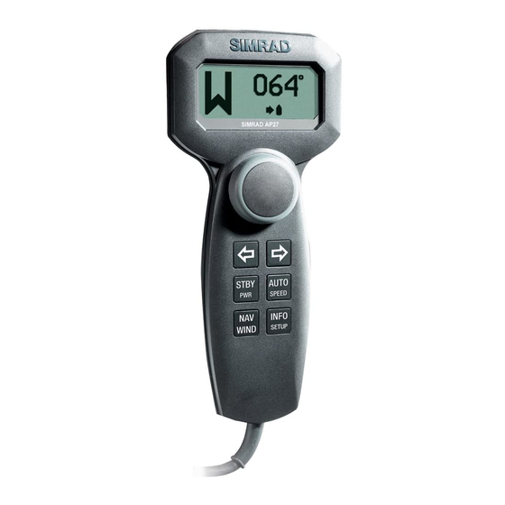
AP27 Control Unit A portable control unit with 7 m (20 ft.) of cable. It has the same autopilot functions as AP26 and can be used as a hand held autopilot or be mounted in a fixed, bracket mount. Autopilot Computer The AC05 Autopilot Computer is the heart in the autopilot system. -
Page 13: Heading Sensors
Optional equipment A series of optional equipment are available for the basic AP26 and AP27 systems. R3000X Remote Control A small handheld remote control with two push buttons for... -
Page 14: Software Record
Software record When the system is switched on, a status display shows the software versions for the control unit and the autopilot computer. See page 17. Software version Description SW 1.2.00 First Volvo IPS compatible software for AP26 and AP27. 20222147A... - Page 15 Simrad AP26 and AP27 Autopilots This page is intentionally left blank. 20222147A...
-
Page 16: Operation
• Verify at regular intervals course and position of vessel • Always switch to Standby mode and reduce speed in due time to avoid hazardous situations Overview Figure 2-1 AP26 Front Panel 20222147A... - Page 17 Simrad AP26 and AP27 Autopilots Figure 2-2 AP27 Front Panel The control units shown above can operate as a stand alone unit in an autopilot system or combined in a multistation system. In a multistation system the command can easily be transferred from one unit to another.
-
Page 18: On/Off - Standby Mode
At first time turn on see paragraph 4.1. Note ! A single press on the STBY button switches the system ON and the following status displays are shown: Simrad Autopilot model AP26 SW 1.2.00 Software version Software release HW rev. 00 Hardware revision Sn xxxxxx SimNet no. -
Page 19: Flashing Course Knob Icon
Simrad AP26 and AP27 Autopilots Alternatively, the Standby mode display can show the mode index and current heading by a long press on the TURN/DODGE/INFO button. Refer to INFO menu, page 48. A long press (2-3 sec.) on the STBY button switches the system OFF and during this time, the alarm will sound. -
Page 20: Follow-Up Steering (Fu)
Operation Follow-Up steering (FU) In the Follow-Up steering mode the course knob may be used to set rudder commands. The commanded rudder is shown as a baragraph on the display and the rudder will move to a corresponding angle and stop. Press both Use course buttons... -
Page 21: R3000X Remote Control (Nfu)
Simrad AP26 and AP27 Autopilots R3000X Remote Control (NFU) In STANDBY mode, the rudder will SIMRAD move as long as the Port or Stbd button Push button for is pressed. Port and Stbd In AUTO mode the set course will commands change 1°... - Page 22 Operation The main Auto mode display shows: − utomatic steering mode − Set course: 340 degrees − Steering parameter: LO-A − Compass reading: 340°M − Rudder angle: 00° Alternatively, the Auto mode display can show the mode index and the set course in large characters by a long press on the TURN/DODGE/INFO button.
-
Page 23: Heading Capture
Simrad AP26 and AP27 Autopilots Heading capture When in AUTO or NoDrift mode (page 35) this feature allows you to automatically cancel the turn you are in by an instant press on the AUTO or NAV (NoDrift) button. The autopilot will... -
Page 24: Manual Selection Of Hi/Lo Parameters
Operation Speed Transition to LO parameters with increasing speed: 10 Knots Transition Speed set to 9 Knots Transition to HI parameters with decreasing speed: 8 Knots Manual Selection of HI/LO Parameters Manual selection of HI/LO parameters is necessary if there is no speed input to the autopilot or if you want to override the automatic control. -
Page 25: Pattern Steering
Simrad AP26 and AP27 Autopilots 2.10 PATTERN steering The autopilot offers a number of different pattern steering features when in AUTO mode. The U-turn pattern is always available. Other turn patterns can be selected under the User Set- up menu. Refer to Turn Pattern select on page 45. -
Page 26: C-Turn
Operation C-turn The autopilot provides a continuous turn feature when in AUTO mode. This may be used for circling fish or a particular object on the seabed. C-turn makes the boat turn in a circle with a constant rate of turn. The user decides whether the C-turn should be made to Port or to Starboard. -
Page 27: Spiral-Turn
Simrad AP26 and AP27 Autopilots Spiral-turn The spiral turn feature may also be used for circling fish or when searching a particular object on the seabed. Spiral-turn makes the boat turn in a spiral with a decreasing or increasing rate of turn. The user decides whether the spiral-turn should be made to Port or Starboard. -
Page 28: Zigzag-Turns
Operation Zigzag-turns A zigzag turn pattern is also available when in AUTO mode. The user decides whether the first turn should be made to Port or Starboard. Ensure that the zigzag-turn pattern has been selected under the User Set-up menu. Refer to Turn Pattern select on page 45. To enter zigzag turn mode: Press of the TURN/DODGE/INFO button repeatedly until ZIGZAG is flashing in the display. -
Page 29: Square-Turn
Simrad AP26 and AP27 Autopilots Square-turn The square turn feature in AUTO mode can also be made a rectangle or any pattern when the next turn is 90°. The user decides whether the first turn should be to Port or Starboard. -
Page 30: Lazy S-Turn
Operation Lazy S-turn The autopilot also provides a lazy S-turn feature when in AUTO mode. The user decides whether the initial turn should be made to Port or to Starboard. Ensure that the lazy S-turn pattern has been selected under the User Set-up menu. -
Page 31: Depth Contour
Simrad AP26 and AP27 Autopilots Depth Contour Steering to a depth contour is also an AUTO mode feature. With input from an echo sounder, the autopilot can be set to steer the boat to a set depth. This is very useful if you want to follow a depth contour. - Page 32 Operation When the wanted depth is shown in the display, activate the depth contour steering with PORT or STBD button (any of the two). If you do not press PORT or STBD within 1 minute, the autopilot will return to AUTO mode and stay on course.
-
Page 33: Dodge In Auto
Simrad AP26 and AP27 Autopilots CCA set to 15 degrees Approaching reference depth from port Reference depth CCA set to 15 degrees Approaching reference depth from starboard Range: (0-50) 2.11 Dodge in AUTO Dodging is useful in situations where you need to quickly take control of the helm to steer around an obstruction, and then resume the previous set heading. -
Page 34: Thruster Steering (Optional)
Operation 2. Non Follow Up steering or using NFU by pressing: steering lever 3. Follow Up steering by and using the pressing both: course knob To return from Dodge mode, press one of the following: Selects AUTO Selects AUTO mode and mode with the returns to the current heading as... - Page 35 Simrad AP26 and AP27 Autopilots Examples of display pictures: STANDBY Non-Follow Up steering mode Heading to be Heading to be maintained by rudder maintained by rudder and thruster AUTO mode Heading maintained Heading maintained by rudder by rudder and thruster...
-
Page 36: Nodrift
Operation 2.13 NoDrift The NoDrift mode is an alternative to route steering in NAV mode, and is automatically entered when you press the NAV WIND button provided NoDrift has been selected in the (user) SETUP menu (page 42). The autopilot will steer to an imaginary waypoint and the bearing is the boat’s heading at the very moment the NoDrift mode is engaged. -
Page 37: Navigating With The Ap26 And Ap27
Simrad AP26 and AP27 Autopilots 2.14 Navigating with the AP26 and AP27 The autopilot has the capability to use steering information from an external navigator (GPS, Chart Plotter) to direct the boat to a specific waypoint location, or through a route of waypoints. In the NAV mode, the autopilot uses the compass as heading source for course keeping. - Page 38 Operation The prompt display shows the name or number of the next waypoint (WP), the bearing of the track line (BWW) from the previous waypoint to the destination waypoint, the required course change (CHG) and the direction in which the boat will turn.
-
Page 39: Setting The Waypoint Arrival Circle
Simrad AP26 and AP27 Autopilots will output an audible warning, display an alert screen with the new course information, and automatically change course onto the new leg. If the required course change is more than the NAV change limit Note ! °... -
Page 40: Dodge In Nav
Operation Example: With the speed of 20 knots you should use a waypoint circle with radius 0.09 nm. The distance between any waypoints in a route must not be Note ! smaller than the radius of the waypoint arrival circle when using automatic waypoint shift. -
Page 41: Selecting A Different Navigation Source
Simrad AP26 and AP27 Autopilots Selects NAV mode at present position with a new NAV prompt. May result in a less accurate return to the track. Selects AUTO mode with the current heading as the set course. 2.16 Selecting a different Navigation source If you have more than one navigation source connected to the autopilot, you will be able to choose any for navigation. -
Page 42: User Set-Up Menu
2-3 seconds). 2.19 User Set-up Menu In the AP26 and AP27, all modes except NFU and FU have a complemental User Set-up menu. You can easily access the set- up menu by a quick double press on the NAV/WIND/SETUP button. -
Page 43: Standby Mode
10 levels (10 = brightest). The setting is stored when the system is turned off. Adjustment is local to the control unit you adjust or synchronized with other units in the Simrad Group (page 89). NAV source Select the source for NAV mode steering e.g. CP34. - Page 44 – – indicates that no source is supplying the data available. Notes ! 1. Simrad products will be identified by the product name provided the data is available on SimNet. If speed data is provided from the Volvo IPS system to the autopilot computer, the display will read IPS.
- Page 45 Select the source for Wind Angle. Wind Calculated Select the source for Calculated Wind data for the Simrad group. The autopilot uses internal sources irrespective of the selected source. Water Speed Select the source for water speed (normally the same as the source providing Log data).
- Page 46 Operation Course Adjust When using the (PORT) or (STBD) buttons in AUTO mode, you are changing the set course in 1° increments. If you prefer the increments to be 10° each press, proceed as follows: Select Course adjust and turn the course knob to change the setting.
-
Page 47: Auto Mode
Other relevant settings are described under STANDBY mode in this chapter. Response The Autotune function in the AP26 and AP27 is so refined that 80-85 % of the boats will need no further adjustments of the steering parameters. On some boats, however, or at particular sea conditions a fine tuning of the steering parameters may improve the performance of the autopilot. -
Page 48: Nav Mode
Operation Thruster sensivity (only available if a thruster is connected). The Thruster sensitivity determines how many degrees the vessel will deviate from the set course before a thruster command is given. As the vessel deviates from its heading, the thruster will push the vessel back on. -
Page 49: Info Menu
Simrad AP26 and AP27 Autopilots 2.20 INFO menu A number of instrument pages are available under each mode screen if the required NMEA 0183 sentences are provided (see paragraph 8.1) or the information is available on SimNet (page 89). The INFO menu is accessed by a long press on the TURN/DODGE/INFO button. - Page 50 Operation Compass Heading source Heading Rudder angle Depth/Speed Depth Speed Apparent wind Apparent wind angle Apparent wind speed True wind True wind angle True wind speed True wind True wind angle VMG to wind Wind direction Wind direction Wind speed Wind shift Wind direction Wind shift...
-
Page 51: Course Knob Icon
Simrad AP26 and AP27 Autopilots Nav data Course Over Ground Speed over ground Nav data Course Over Ground Bearing Position – Waypoint Sea Temperature If you prefer not to have all the instrument pages available in the INFO menu, you may remove pages under the User setup menu. -
Page 52: Info Menu Flowchart
Operation INFO menu flowchart Long DODGE press INFO 3-5 sec. time-out Long Toggle DODGE DODGE press INFO INFO 3-5 sec. time-out 20222147A... -
Page 53: Alternative Mode Screens In Stby, Auto And Nav
Simrad AP26 and AP27 Autopilots Alternative mode screens in STBY, AUTO and NAV Main (STBY, AUTO, NAV) Alternative Long press DO DG E INFO 3-5 sec. time out INFO menu and Main screen, active unit 3-5 sec. time out Whenever the INFO menu is active and the mode index is... -
Page 54: Installation
3 INSTALLATION General This section provides detailed information required to successfully installing the AP26 and AP27 Autopilot system. A basic autopilot systems include only three modules that need to be mounted in different locations on the boat, and also need to interface with at least three different systems on the boat: •... -
Page 55: Unpacking And Handling
• AC05 Autopilot computer and one 10 m (33') Robnet2 cable. • Interconnection cable to Volvo IPS 1 m (3’) • RC36 Rate Compass with 15 m (49') cable attached. • Three autopilot manuals (use the AP26/AP27 manual) • Optional equipment that may have been ordered for the installation. -
Page 56: Autopilot System Layout
Installation Autopilot System Layout Figure 3-1 Autopilot system layout with options Autopilot computer installation The autopilot computer is designed to operate in a location with ambient temperatures below +55°C (+130°F). It must be mounted close to the Volvo Autopilot Interface within the length of the interconnection cable, 1 m (3’). -
Page 57: Cable Connections
Simrad AP26 and AP27 Autopilots Cable connections Use only shielded cables, also for the Mains input. Signal cables should be 0.5 mm (AWG20) twisted pairs. The mains supply cable should have sufficient wire gauge; minimum 1,5 mm (AWG14). Grounding and RFI The autopilot system has excellent RFI protection. -
Page 58: Cable Strain Relief
Installation Cable strain relief Once all the cables have been run to the appropriate peripherals and connected to the autopilot computer unit they should be secured to ensure that they are not snagged or exposed to excess strain. Screw the strain relief tab to the cable exit port on the autopilot computer unit using the screws supplied and secure the cables to the tab using the wraps as shown. -
Page 59: Control Unit Installation
This way of mounting is simpler, but will lift the unit from the panel surface. When installed adjacent to Simrad equipment there will be a difference in height between the autopilot and the other equipment. • Use the template and drill hole(s) only for the connectors. -
Page 60: Optional Bracket Mounting
• Connect the Robnet2 cable(s) to the control unit connector(s) (See note on page 60). Figure 3-4 AP26 Bracket mounting ROBNET2 network cables As Robnet2 units have two Robnet2 connectors (blue) they can be used as "jack points" for further expansion of the system. - Page 61 Simrad AP26 and AP27 Autopilots available in 1, 5 and 10 m length. For cable extension a Robnet2 T-Joiner is required. When installing a system, try to minimize the total cable length by connecting all Robnet2 units to the nearest available Robnet2 connector.
-
Page 62: Ap27 Connection
IPS system. The gateway kit must be ordered from Volvo under P/N 3819744. AP27 connection If a Simrad AP27 is part of the system, use the JP27 Jack Point and connect as shown on Figure 3-5 and Figure 1-2. Note ! The AP27 cable contains an air-breathing tube. - Page 63 Simrad AP26 and AP27 Autopilots The heading sensor is the most important part of the autopilot system and great care should be taken when deciding the mounting location. As the heading is displayed on the Control Unit, the heading sensor can be mounted at a remote location.
-
Page 64: R3000X Remote Control Installation
Installation RATE COMPASS AP16, AP25, AP26 Figure 3-9 RC36 connection to autopilot control unit Plug the RC36 into a Robnet2 connector (see Figure 3-5). 3.10 R3000X Remote Control installation R3000X should be mounted in the supplied bracket that can be fixed by four mounting screws. -
Page 65: Js10 Joystick
Simrad AP26 and AP27 Autopilots 3.11 JS10 Joystick Refer to separate installation instructions supplied with the JS10 Joystick. 3.12 S35 NFU Lever installation The unit is mounted to a bulkhead or panel by two screws from the front. The cable is connected to the autopilot computer according to Figure 3-11. -
Page 66: Simnet
Installation 4. The AC05 has high speed compass heading output to Simrad and Furuno radars (Clock/Data interface). The different connecting diagrams on the following pages illustrate the interface possibilities of the autopilots. 3.14 SimNet The SimNet cable system with very small plugs in both ends makes it easy to run the cables, only 10 mm (3/8”) holes are... - Page 67 Simrad AP26 and AP27 Autopilots 4. SimNet will power an IS12 instrument system. Hence SimNet on other equipment can be connected and powered via IS12. 5. SimNet must be properly terminated. The SimNet network has to be terminated according to the number and type of products connected.
- Page 68 Installation DATA COM BI COM BI COM BI SIM RAD IS12 SIM RA D IS1 2 SIM RAD IS12 SIM RA D IS1 2 ALARM UPPER LOWER ALARM UPPER LOWER ALARM UPPER LOWER UPPER LOWER LIGHT LIGHT LIGHT LIGHT PAGE TIMER INFO INFO...
- Page 69 Simrad AP26 and AP27 Autopilots Figure 3-15 Robnet2 and SimNet network * The wind transducer has a built in terminator 20222147A...
- Page 70 Installation Figure 3-16 Robnet2, SimNet and Roblink network Notes ! 1. Maximum total length of SimNet cable is 60 m (196 ft.) excluding the 30 m (99 ft.) of masthead cable. 2. It is not necessary to connect all autopilot control units to SimNet for data sharing.
-
Page 71: Radar Clock/Data Heading Output
Simrad AP26 and AP27 Autopilots 3.15 Radar Clock/Data Heading Output SIMRAD/ANRITSU AUTOPILOT COMPUTER FURUNO RADAR T B 4 R A D A R Figure 3-17 Radar Clock/Data connection 3.16 IS15 Instrument installation For installation and operation of the IS15 instruments refer to separate manuals. -
Page 72: Configuration And Setup
Configuration and Setup 4 CONFIGURATION AND SETUP First time turn on Before attempting to turn on the autopilot and perform an Installation Setup, the hardware installation and electrical connections must be completed in accordance with the installation instructions. The design of the autopilot includes advanced features that have simplified the installation and setup of an autopilot. -
Page 73: Description Of Installation Settings
Simrad AP26 and AP27 Autopilots Description of Installation Settings Note ! The installation settings must be performed as part of the installation of the autopilot system. Failure to do so correctly may prohibit the autopilot from functioning properly! The Installation menu can only be accessed in STBY mode. -
Page 74: Installation Menu
Configuration and Setup • The Installation Settings are global except for display units and language, enabling settings to be distributed to all control units in the system. Installation Menu Installation Menu presented autopilot display by pressing and holding the NAV/WIND/SETUP button for 5 seconds. - Page 75 Simrad AP26 and AP27 Autopilots ENTER INSTALLATION MENU INSTALLATION SYMBOLS BY PRESSING AND HOLDING THE MENU NAV BUTTON FOR 5 SECONDS SELECT OR CONFIRM BY COURSE KNOB LANGUAGE MENU PROCEED TO NEXT MENU ITEM LANGUAGE ENGLISH BY PRESSING STBD BUTTON...
-
Page 76: Language Selection
Configuration and Setup Language selection To access the language selection in the Installation Menu, confirm “Yes” by turning the course knob clockwise The autopilot can present the display text in eight different languages: English, Deutsch, Francais, Espanol, Italiano, Nederlands, Svenska and Norsk. Turn the course knob to select the language you wish to use. -
Page 77: Sea Trial
Simrad AP26 and AP27 Autopilots Use the STBD button to select an item and the course knob to select the unit. Available units are: Wind Speed: Knots (kt) or meter/second (m/s) Sea temperature: Fahrenheit (°F) or Celsius (°C) Depth: Meter (m) or feet (ft) -
Page 78: Compass Calibration
Compass calibration This function will activate the compass calibration procedure for Simrad compasses connected to Robnet2 and the Autopilot Computer terminals (HS). Notes ! The RC36 Rate Compass that comes with the autopilot as standard will store the calibration and off-set data in its own memory. - Page 79 Simrad AP26 and AP27 Autopilots 4. When the calibration is completed, (after having made approximately 1 1/4 turns), it will be confirmed by the display reading “Confirmed”. Compass deviation The heading from a magnetic heading sensor will normally have a deviation when compared with the actual direction of the earth’s magnetic field.
-
Page 80: Compass Offset
Configuration and Setup Compass Offset After calibration, also check the compass readout against a known reference, a compensated compass or a bearing. If the reading has a fixed offset, proceed to next menu item by pressing STBD button or return to STANDBY mode by pressing the STBY button. -
Page 81: Set Thrust Direction
Simrad AP26 and AP27 Autopilots Set Thrust Direction (Only applicable if a thruster is connected) Rotate the course knob clockwise to activate the Set thrust direction setting. Rotate the course knob CW and verify that the vessel turns to starboard. The thruster stops after 10 seconds, or when the STBD button is pressed. -
Page 82: Depth Offset
Configuration and Setup The inputs to the AWF are heading, boat speed, apparent wind angle and wind speed. Verify that these inputs are available in User Setup/Source Select. The boat speed input to the AWF is Speed Over Ground (SOG) or speed through water. -
Page 83: Transition Speed
Simrad AP26 and AP27 Autopilots Recommended speed during Automatic tuning varies with the type of boat, but should not exceed 10 knots (6-8 knots is recommended). It should be performed in calm or moderate sea conditions. Note ! Automatic tuning should not be performed at planing speed or in... -
Page 84: Init Nav
Configuration and Setup It is recommended that you set the transition speed to a speed that represents the speed where the hull begins to plane, or the speed where you change from slow to cruising speed. The speed used for the automatic transition is obtained with the following priority: 1. -
Page 85: Nav Change Limit
Simrad AP26 and AP27 Autopilots NAV change limit In NAV mode, when the required course change at the approaching waypoint is bigger than the set limit, you are prompt to verify that the upcoming course change is acceptable. The limit can be set to 10°, 20°... -
Page 86: Manual Parameter Adjust
Configuration and Setup Manual parameter adjust Use course knob to Displayed Automatic Default Manual adjust parameters parameter tuning Rudder LO 0.20 Cont.Rudder LO 1.00 Autotrim LO 40 sec. HIgh Use PORT and Rudder HI 0.30 STBD buttons to Cont.Rudder HI 1.40 step through parameters... -
Page 87: Recall Autotuned
Simrad AP26 and AP27 Autopilots Counter Rudder is the parameter that counteracts the effect of the boats turn rate and inertia. For a short time period it is superimposed on the proportional rudder response as provided by the heading error. It may sometimes appear as if it tends to make the rudder move to the wrong side (counter rudder). -
Page 88: Service Menu
Configuration and Setup Exit the Parameter menu by pressing STBD button to proceed to the Service menu, or press STBY to return to normal autopilot operation. Service Menu Select STANDBY mode and then enter the Installation Menu by pressing and holding the NAV/WIND/SETUP button for 5 seconds. -
Page 89: Simnet Data Screen
Simrad AP26 and AP27 Autopilots SimNet Data Screen Select the screen by pressing the STBD button and confirm by rotating the course knob clockwise. Step through the menu by pressing the STBD button. The menu provides you with status information about the different SimNet messages used by the system. -
Page 90: Simnet Setup
Sn 00000 is the unique SimNet ID number for the specific autopilot control unit. Group selection SIMRAD: Autopilot is part of the Simrad Group. Source selection will be common for the products in the group (synchronized). STAND ALONE: Source... -
Page 91: Master Reset
Simrad AP26 and AP27 Autopilots Instance number An item to identify units by a number when the autopilot is connected to a NMEA2000 Network. On SimNet units the Instance number is added to the product name e.g. AP26-1, AP26-2 for easy identification on various display screens. -
Page 92: Final Sea Trial
Configuration and Setup clockwise. The display will then read: “Master Reset confirmed”. Unless you have made a Master Reset, exit the Installation Menu by pressing STBY to return to normal autopilot operation. In the event a Master Reset has been made, refer to chapter 4.2. Final sea trial After having completed all settings in the Installation Menu, take the boat out and perform a final sea trial in open waters at a safe... - Page 93 Simrad AP26 and AP27 Autopilots • Changing modes. Explain briefly what takes place in the different modes. • Regaining manual control from any mode. Point out in what modes the helm is engaged by the autopilot and vice versa, see page 18.
-
Page 94: Maintenance
Maintenance 5 MAINTENANCE Control unit The AP26 and AP27 Control Units will under normal use require little maintenance. If the unit requires any form of cleaning, use fresh water and a mild soap solution (not a detergent). It is important to avoid using chemical cleaners and hydrocarbons such as diesel, petrol etc. -
Page 95: Autopilot Computer
Simrad AP26 and AP27 Autopilots Autopilot Computer Remove the bottom cover to get access to the software download connector. Software download connector Figure 5-1 Part of AC05 PCB Autopilot Control Unit Software download connector Figure 5-2 Part of AP26 PCB 20222147A... - Page 96 Maintenance Software download connector Figure 5-3 Part of AP27 PCB Remove the cables and unscrew the screws that secure the back cover. Apply a firm pull with your fingers to pull the back cover loose from the connector pins. Then you have access to the software download connector.
- Page 97 Simrad AP26 and AP27 Autopilots This page is intentionally left blank. 20222147A...
-
Page 98: Trouble Shooting
Refer to the table below for hints and try to solve the problem yourself. You may also consult your nearest Simrad dealer for assistance, if required. Perform any repair action in the listed sequence. – – – in a display indicates that data is missing. - Page 99 Simrad AP26 and AP27 Autopilots Display readout Probable fault Recommended action Shallow water The depth is inside 1. Carefully observe the actual the set limit or outside depth. (Only if AP25 is the range. part of the 2. Adjust the alarm limit if not system) Depth data is missing.
- Page 100 Trouble shooting Display readout Probable fault Recommended action ACXX high Excessive Switch off autopilot temp. temperature inside Autopilot Computer Memory failure Wrong checksum Perform a "Master reset". Switch off ACXX on memory and on again. If the alarm is repeated, parameters or replace Autopilot Computer PCB.
-
Page 101: Spare Parts List
Simrad AP26 and AP27 Autopilots 7 SPARE PARTS LIST AP26 Control Unit 22087910 AP26 Control Unit 22088439 AP26 mounting kit consisting of: 22084529 Cabinet corners 22085807 Gasket 44165181 Screw 3.5x19 44165645 Screw 3.5x32 22085872 Optional mounting bracket consisting of: 44148906 Screw M4x12... - Page 102 Spare Parts List 22089247 AC05 Bushing 44152056 Screw M3x8 44152155 Screw M3x16 44142552 Screw M5x20 44120681 Plug-in Terminal 4-way 44133601 Plug-in Terminal 5-way 44135333 Plug-in Terminal 2-way 22089304 AC05 Software RC36 Rate compass 22086920 RC36 Rate Compass 22081442 Installation Accessories Consisting of: 20104972 Mounting plate (2) 44140762 Screw 3.5x25 (2) 44140770 Screw 30x9 (4)
- Page 103 Simrad AP26 and AP27 Autopilots 24005902 SimNet power w/termination 2 m (6.6’) 24005910 SimNet power w/o termination 2 m (6.6’) 24005936 AT10 Universal NMEA0183 converter 24005944 AT15 Active Tee w/connector, IS15 24005928 SimNet cable protection cap 24005729 SimNet cable to Micro-C. Adapter (drop) cable for SimNet products in a NMEA2000 network.
-
Page 104: Technical Specifications
Sea state control:....Adaptive sea state filter or manual Language selection: ....English, Norwegian, French, Spanish, German, Italian, Dutch, Swedish. Electronic Interface: Navigation interface:..Standard (NMEA 0183) Compass heading output: . Simrad and Furuno radar display (clock/data) NMEA2000 interface..Via SimNet port and SimNet/NMEA2000 adapter cable 20222147A... -
Page 105: Ap26 Control Unit
Simrad AP26 and AP27 Autopilots Heading sensors: Standard: ......RC36 Rate Compass Course Selection:....... Rotary course dial and push button Alarms: ........Audible and visual, optional external Alarm modes: ......Off course, system failures, overload Steering modes: ......Standby, Non-follow up, Follow-up, Auto, Nav Special Turn modes: .... - Page 106 Safe distance to compass: ..0.3 m (1.0 ft.) Temperature: Operating: ......0 to +55 °C (+32 to +130 °F) Storage: ......–30 to +80 °C (–22 to +176 °F) Figure 8-1 AP26 Control Unit – dimensions (Mounting bracket is optional equipment) 20222147A...
-
Page 107: Ap27 Control Unit
Simrad AP26 and AP27 Autopilots AP27 Control Unit Dimensions: ....... See Figure 8-2 Weight: ........0,57 kg (1,25 lbs) Power consumption ....3 W Display: Type: ......... Backlit LCD matrix display Resolution: ......80 x 32 pixels Color: ......... Black Illumination: ...... -
Page 108: Ac05 Autopilot Computer
Technical Specifications AC05 Autopilot Computer Dimensions: ....... See Figure 8-3 Weight: ........1,1 kg (2,4 lbs) Supply voltage:......10.8 - 31.2 VDC Reverse voltage protection ..Yes Environmental Protection:..IP22 Safe distance to compass: ..1.0 m (3 ft.) Power consumption: ....5 Watt (electronics) External Alarm: ...... -
Page 109: Rc36 Rate Compass
Simrad AP26 and AP27 Autopilots RC36 Rate compass Dimensions: ....... See Figure 8-4 Weight: ........0,9 kg (2,0 lbs) Supply and interface:....Robnet2 Power consumption: ....0,9 watts Automatic Performance: Calibration: ....... Automatically activated by control head Gain compensation: ..Automatically adjusted continuously Rate sensor stabilized heading output Accuracy:........ -
Page 110: R3000X Remote Control
Technical Specifications R3000X Remote Control Dimensions: ......See Figure 8-5 Weight:........0,4 kg (0,9 lbs) Material:.....Epoxy coated aluminum Protection ..........IP56 Safe distance to compass: ..0.15 m (0.5 ft.) Temperature range: Operation: ..–25 to +55 °C (–13 to +130 °F) Storage: .. -
Page 111: Simnet
Simrad AP26 and AP27 Autopilots SimNet Maximum number of products connected in a network:........50 Maximum cable length: ..............120 m (400’) Bit rate of the bus: .................250 Kbit/second Maximum DC current through a single SimNet plug ......... 5A SimNet power supply: .... -
Page 112: Ip Protection
Technical Specifications IP protection Each part of a Simrad autopilot system has a two digits IP protection code. The IP rating is a method to classify the degree of protection against solid objects, water ingress and impact afforded by electrical equipment and enclosures. The system is recognized in most European countries and is set out in a number of British and European standards. -
Page 113: Simnet Messages
Simrad AP26 and AP27 Autopilots 8.10 SimNet messages SimNet/NMEA2000 messages and data overview Message ident. Data source: N=nav, P=pos, H=heading, D=depth, Wa=Wind apparent, P P P P P P Wt=Wind True, WaS=Water Speed/ WaT=Water temp, Dl=Distance log, C=Calculated) Compass Data... - Page 114 Technical Specifications Remarks: Indata use * SimNet proprietary x In INFO views Depth+Offset is displayed if x offset is present *Only transmitted if NMEA183/RC36/RFC35 is source x* x* x* 20222147A...
- Page 115 Simrad AP26 and AP27 Autopilots This page is intentionally left blank. 20222147A...
-
Page 116: Glossary
Glossary 9 GLOSSARY Apparent wind – The speed and direction from which the wind appears to blow with reference to the bow when the boat is moving (also called relative wind). Arrival alarm – An alarm signal issued by a GPS/chartplotter that indicates arrival at or at a predetermined distance from a waypoint. - Page 117 SimNet controller. When connected to SimNet they will automatically pick the first available source on SimNet and lock on to that. When a Class 1 product is added to the Simrad Group, Class 2 products will automatically subordinate themselves to the Class 1 source selection.
- Page 118 Glossary True bearing – Bearing relative to true north; compass bearing corrected for compass error. True heading – Heading relative to true north (the meridian). Waypoint - A discrete point, stored in a navigator, located on the surface of the earth. Normally this point will be identified by Lat/Lon coordinates although in some systems it may be shown by T.D.'s.
-
Page 119: Index
Simrad AP26 and AP27 Autopilots 10 INDEX alarm depth offset, 81 external, 70 depth source, 44 listing, 97 depth-turn, 30, 45 apparent wind, 115 display units, 75 arrival circle, 38 Dodging, 32 auto setup, 71 automatic tuning, 81 autopilot computer... - Page 120 SimNet backlight, 89 master reset, 90 SimNet gateway, 90 modes of operation SimNet reset, 90 auto, 20 SimNet setup, 89 NoDrift, 35 Simrad group, 89 standby, 17 software program exchange, turn, 24 mounting software setup, 71 bracket, 59 panel, 58...
- Page 121 Simrad AP26 and AP27 Autopilots water temperature source, 44 wind damping, 80 wind offset, 80 wind angle source, 44 zigzag-turn, 27, 45 wind calculated source, 44 20222147A...