
Related Manuals for Simrad AP24


Summary of Contents for Simrad AP24
- Page 1 Installation manual Simrad AP24/28 – EVC, Volvo IPS Pilot System with SG05 SimNet-Volvo Gateway English www.simrad-yachting.com A brand by Navico - Leader in Marine Electronics...
- Page 2 I n st a lla t ion m a n u a l Sim rad AP24/ 28 – EVC, Volvo I PS Pilot Syst em wit h SG05 Sim Net - Volvo Gat eway English Docum ent no: 20223210 Revision:...
- Page 3 Abou t t h is m a n u a l Rev. A 08.05.08 First issue This m anual is int ended as a reference guide for inst alling and m aint aining a Sim rad aut opilot syst em wit h t he Sim rad SG05 Sim Net - Volvo Gat eway for Elect ronic Vessel Cont rol.
-
Page 4: Table Of Contents
2.4 Aut opilot syst em layout ......9 2.5 SG05 Gat eway inst allat ion ....... 10 2.6 AP24 and AP28 Cont rol unit inst allat ion ..11 2.7 RC42 Com pass inst allat ion ...... 13 2.8 I nt erfacing ..........14 2.9 Sim Net .......... - Page 5 4.8 I P prot ect ion ......... 30 4 | SG05 I nst allat ion m anual...
-
Page 6: Syst E M De Scr Ipt Ion
1 Syst e m de scr ipt ion 1 .1 Ge n e r a l The Sim rad SG05 is a gat eway for int erfacing t he AP24 and AP28 aut opilot syst em s t o Volvo Pent a Elect ronic Vessel Cont rol ( EVC) . -
Page 7: Soft Ware Record
1 .3 Soft w a r e r e cor d Con t r ol unit s When t he syst em is swit ched on, a st at us display shows t he serial num ber and soft ware version for t he cont rol unit . -
Page 8: Nst A Lla T Ion
2 I n st a lla t ion An aut opilot syst em includes several unit s t hat need t o be m ount ed in different locat ions on t he boat , and also need t o connect wit h at least t hree different syst em s on t he boat : •... -
Page 9: Det Erm Ine Syst Em Configurat Ion
An aut opilot syst em will include: • Cont rol unit ( AP24 or AP28) wit h accessories • SG05 Gat ew ay wit h accessories • Com pass ( RC42) wit h 5,5 m ( 18') Sim Net cable at t ached •... -
Page 10: Aut Opilot Syst Em Layout
2 .4 Au t opilot syst e m la you t AP24 AP28 Control Unit Control Unit TURN WIND MODE TURN AUTO STBY DRIFT MENU AUTO STB Y MENU SG05 Gateway 12V SimNet supply (SimNet cable with termination) RC42 Rate Compass... -
Page 11: Sg05 Gat Eway Inst Allat Ion
SG05 has a built in LED t hat will alt ernat e wit h 1 Hz when t he unit is up running. Figur e 2- 3 SG05 m ount ing Autopilot Interface kit (Volvo Penta part number 3819744) Simrad SG05 Gateway Autopilot Gateway EVC connect point Y-split... -
Page 12: Ap24 And Ap28 Cont Rol Unit Inst Allat Ion
Apply t he front panel corners. D o n ot ove r - t igh t e n t h e m ou n t in g scr e w s! Figur e 2- 5 AP24 Panel m ount ing Operat ion | 11... - Page 13 Opt ion a l br a ck e t m ou n t in g Figur e 2- 6 AP24 Bracket m ount ing Figur e 2- 7 AP28 Panel m ount ing 12 | Operat ion...
-
Page 14: Rc42 Com Pass Inst Allat Ion
Figur e 2- 8 AP28 Bracket m ount ing 2 .7 RC4 2 Com pa ss in st a lla t ion Figur e 2- 9 Mount ing The heading sensor is t he m ost im port ant part of t he aut opilot syst em and great care should be t aken when deciding t he m ount ing locat ion. -
Page 15: I Nt Erfacing
I f t he connect ed product s have no offset feat ure, t he com pass m ust be deck or bulkhead m ount ed at hwart ship wit h t he cable gland point ing back. Select a locat ion t hat provides a solid m ount ing place free from vibrat ion, and as close t o t he vessel's cent re of roll and pit ch as possible, i.e. -
Page 16: Sim Net
2 .9 Sim N e t The Sim Net cable syst em wit h very sm all plugs in bot h ends m akes it easy t o run t he cables, only 10 m m ( 3/ 8” ) holes are required t hrough panels and bulkheads. - Page 17 For addit ional inform at ion about Sim Net ask for t he separat e Sim Net Manual. Figur e 2- 10 Sim Net Power connect ion Wind IS20 IS20 NX45 NavStation AP24 transducer * Control Unit Instrument Instrument TURN MODE...
- Page 18 AP28 AP24 IS20 IS20 Wind GS10 NX45 NavStation transducer * Control Unit Control Unit Instrument Instrument TURN WIND MODE TURN AUTO STBY DRIFT MENU AUTO STB Y MENU AT45 RC42 RS82 WR20 RS82 Black box SIMRAD RS82 WR20 12V SimNet supply...
- Page 19 Bla n k pa ge 18 | Operat ion...
- Page 20 3 Spa r e pa r t s AP2 4 Con t r ol Un it 22096614 AP24 Cont rol Unit 22096630 Mount ing kit consist ing of: 22095483 Cabinet corners ( 6) 44165181 Screw 3,5x19 ( 4) 24006355 Sim Net blocking plug...
-
Page 21: Spa R E Pa R T
Sim N e t ca ble s a n d a cce ssor ie s 24005829 Sim Net cable 0.3 m ( 1’) 24005837 Sim Net cable 2 m ( 6.6’) 24005845 Sim Net cable 5 m ( 16.6’) 24005852 Sim Net cable 10 m ( 33’) 24006363 Sim Net cable, 5.5 m ( 18’) wit h one plug... -
Page 22: Te Chnica L Spe Cifica T Ions
4 Te ch n ica l spe cifica t ion s 4 .1 Au t opilot Syst e m Boat size and t ype: Up t o 50 feet , Displacem ent , Out board, Planing St eering syst em t ypes: ........Volvo Pent a EVC I nt er - unit connect ion: ........ - Page 23 I nst r um ent dat a page int erface: I n st r u m e n t scr e e n Sim N e t / N M EA2 0 0 0 PGN * Heading PGN127250, PGN130577 Rudder angle PGN127245 Speed PGN128259, PGN129026, PGN130577...
-
Page 24: Ap24 Cont Rol Unit
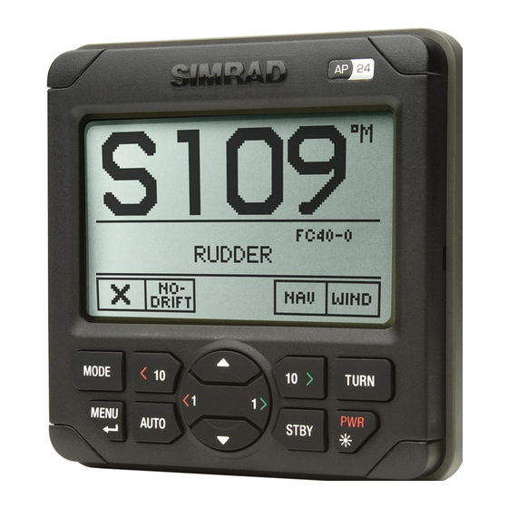
Operat ing: ......0 t o + 55 ° C ( + 32 t o + 130 ° F) St orage: ......–30 t o + 70 ° C ( –22 t o + 158 ° F) Figur e 4- 1 AP24 Cont rol Unit – dim ensions ( Mount ing bracket is opt ional equipm ent ) -
Page 25: Ap28 Cont Rol Unit
4 .3 AP2 8 Con t r ol Un it Dim ensions: ............. See Figure 4- 2 Weight : ............0,5 kg ( 1.1 lbs) Mat er ial: ... Front : Black ABS+ PC, Back : Dark gray ABS+ GF Supply and int erface: ........ -
Page 26: Sg05 Gat Eway
4 .4 SG0 5 Ga t e w a y Dim ensions: ............. See Figure 4- 3 Weight : ............0,1 kg ( 0,2 lbs) Mat er ial: ..............Polyam ide Environm ent al Prot ect ion: ..........I P44 Supply and int erface: ........ -
Page 27: Rc42 Rat E Com Pass
4 .5 RC4 2 Ra t e Com pa ss Dim ensions: ............. See Figure 4- 4 Weight : ............0,9 kg ( 2,0 lbs) Mat er ial: ............Off- whit e ABS Environm ent al Prot ect ion: ..........I P56 Tem perat ure r ange: Operat ion: ....... -
Page 28: At10 Sim Net / Nmea0183 Convert Er
Figur e 4- 4 RC42 Rat e Com pass – Dim ensions 4 .6 AT1 0 Sim N e t / N M EA0 1 8 3 con ve r t e r Technical specificat ions | 27... - Page 29 Dat a convert ed from Sim Net / NMEA2000 t o NMEA0183 ( TX) and vice versa ( RX) . N M EA0 1 8 3 se n t e n ce TX ( m a x r a t e [ H z ] ) MWV Relat ive Wind MWV True Wind 3.33...
-
Page 30: Sim Net
4 .7 Sim N e t Maxim um num ber of product s connect ed in a net work : ..50 Maxim um cable lengt h: ........150 m ( 500’) Bit rat e of t he bus: .......... 250 Kbit / second Maxim um DC current t hrough a single Sim Net plug .... - Page 31 4 .8 I P pr ot e ct ion Each par t of a Sim rad aut opilot syst em has a t wo digit s I P prot ect ion code. The I P rat ing is a m et hod t o classify t he degr ee of prot ect ion against solid obj ect s, wat er ingress and im pact afforded by elect r ical equipm ent and enclosures.