
Related Manuals for Pioneer PDP-R03U


Summary of Contents for Pioneer PDP-R03U
- Page 1 Product Training Guide Media Receiver PDP-R03U Multimedia & Web Training Department 545 Nolan Drive Suite 100 Southlake, Texas 76092...
-
Page 2: Table Of Contents
Contents Overview…………………………21 Preface ……………………….……..3 PCB Layout……………………………22 Basic Operation ………………,4-20 PC I/F Unit…………………………..23 Connecting the System.……………4 Power Supply……………………..24 Controls & Connectors………..……5 Extension Cables………………..…..25 Remote………………………..……….6 AV Unit (Basic Signal Path)………..26-27 Power On………………………………7 CC & V-Chip (Basic Signal Path)….28-29 Auto Installation…………………..….8 PC I/F (Basic Signal Path)……….…30-31 Basic Adjustment Settings……..…..9-10 Basic Audio Signal Path…………...32-33 Connections…………………………..11... -
Page 3: Preface
Safety information harm. (California Health and Safety Code Section 25249.5). Important safety data for this Pioneer model is contained in the service manual. Before returning the unit to the customer, complete all product safety obligations and tests. -
Page 4: Connecting The System
Connecting the system Connecting the system cable and the power cord to the Plasma Display Plasma Display (rear view) For details on optional PIONEER speaker (bottom view) installation refer to the speaker instruction manual provided. (WHITE) (GRAY) Power cord System cable •... -
Page 5: Controls & Connectors
INPUT 4 terminal (VIDEO) PC INPUT terminal (ANALOG RGB) CLEAR* Push CLEAR lightly with the tip of a pointed object like a ballpoint pen. PDP-R03U MEDIA RECEIVER STANDBY/ON POWER PC INPUT terminal (AUDIO) INPUT 4 terminals (AUDIO) INPUT 4 terminal (S-VIDEO) POWER button * If you’re having problems operating the Media Receiver and want to return to normal screen, even when it... -
Page 6: Remote
Remote control unit TV a: Switch the Plasma Display power on or off. FRONT SURR: Set SRS and FOCUS Sound System. Mode switch AV SELECTION: Select an audio or video setting. (AV mode: STANDARD, DYNAMIC, MOVIE, GAME, USER. /SAT PC mode: STANDARD, USER.) /DTV INPUT SCREEN MODE: Select the screen size. -
Page 7: Power On
STANDBY/ON on the Plasma Display to turn the System on. First time turning on Media Receiver Media Receiver Press POWER on the Media Receiver. MEDIA RECEIVER PDP-R03U PUSH STANDBY/ON • The power indicator on the Media Receiver lights up PLASMA DISPLAY SYSTEM POWER red. - Page 8 Initial auto installation When you turn on the Plasma Display System for the first time, it will automatically memorize the broadcasting channels where you live. Perform the following steps before you press TV a. 1. Insert the batteries into the remote control unit. 2.
-
Page 9: Auto Installation
Basic adjustment settings AV mode menu items List of AV menu items to help you with operations. MENU Description Power Control Save power by decreasing picture Energy Save [Standard] Energy Save brightness. No Signal off [Disable] System automatically shuts down if No Operation off [Disable] No Signal off... - Page 10 Basic adjustment settings PC mode menu items List of PC menu items to help you with operations. MENU Description Power Control Energy Save [Standard] Save power by decreasing picture Energy Save brightness. Power Management [Off] System automatically shuts down if RETURN Power you set the time.
-
Page 11: Connections
S-VIDEO VIDEO R-AUDIO-L S-VIDEO VIDEO R-AUDIO-L S-VIDEO S-VIDEO AV Receiver (Built-in Tuner Amp) Media Receiver PDP-R03U MEDIA RECEIVER (front view) STANDBY/ON POWER PC-AUDIO Game console/ Computer Camcorder S-VIDEO ANALOG RGB • To protect all equipment, always turn off the Media Receiver before connecting to a DVD player, VCR, Digital tuner, computer, game console, camcorder or other external equipment. -
Page 12: V-Chip Settings
Useful adjustment settings Parental control (setting V-CHIP level) V-CHIP is an electronic filtering device built into your System. This tool gives parents a great degree of control over broadcasts accessed by their children. It allows parents to select programs judged suitable for child viewing while blocking ones judged not suitable. - Page 13 Useful adjustment settings Voluntary movie rating system (MPAA) Press MENU. /SAT MENU /DTV Press a/b to select “Setup”, and then press SET/ INPUT Setup FRONT ENTER. Secret No. – – – – SURR • Secret number setting menu displays only when SELECTION “Secret No.”...
- Page 14 Useful adjustment settings Secret number setting for parental MENU control (AV mode only) /SAT Setup /DTV Allows you to use a secret number to protect certain Parental CTRL INPUT settings from being accidentally changed. FRONT Secret No. SURR Secret No. SELECTION Setting a secret number Clear Secret No.
- Page 15 Useful adjustment settings Clearing the secret number Secret number setting menu Allows you to clear your secret number. /SAT /DTV Press MENU. MENU INPUT FRONT Setup Press a/b to select “Setup”, and then press SET/ SURR Secret No. – – – – ENTER.
- Page 16 Useful adjustment settings How to temporarily release the V-CHIP BLOCK /SAT /DTV • The V-CHIP BLOCK is working and censors a INPUT FRONT broadcast, “V-CHIP HAS BEEN ACTIVATED.” SURR displays. SELECTION SPLIT SELECT Press SET/ENTER while the V-CHIP is working and SCREEN SUB CH then the secret number.
-
Page 17: Multiscreen Functions
Useful features Multiscreen functions Allows you to display two pictures on the screen at one time. Dual screen You can display two same-sized pictures except when inputting from a PC INPUT terminal. /SAT /DTV INPUT Press SPLIT. FRONT SURR • Dual screen displays and a selected input source SELECTION image displays. -
Page 18: Consumer Troubleshooting
Appendix Troubleshooting Problem Possible Solution • No power. • Make sure the Plasma Display and the Media Receiver are connected correctly. • Check if you pressed TV a on the remote control unit. If the indicator on the Plasma Display lights up red, press TV a. •... -
Page 19: Pc Compatibility Chart
Computer compatibility chart Frequency Resolution Remarks 640 400 85 Hz 720 400 70 Hz 85 Hz 640 480 60 Hz Macintosh 13 (67 Hz) 65 Hz 72 Hz 75 Hz 85 Hz 800 600 56 Hz 60 Hz 72 Hz 75 Hz 85 Hz Macintosh 16... -
Page 20: Factory Preset
HOW TO SET THE FACTORY PRESETTINGS Press and hold down CLEAR on the Media Receiver while it is in standby mode. Then press STANDBY/ON on the Plasma Display or TV a on the remote control unit to turn the Plasma Display System on. All setting items (except TV channel) return to the factory presetting. -
Page 21: Overview
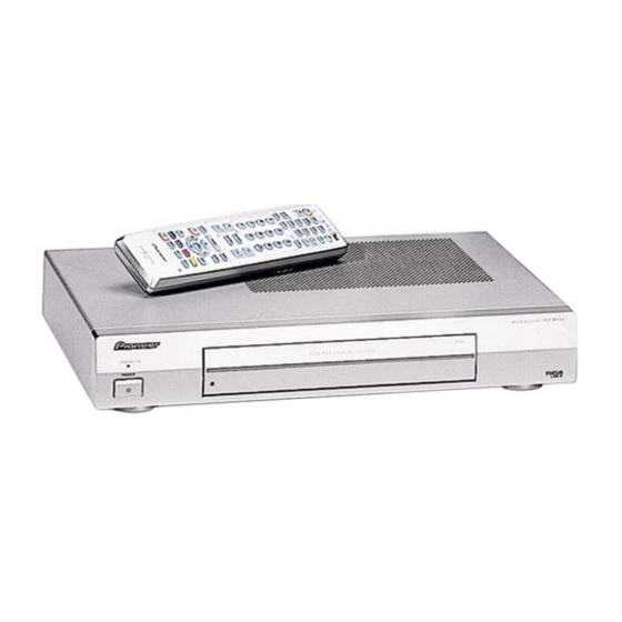
PDP-R03U Overview The Pioneer PDP-R03U Media Receiver is designed for use with Plasma Display Models PDP503PU or PDP433PU. The units must be connected using the two system cables for proper operation. The Media receiver cannot operate as a stand-alone unit. The Digital Video output from the... -
Page 22: Pcb Layout
PDP-R03U PCB Layout Power Unit PC I/F Unit Unit Front Unit Tuner (B) Main Unit Tuner (A) -
Page 23: Pc/If Unit
PC/IF Unit Connector RS-232C Service... -
Page 24: Power Supply
Power Supply Unit... -
Page 25: Extension Cables
Service Extension Cables... - Page 26 AV Unit (Basic Video Signal Path) Input IC803 IC1301 IC801 RGB Matrix IC7001 Tuner Inputs (2) Color Decoder Select 3-D Y/C Y/C in Y/CB/CR in Video/YC Inputs (4) Y/CB/CR out RGB out Unit Y/CB/CR Closed Caption IC1401 Decoder RGB (1) IC1602 Comp Select...
- Page 27 AV Unit (Basic Video Signal Path) Overview The Media Receiver can accept 2 tuner inputs, 4 video or YC inputs, 1 RGB input, 2 component inputs and 1 PC input. IC1301 selects tuner or YC inputs. IC1401 selects RGB or component inputs. The media receiver has a 50/50 split screen feature referred to in this diagram as main picture and sub-picture.
-
Page 28: Cc & V-Chip (Basic Signal Path)
Closed Caption & V-Chip (Basic Signal Path) IC803 IC1301 Tuner Input 1 IC801 RGB Matrix IC7001 Color Decoder Select 3-D Y/C Y/C in Y/CB/CR in Tuner Input 2 Y/CB/CR out RGB out Unit V-Chip Switch Main IC2504 IC1603 Closed Caption Comp Decoder Select... - Page 29 Closed Caption & V-Chip (Basic Signal Path) Overview The Media Receiver incorporates one Closed Caption Decoder and two V-Chip Program Blocking IC’s. The two V-Chip Decoders are for main and sub-picture. The Closed Caption Decoder is used for the main picture only. 31K Component signals do not pass through either of these circuits.
-
Page 30: Pc I/F (Basic Signal Path)
PC I/F (Basic Signal Path) Parallel Outputs PC I/F Board A/V Unit 2 Phase 6x8=64 Bit Parallel Outputs Input 3x8=24 Bit 8 Bit R_A TMDS 80 mhz (4) Channel IC810 8 Bit R_B 800 mhz IC803 6.7mhz Serial 2 Phase 8 Bit G_A CVIC RGB Matrix... - Page 31 PC I/F (Basic Signal Path) Overview The PC I/F board main functions are to take the main, sub-picture and PC inputs from the A/V unit and analog to digital convert each signal, perform I/P conversion, add on screen display information and output the picture data to the plasma display as a DVI signal with content protection.
-
Page 32: Basic Audio Signal Path
AV Unit (Basic Audio Signal Path) Output to Plasma IC2501 Tuner Input 1 (System Cable) Sound Processor Tuner Input 2 Monitor output Main Audio L/R Sub Audio L/R Audio Input 1 IC1301 Audio Input 2 Audio Input 3 Select Audio Input 4 PC Audio Input... -
Page 33: Basic Audio Signal Path
AV Unit (Basic Audio Signal Path) All Audio inputs enter IC1301 the AV selector switch except Tuner 1 and 2 audio IF signals. IC2501 has a built in TV audio IF demodulator for the two tuner inputs. The selector IC1301 separates the right and left channel selected outputs for main and sub-audio. -
Page 34: Power On Procedure
Power On Procedure Pioneer Plasma PDP503PU or PDP-433PU DIgital Video Assembly Media Receiver Interface PCB Module CPU HDCP TMDS Key IC Receiver SCL Pin 6 Power SDA Pin 7 DVI Connector System Connector TMDS Power supply Main CPU IC413 DC TO DC... - Page 35 Power On Procedure With both the media receiver and plasma units plugged in and the main power switch on, pressing the Power on/ Standby switch on the remote or on the plasma display will start the following power up sequence. When the standby key is pressed the plasma display outputs +5v to the media receiver on the SM Power line.
-
Page 36: Dc To Dc Converter Startup
DC to DC Converter Startup +2.5v +3.3v Main Power Supply Main Unit 10 volt supply to DC to DC Converter AC In +35v Always on backup 5 volts -12v DC to DC Relay Driver Converter Q705 +5v CCKM 5 volt input System System IC1503... - Page 37 DC to DC Converter Startup With the media receivers main power switch turned on, the power supply only outputs the backup +5v line to the main CPU and the SR UP input line to the display panel. When the standby key is pressed on the remote or plasma panel +5 volts is sent from the display on the SMPOW line to the relay driver Q705 in the main power supply.
-
Page 38: Av System Block (Overall)
A/V SYSTEM BLOCK DIAGRAM ANT1 P2502 TU1101(C6h) SPR_CLI IC2501 TO SR UNIT SPL_DAI SOUND (TO PDP) IC7001 PROCESSOR 3D Y/C MSP3440(80h) uPD64082(B8H) ANT1 ANT2 DACM DACA ANT2 TU1102(C0h) IC7002 FRAME MEMORY C1-PLUG 4Mbit EDO I/O1 SRESET VIDEO1 C3-PLUG I/O2 IC1301 AV SWITCH CXA2069Q(90h) R/L-TV... - Page 39 A1 CR-MAIN IC1709 +9V(A A2 CR-SUB IC1711 A3 +B2.5 +5V(A) A4 +BADJ2 +5V(D ) A5 REFADJ IC1713 IC1712 IC1504 T1701 AnalogSW +12V P3401 +5V(A DC/DC A8 CB-GAIN TC7W53 RGB H/V B35V RESET CLR-SW PC I/F UNTI -5 V +12VA PDP-R03U...
-
Page 40: Pc I/F Block (Overall)
- OE SAD C_OE PLL_S OV1_HSNR FIN-A V1_HSYNR OV1_HSNF FIN-B V1_HSYNF BD,BA About 60MHz VCOOUT IC328 OV1_PDEN PFDINH V1_PDEN TLC 2933IPW V1_HSYNC OV1 _H V1_VSYNC OV1_V V1_VDCLK_I OV1_VCLK SDRAM BUS D:128,A:11,BA:2,Ctrl:13 SDCLK=100MHz SDRAM 512Kx128bitx4 BANK IC319-322 HY57V653220BTC-7 4 PCS. PDP-R03U... - Page 41 FLASH R1105 MOUNTED: VD+2.5V=2.5V SENCE R1106 MOUNTED: VD+2.5V=1.8V 2Mx16bit 1.8432MHz IC27 SMPOW TXD 1_T LH28F320S3NS RXD 1_T -C S0 CSEN1 DRAM 1Mx16bit CCKM IC28 MSM51V18165D CSEN2 P C_V DETECT FLASH_W EEPROM SRST AT24C1 28N FWMODEN FLASH WRITE AT FWMODEN=LOW PDP-R03U...
-
Page 42: Disassembly
6-7. Remove the two lock screws from the SR unit. Detach this unit from the bracket. 7. Remove the seven lock screws from the main unit and detach this unit. Top cabinet Main Unit PC I/F Unit EMC Unit AV Unit SR Unit Front Unit Power Unit LED Unit Bottom cabinet PDP-R03U... - Page 43 9-1. Remove the two lock screws from the EMC unit bracket. 9-2. Remove the two lock screws from the EMC unit and detach this unit. 10. Remove the three lock screws from the power unit and detach this unit. PDP-R03U...
-
Page 44: Adjustments
5. If the program is rewritten, preferably write down the parameters that have been changed within the process adjustment (see “OSD menu and parameters displayed at manual adjustment”), initialize the EEPROM, and then reenter the recorded values. PDP-R03U... - Page 45 Before replacing the PC I/F unit, write down the items displayed on each menu screen of the adjustment process. If the I/F unit is completely broken and the above items cannot be jotted down in advance, follow the instructions in “Adjustment procedures and items” and make all adjustments. PDP-R03U...
- Page 46 COMP HDTV CONTRAST COMP HDTV contrast level adjustment COMP HDTV SUB BRIGHT COMP HDTV black level adjustment PEAK ACL SW OFF/ON The values for the above parameters should be written down before the EEPROM is replaced on the AVC System. PDP-R03U...
- Page 47 1. Adjust TB1274_MAIN output (pin (3) of P801) so that the level shown below should be 0.3 ±0.01 Vp-p. GAIN adjustment 0.3Vp-p MAIN N358 TINT 1. Adjust TB1274_MAIN output (pin (3) of P801) so that the adjustment waveform should become as shown below. Smoothed PDP-R03U...
- Page 48 0.7 ±0.01 Vp-p. 15 kHz COLOR GAIN adjustment 0.7Vp-p COMPONENT 1. Adjust TB1274_MAIN output (pin (3) of P801) so that the level shown below should be 0.7 ±0.01 Vp-p. 15 kHz Cr level adjustment 0.7Vp-p PDP-R03U...
-
Page 49: Adjustments
CONNECTOR P2501 CONTROL CONNECTOR IC604 SYNC SEPARATE IC803 TP1701 RGB DECODER P1702 P1901 CONNECTOR PROGRAMMING IC7001 CONNECTOR Y/C SEPERATE P801 P1703 TP1702 IC1502 CONNECTOR L1708 TP815 T1701 IC1502 IC801 L1718 MAIN VIDEO CHROMA IC7002 MEMORY L1711 P1502 L1710 CONNECTOR PDP-R03U... -
Page 50: Trouble Shooting (Charts)
No sound No sound from speaker No audio output (INPUT 1/2/3) No audio output (INPUT4) No monitor audio output Does output icon denote speaker when Is audio output available at each Is audio output available at each Is audio output available at each operating audio volume control? related pin of IC2501 related pin of IC2501... - Page 51 No picture (1) No external input <INPUT1> No external input <INPUT2> No external input <INPUT3> No external input <INPUT4> Is "INPUT1" selected Is "INPUT2" selected Is "INPUT3" selected Is "INPUT4" selected Select "INPUT1" on Select "INPUT2" on Select "INPUT3" on Select "INPUT4"...
- Page 52 Power switch on, but no power Power-on failure (Front LED indicator stays off.) (Front LED indicator does not change from red to green, but remains in red.) Is the power cable Reinsert the power cable Are the MDR and DVI cable connectors (white connector properly connector and turn on the Reinsert the connectors, and turn on the...
- Page 53 No BS power Is the M+10V signal (pins (1), (2) and (3) of P5701) Make sure the harnesses (CN704 and P5701) are applied? properly connected. Is the BS_POW (pin (4) of IC6702) terminal at HI? Check the BS_POW line. Does the BS3.3V line (pins (8), (9) and (10) of P5703) Check IC5703 and its peripheral circuits as well as the BS3.3V line circuits.
- Page 54 No picture (2) No external input picture (INPUT1 COMPONENT) No external input picture (INPUT3 COMPONENT) No external input picture (INPUT3 RGB) Is "COMPONENT" of Select "COMPONENT" Is "COMPONENT"of Select "COMPONENT"of Is "RGB" of "INPUT3" Select "RGB" of "INPUT1" selected on of "INPUT1"...
- Page 55 No picture (4) No picture (5) No monitor picture (AV-OUT) No monitor picture (S-OUT) No TV picture Is video signal Check Is Y signal output Confirm Is video output available at pin output available at IC1301 and Check U/V tuner and available at pin (39) input signal (19) of TU1101 and TU1102...
- Page 56 No picture No TV, video and component picture No PC picture Is input at pins (126), Check CN8 and its No SUB picture on dual screen No MAIN picture on single screen and dual screen. (136) and (141) of IC4 peripheral circuits.
-
Page 57: Ic Descriptions
The IC810, on the other hand, is a 6.7 MHz low-pass filter, also incorporating a 6 dB amplifier, for the main screen (for SDTV). • IC811 (IX3474CE) This IC is a 30 MHz low-pass filter, incorporating a 6 dB amplifier, for the main screen (for HDTV). PDP-R03U... - Page 58 The IC1 also controls each IC in the AVC System and partially manages the power source. • IC405 (uPD4721) This IC is an RS-232 line driver receiver conforming to the EIA/TIA-232-E standard. The IC405, when connected to a PC, allows for externally controlling the system. It is also applicable for upgrading IC1. PDP-R03U...
- Page 59 The XDS data is processed in order to specify the Program Blocking (PB) signal or recovered XDS data packets. The on-chip XDS filter in the Z86230S enables to recover the XDS data packets only for programming. The Z86230S is compatible with monitors (Picture-In-Picture) for violence blocking and other XDS data service. PDP-R03U...
-
Page 60: Specifications
Power cord, Cleaning cloth, Three speed Accessories clamps, Three bead bands, Warranty card clamps, Three bead bands, Warranty card Item Media Receiver, Model: PDP-R03U Reception System American TV standard NTSC system Circuit type Video signal detection PLL full synchronous detection,...