Table of Contents
Advertisement
Quick Links
Advertisement
Table of Contents

Related Manuals for Pioneer PDK-1014


Summary of Contents for Pioneer PDK-1014
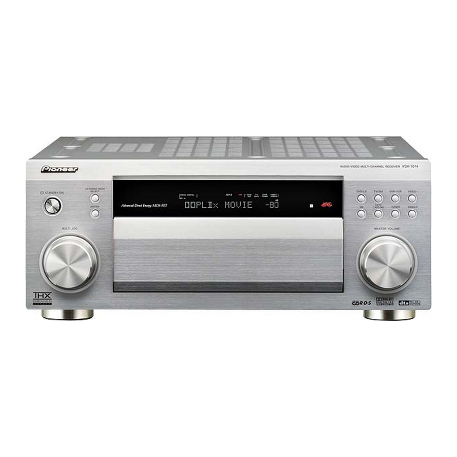
- Page 1 AUDIO/VIDEO MULTI-CHANNEL RECEIVER VSX-1014 VSX-2014i Operating Instructions...
-
Page 2: Operating Environment
If the plug provided is unsuitable for your socket outlets, the plug must be cut off and a suitable plug fitted. Thank you for buying this Pioneer product. Please read through these operating instructions so you will know how to operate your model properly. - Page 3 If the AC plug of this unit does not match the AC outlet you want to use, the plug must be removed and appropriate one fitted. Replacement and mounting of an AC plug on the power supply cord of this unit should be performed only by qualified service personnel.
-
Page 4: Table Of Contents
AC outlet ........22 Operating other Pioneer components ... . . 22 04 Controls and displays Front panel . - Page 5 LFE Attenuator Setup......70 SR+ Setup for Pioneer plasma displays ..71 Multi Room Setup .
-
Page 6: Before You Start
DVD-Video, CD and Video CD discs, all with a single cable. • Seamless video conversion With the Pioneer video converter, you can use a wide range of cables interchangeably, giving you more flexibility when making video connections. Checking what’s in the box... -
Page 7: Installing The Receiver
Before you start • FM wire antenna • Power cord (VSX-2014i model only) • These operating instructions Installing the receiver • When installing this unit, make sure to put it on a level and stable surface. Don’t install it on the following places: –... -
Page 8: 02 5 Minute Guide
5 minute guide Chapter 2: 5 minute guide Introduction to home theater You are probably used to using stereo equipment to listen to music, but may not be used to home theater systems that give you many more options (such as surround sound) when listening to soundtracks. Home theater refers to the use of multiple audio tracks to create a surround sound effect, making you feel like you're in the middle of the action or concert. - Page 9 5 minute guide Connect your speakers. A complete setup of eight speakers (including the subwoofer) is shown here but everyone’s home setup will vary. Simply connect the speakers you have in the manner shown below. The receiver will work with just two stereo speakers (the front speakers in the diagram) but using at least three speakers is recommended, and a complete setup is best.
- Page 10 5 minute guide Make sure that the speaker cable you’re going to use is properly prepared with about 10 mm of insulator stripped from each wire, and the exposed wire strands twisted together (fig. A). To connect a terminal, unscrew the terminal a few turns until there is enough space to insert the exposed wire (fig.
-
Page 11: Automatically Setting Up For Surround Sound (Mcacc)
5 minute guide Automatically setting up for surround sound (MCACC) The Auto MCACC Setup measures the acoustic characteristics of your listening area, taking into account ambient noise, speaker size and distance, and tests for both channel delay and channel level. After you have set up the microphone provided with your system, the receiver uses the information from a series of test tones to optimize the speaker settings and equalization for your... - Page 12 5 minute guide Follow the instructions on-screen. 2. AUTO MCACC • Set microphone • Turn on Sub Woofer • Make sure the microphone is connected. • If you’re using a subwoofer, it is automatically detected every time you switch on the system. Make sure it is on and the volume is turned up.
-
Page 13: Other Problems When Using The Auto Mcacc Setup
5 minute guide Note • If you leave an error message on the screen for over three minutes, or if you cancel the Auto MCACC Setup at any time, the receiver automatically exits and no settings will be made. • Depending on the characteristics of your room, sometimes identical speakers with cone sizes of around 12cm will end up with different size settings. -
Page 14: Connecting Up
Connecting up Chapter 3: Connecting up Important • Before making or changing any connections, switch off the power and disconnect the power cord from the AC outlet. About cable types Analog audio cables Use stereo RCA phono cables to connect analog audio components. -
Page 15: When Making Cable Connections
Connecting up When making cable connections Be careful not to arrange cables in a manner that bends the cables over the top or around this unit. If the cables are laid on top of the unit, the magnetic field produced by the transformers in this unit may cause a humming noise to come from the speakers. -
Page 16: Connecting Digital Audio Components
Connecting up Connecting digital audio components The easiest way to hook up this receiver for surround sound (Dolby Digital and DTS sources) is to use a digital input. You can do this by either coaxial or optical connections (you do not need to do both). The quality of these two types of connections is the same but since some digital components only have one type of digital terminal, it is a matter of matching like with like (for example, the coaxial output from the component to coaxial input on the receiver). -
Page 17: Connecting Analog Audio Components
Connecting up Connecting analog audio components To begin set up, connect your analog audio components (such as a cassette deck) to the jacks. For components you want to record with, you need to hook up four plugs to the receiver (a set of stereo inputs and a set of stereo outputs), but for components that only play, you only need to hook up one set of stereo plugs. -
Page 18: Connecting Video Components
Connecting up Connecting video components Connect your video components to the jacks as shown below. With digital video components (like a DVD player), you must use the connections shown on this page for the video signal, but in order to hear a digital source (like a DVD) you should hook up the audio to a digital input (see page 16). -
Page 19: Connecting Antennas
Connecting up Connecting antennas Connect the AM loop antenna and the FM wire antenna as shown below. To improve reception and sound quality, connect external antennas (see Using external antennas below). Always make sure that the receiver is switched off and unplugged from the wall outlet before making or changing any connections. -
Page 20: Connecting The Speakers
Connecting up Connecting the speakers A complete setup of eight speakers (including the subwoofer) is shown below, but everyone’s home setup will vary. Simply connect the speakers you have in the manner shown below. The receiver will work with just two stereo speakers (the front speakers in the diagram) but using at least three speakers is recommended, and a complete setup is best for surround sound. -
Page 21: Speaker Terminals
Connecting up Speaker terminals 10mm Twist exposed wire strands together. Loosen speaker terminal and insert exposed wire. Make sure that all the bare speaker wire is twisted together and inserted fully into the speaker terminal. Use good quality speaker wire to connect the speakers to the receiver. -
Page 22: Ac Outlet
Operating other Pioneer components AC OUTLET Many Pioneer components have SR CONTROL jacks which can be used to link components together so that you can use just the remote sensor of one component. When you use a remote control, the control signal is (Single) passed along the chain to the appropriate component. -
Page 23: Controls And Displays
Controls and displays Chapter 4: Controls and displays Front panel MODE ENTER MULTI JOG VSX-2014i model TUNER TUNING/ EDIT STATION TUNER MULTI CONTROL SYSTEM SETUP RETURN CONTROL MULTI JOG MULTI JOG PHONES VSX-1014 model TUNER TUNING/ EDIT STATION TUNER MULTI CONTROL SYSTEM SETUP... - Page 24 Controls and displays MULTI JOG dial Use the MULTI JOG dial to select various settings and menu options. STANDBY/ON Switches the receiver between on and standby. LISTENING MODE SELECT Use with the MULTI JOG dial to select the various listening modes (page 30). ENTER Character display See Display on page 25.
-
Page 25: Display
Controls and displays Display SIGNAL DIGITAL DIGITAL AUTO ANALOG SLEEP Speaker indicators (page 59) Lights to indicate the current speaker system, A and/or B. SIGNAL SELECT indicators Lights to indicate the type of input signal assigned for the current component: AUTO Lights when AUTO signal select is on. - Page 26 17 SR Lights when the SR+ control mode has been switched on (see Using the SR+ mode with a Pioneer plasma display on page 66). 18 SLEEP Lights when the receiver is in sleep mode (page 37).
-
Page 27: Remote Control
Controls and displays Remote control INPUT RECEIVER SOURCE SELECT DVD/LD TV/SAT DVR/VCR TV CONT MULTI CONTROL CD-R/TAPE TUNER RECEIVER INPUT ATT FL DIMMER DISC ENTER D.ACCESS CLASS TOP MENU MENU TUNE ENTER BAND T.EDIT TUNE SYSTEM SETUP RETURN GUIDE TV CONTROL INPUT TV VOL TV CH... - Page 28 Controls and displays TV CONTROL buttons These buttons are dedicated to control the TV assigned to the TV CONT button. Thus if you only have one TV to hook up to this system assign it to the TV CONT MULTI CONTROL button.
-
Page 29: Operating Range Of Remote Control Unit
Controls and displays SOURCE Press to turn on/off other components connected to the receiver (see page 53 for more on this). 12 Character display (LCD) This display shows information when transmitting control signals. The following commands are shown when you’re setting the remote to control other components (see Controlling the rest of your system on page 53): SETUP... -
Page 30: Listening To Your System
Listening to your system Chapter 5: Listening to your system Important • VSX-2014i model only – The listening modes and many of the features described in this section are not available when playing SACD or DVD-Audio discs using the i.LINK connection. •... -
Page 31: Using The Home Thx Modes
Listening to your system Note • If the Extended mode (page 34) is switched to OFF, or the surround back speakers are set to NO (this happens automatically if the Surround back speaker setting on page 38 is set to anything but Normal (SB)), 2 Pro Logic IIx becomes 2 Pro Logic II (5.1 channel sound). -
Page 32: Dolby Pro Logic Iix Music Settings
Listening to your system • If you press ADV. SURR when the headphones are connected, the PhonesSurround mode will automatically be selected. • You can’t use the Advanced Surround effects with 88.2/96kHz PCM or DTS 96kHz/24 bit sources. • When an Advanced Surround listening mode is selected, the effect level can be adjusted in the range of 10 to 90 by pressing EFFECT/CH SEL (until EFFECT shows in the display). -
Page 33: Listening With Acoustic Calibration Eq
Listening to your system Listening with Acoustic Calibration • Default setting: OFF / ALL CH ADJ (after the Auto MCACC Setup or EQ Auto Setting) You can listen to sources using the Acoustic Calibration Equalization set in Automatically setting up for surround sound (MCACC) on page 11 or Acoustic Calibration EQ on page 41. -
Page 34: Using The Surround Back Channel (Extended Mode)
Listening to your system Using the surround back channel (Extended mode) • Default setting: Extended ON You can have the receiver automatically use 6.1 or 7.1 decoding for 6.1 encoded sources (for example, Dolby Digital EX or DTS-ES), or you can choose to always use 6.1 or 7.1 decoding (for example, with 5.1 encoded material). -
Page 35: Using The Virtual Surround Back Mode (Virtualsb)
Listening to your system Using the Virtual Surround Back mode (VirtualSB) When you’re not using surround back speakers, selecting this mode allows you to hear a virtual surround back channel through your surround speakers. For example, you can choose to listen to sources with no surround back channel information (for example, 5.1 encoded material) with emulated 6.1 encoding (VirtualSB ON). -
Page 36: Using Loudness And Midnight Listening
Listening to your system Using Loudness and Midnight listening The Loudness listening feature can be used to get good bass and treble from music sources at low volume levels. The Midnight listening feature allows you to hear effective surround sound of movies at low volume levels. The effect automatically adjusts according to the volume at which you’re listening. -
Page 37: Playing Other Sources
Listening to your system Note • You can only use the tone controls when STEREO/ DIRECT is selected. DIRECT will switch to STEREO when the tone controls are used. Playing other sources INPUT RECEIVER SOURCE SELECT DVD/LD TV/SAT DVR/VCR TV CONT MULTI CONTROL CD-R/TAPE TUNER... -
Page 38: The System Setup Menu
The System Setup menu Chapter 6: The System Setup menu Making receiver settings from the System Setup menu The following section shows you how to make detailed settings to specify how you’re using the receiver (for example, if you want to set up two speaker systems in separate rooms), and also explains how to fine-tune individual speaker system settings to your liking. -
Page 39: Manual Mcacc Speaker Setup
The System Setup menu Select the surround back speaker setting. 1. Surround Back System Surround Back Output Normal(SB) • Normal (SB) – Select for normal home theater use with surround back speakers in your main (speaker system A) setup. • Second Zone – Select to use the (surround back) B speaker terminals to listen to stereo playback in another room (see Second Zone speaker B setup on page 59). -
Page 40: Fine Channel Level
The System Setup menu Fine Channel Level • Default setting: 0dB (all channels) You can achieve better surround sound by properly adjusting the overall balance of your speaker system. The following setting can help you make detailed adjustments that you may not achieve using the Manual speaker setup on page 43. -
Page 41: Acoustic Calibration Eq
The System Setup menu When it sounds like the delay settings are matched up, press ENTER to confirm and continue to the next channel. • For comparison purposes, the reference speaker will change depending on which speaker you select. • If you want to go back and adjust a channel, simply (cursor up/down) to select it. - Page 42 The System Setup menu Select ‘OK’ to copy and confirm. 3d. EQ Data Copy CUSTOM1 [ ALL CH ADJ. ] CUSTOM2 Start Copy Enter :Start Copy Setting the Acoustic Calibration EQ manually Before manually adjusting the Acoustic Calibration EQ, we recommend copying the ALL CH ADJUST or the FRONT ALIGN settings from the auto setup above (or from Automatically setting up for surround sound (MCACC) on page 11) to one of the custom settings.
-
Page 43: Manual Speaker Setup
The System Setup menu Select the setting you want to check. 3g. EQ Data Check Type [ ALL CH ADJUST [ Left 40Hz : 0.0dB 125Hz : 0.0dB 250Hz : 0.0dB 4kHz : 0.0dB 13kHz : 0.0dB TRIM : 0.0dB •... -
Page 44: Speaker Setting
The System Setup menu Speaker Setting Use this setting to specify your speaker configuration (size, number of speakers). It is a good idea to make sure that the settings made in Automatically setting up for surround sound (MCACC) on page 11 are correct. Select ‘Speaker Setting’... -
Page 45: Crossover Network
The System Setup menu Crossover Network • Default setting: 80Hz This setting decides the cutoff between bass sounds playing back from the speakers selected as LARGE, or the subwoofer, and bass sounds playing back from those selected as SMALL. It also decides where the cutoff will be for bass sounds in the LFE channel. -
Page 46: Speaker Distance
The System Setup menu Note • If you are using a Sound Pressure Level (SPL) meter, take the readings from your main listening position and adjust the level of each speaker to 75 dB SPL (C- weighting/slow reading). • The subwoofer test tone is output at low volumes. You may need to adjust the level after testing with an actual soundtrack. -
Page 47: Using The Tuner
Using the tuner Chapter 7: Using the tuner Listening to the radio The following steps show you how to tune in to FM and AM radio broadcasts using the automatic (search) and manual (step) tuning functions. If you already know the frequency of the station you want, see Tuning directly to a station below. -
Page 48: Saving Station Presets
Using the tuner Saving station presets If you often listen to a particular radio station, it's convenient to have the receiver store the frequency for easy recall whenever you want to listen to that station. This saves the effort of manually tuning in each time. This unit can memorize up to 30 stations, stored in three banks, or classes, (A, B and C) of 10 stations each. -
Page 49: An Introduction To Rds
Using the tuner An introduction to RDS Radio Data System, or RDS as it’s usually known, is a system used by FM radio stations to provide listeners with various kinds of information—the name of the station and the kind of show they’re broadcasting, for example. -
Page 50: Searching For Rds Programs
Using the tuner Searching for RDS programs One of the most useful features of RDS is the ability to search for a particular kind of radio program. You can search for any of the program types listed on the previous page. -
Page 51: Clearing All Stations From The Rds And Eon Searches
Using the tuner Clearing all stations from the RDS and EON searches The receiver will automatically register an identifying marker (called a PI code) for any station you input into the memory classes which can receive RDS or EON data. If you want to remove the currently memorized stations from RDS and EON searches, you can do it by erasing the PI codes. -
Page 52: Making Recordings
Making recordings Chapter 8: Making recordings Making an audio or a video recording You can make an audio or a video recording from the built-in tuner, or from an audio or video source connected to the receiver (such as a CD player or TV). Keep in mind you can’t make a digital recording from an analog source or vice-versa, so make sure the components you are recording to/from are hooked up in... -
Page 53: Controlling The Rest Of Your System
• If you assign the TUNER function to another component, you will have to reassign it to the Pioneer preset code to use this receiver’s built-in tuner. • You can cancel or exit any of the steps by pressing RECEIVER. -
Page 54: Programming Signals From Other Remote Controls
Controlling the rest of your system Programming signals from other remote controls If the preset code for your component is not available, or the available preset codes do not operate correctly, you can program signals from the remote control of another component. -
Page 55: Erasing One Of The Remote Control Button Settings
Controlling the rest of your system Erasing one of the remote control button settings This erases one of the buttons you have programmed and restores the button to the factory default. While pressing the RECEIVER button, press and hold the 1 button. The remote LCD display shows SETUP. -
Page 56: Controls For Tvs
Controlling the rest of your system Controls for TVs This remote control can control components after entering the proper codes or teaching the receiver the commands (see Setting the remote to control other components on page 53 for more on this). Use the MULTI CONTROL buttons to select the component. -
Page 57: Controls For Other Components
Controlling the rest of your system Controls for other components This remote control can control these components after entering the proper codes or teaching the receiver the commands (see Setting the remote to control other components on page 53 for more on this). Use the MULTI CONTROL buttons to select the component. - Page 58 Controlling the rest of your system Button (s) Function Pauses the tape. Stops the tape. ENTER Starts playback. Fast rewinds/fast forwards the tape. & Navigates DVD menu/options. ENTER GUIDE Press to access the DVD player setup screen. CH +/– Selects channels. Selects tracks.
-
Page 59: Other Connections
Other connections Chapter 10: Other connections Caution • Before making or changing the connections, switch off the power and disconnect the power cord from the power outlet. Plugging in components should be the last connection you make with your system. •... -
Page 60: Bi-Amping Your Front Speakers
Other connections Bi-amping your front speakers Bi-amping is when you connect the high frequency driver and low frequency driver of your speakers to different amplifiers (in this case, to both front and surround back terminals) for better crossover performance. Your speakers must be bi-ampable to do this (having separate terminals for high and low) and the sound improvement will depend on the kind of speakers you’re using. -
Page 61: Connecting Additional Amplifiers
Other connections Connecting additional amplifiers This receiver has more than enough power for any home use, but it’s possible to add additional amplifiers to every channel of your system using the pre-outs. Make the connections shown below to add amplifiers to power your speakers. -
Page 62: Using The Sub Room Controls
• If you are using a Pioneer amplifier in the sub room, cover up the remote sensor to avoid changing the settings when controlling the sub room. -
Page 63: Using The I.link Interface
• When the MULTI ROOM OUT jacks are connected to a sub room amplifier with a remote sensor and Pioneer CONTROL terminals (page 22), both the IR receiver and the amplifier may receive remote control commands (making correct operation impossible) during multi-room operation. -
Page 64: About I.link
T V / FRONT About PQLS rate control SUR- DVD/ ROUND ASSIGNABLE 〜 Pioneer's PQLS (Precision Quartz Lock System) COMPONENT VIDEO S-VIDEO VIDEO VIDEO technology provides high-precision digital audio from DVD-A, SACD and audio CD sources when you use the i.LINK interface. -
Page 65: Switching Components On And Off Using The 12 Volt Trigger
72. Using this receiver with a Pioneer plasma display If you have a Pioneer plasma display, you can use an SR+ cable (see note below) to connect it to this unit and take advantage of various convenient features, such as automatic video input switching of the plasma display when the input is changed. -
Page 66: Using The Sr+ Mode With A Pioneer Plasma Display
Other connections Important • If you connect to a Pioneer plasma display using an SR+ cable, you will need to point the remote control at the plasma display remote sensor to control the receiver. In this case, you won’t be able to control the receiver using the remote control if you switch the plasma display off. -
Page 67: Other Settings
Other Settings Chapter 11: Other Settings The Input Assign menu You only need to make settings in the Input Assign menu if you didn’t hook up your digital equipment according to the default settings for the digital inputs, or if you have connected equipment using component video cables or VSX-2014i only) an i.LINK connection. - Page 68 Other Settings Assigning the component video inputs • Default settings: Component 1 – OFF Component 2 – OFF If you used component video cords to connect your video equipment you must tell the receiver which device it is, or else you may see the S-video or composite video input instead of the component video signal.
-
Page 69: The Other Setup Menu
• LFE ATT Setup – Choose the attenuator level for the LFE channel (LFE Attenuator Setup below). • SR+ Setup – Specify how you want to control your Pioneer plasma display (SR+ Setup for Pioneer plasma displays on page 71). The following are available with the VSX-2014i model: •... -
Page 70: Dynamic Range Control Setup
Other Settings Dynamic Range Control Setup • Default setting: OFF This setting specifies the amount of dynamic range adjustment to Dolby Digital and DTS movie soundtracks. You may want to use this when listening to surround sound at low volumes. Select ‘DRC Setup’... -
Page 71: Sr+ Setup For Pioneer Plasma Displays
See also Using this receiver with a Pioneer plasma display on page 65 and Using the SR+ mode with a Pioneer plasma display on page 66. Select ‘SR+ Setup’ from the Other Setup menu. -
Page 72: 12 Volt Trigger Setup
Other Settings Select the type of IR receiver you’re using. 6e. Multi Room Setup Volume Level IR Setting • Setting 1 – Use this setting for most IR receivers. • Setting 2 – Use this setting if the IR receiver you’re using doesn’t seem to work after selecting Setting 1. -
Page 73: Additional Information
Sometimes the trouble may lie in another component. Investigate the other components and electrical appliances being used. If the trouble cannot be rectified even after exercising the checks listed below, ask your nearest Pioneer authorized independent service company to carry out repair work. Power... -
Page 74: No Sound
Additional information No sound Symptom No sound is output when an input source is selected. No sound output from the front speakers. No sound from the surround or center speakers. No sound from surround back speakers. No sound from subwoofer. Cause •... -
Page 75: Other Audio Problems
Additional information Symptom Cause • The speaker setting has been set to NO. No sound from one speaker. • The speaker level is too low. • The speaker isn’t connected properly. • The source has no sound output for that channel. -
Page 76: Video
Additional information Symptom Can't record audio. Subwoofer output is very low. The signal is not downmixed when listening to a multichannel DVD-Audio disc (for example, you only hear the front left and right channels when listening in stereo). Everything seems to be set up correctly, but the playback sound is odd. -
Page 77: Settings
• The low-frequency noise could have been caused by an air conditioner or motor. Switch off all appliances in the room and rerun the Auto MCACC Setup. • Ask your Pioneer dealer to disable the key lock. • Turn the receiver off and check the 12V trigger connection. -
Page 78: Remote Control
• Input the correct preset code. • Reset the proper system settings. • Reinsert the SR cable, making sure it’s connected to the right jack (see Operating other Pioneer components on page 22). • Make sure an analog connection has been made between the units. -
Page 79: I.link Interface
Additional information i.LINK interface VSX-2014i model only Symptom Cause No sound is output. • An output signal is not produced from the i.LINK connector on the source player. • The selected component is not compatible with i.LINK audio. • The input signal is set to DIGITAL or ANALOG. -
Page 80: Resetting The Main Unit
Additional information Message PQLS OFF PQLS ON UNKNOWN Note • If the unit does not operate normally due to external effects such as static electricity disconnect the power plug from the outlet and insert again to return to normal operating conditions. Resetting the main unit Use this procedure to reset all the receiver’s settings to the factory default. -
Page 81: Surround Sound Formats
Additional information Surround sound formats Below is a brief description of the main surround sound formats you’ll find on DVDs, satellite, cable and terrestrial broadcasts, and video cassettes. Dolby The Dolby technologies are explained below. See www.dolby.com for more detailed information. Dolby Digital Dolby Digital is a multichannel digital audio coding system widely used in cinemas, and in the home for DVD... -
Page 82: About Thx
Additional information About THX The THX technologies are explained below. See www.thx.com for more detailed information. THX Cinema processing THX is an exclusive set of standards and technologies established by the world-renowned film production company, Lucasfilm Ltd. THX grew from George Lucas' personal desire to make your experience of the film soundtrack, in both movie theatres and in your home theatre, as faithful as possible to what the director... -
Page 83: Specifications
Additional information Specifications Amplifier section Continuous Power Output (Stereo) Front..150 W + 150 W (DIN 1kHz, THD 1%, 6Ω) 120 W + 120 W (DIN 1kHz, THD 1%, 8Ω) Continuous Power Output (Multichannel) Front. - Page 84 253 Alexandra Road, #04-01, Singapore 159936 TEL: 65-6472-7555 PIONEER ELECTRONICS AUSTRALIA PTY. LTD. 178-184 Boundary Road, Braeside, Victoria 3195, Australia, TEL: (03) 9586-6300 PIONEER ELECTRONICS DE MEXICO S.A. DE C.V. Blvd.Manuel Avila Camacho 138 10 piso Col.Lomas de Chapultepec, Mexico,D.F. 11000 TEL: 55-9178-4270 K002_A_En <04F00001>...