Table of Contents
Advertisement
Quick Links
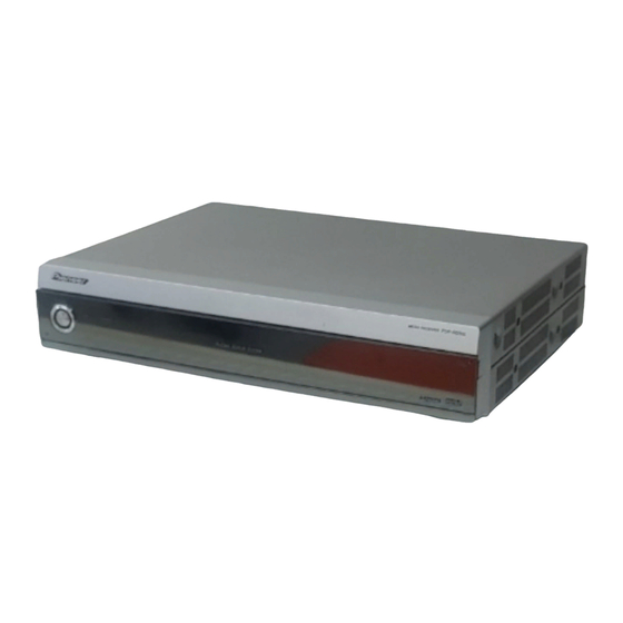
MEDIA RECEIVER
PDP-R05G
THIS MANUAL IS APPLICABLE TO THE FOLLOWINGMODEL(S) AND TYPE(S).
Model
Type
PDP-R05G
TLDPFR
Please connect it to the PLASMA DISPLAY PDP-505PG or PDP-435PG for adjustment and
operation inspection.
For details, refer to
"Important Check Points for Good
PIONEER CORPORATION
PIONEER ELECTRONICS (USA) INC. P.O. Box 1760, Long Beach, CA 90801-1760, U.S.A.
PIONEER EUROPE NV Haven 1087, Keetberglaan 1, 9120 Melsele, Belgium
PIONEER ELECTRONICS ASIACENTRE PTE. LTD. 253 Alexandra Road, #04-01, Singapore 159936
PIONEER CORPORATION 2004
POWER
ON
Power Requirement
AC110-240V
4-1, Meguro 1-chome, Meguro-ku, Tokyo 153-8654, Japan
STANDBY
PDP-R05G
Servicing".
ORDER NO.
PROVISIONAL
Remarks
T-ZZK NOV. 2004 printed in Japan
Advertisement
Table of Contents

Related Manuals for Pioneer PDP-R05G


Summary of Contents for Pioneer PDP-R05G
- Page 1 PIONEER CORPORATION 4-1, Meguro 1-chome, Meguro-ku, Tokyo 153-8654, Japan PIONEER ELECTRONICS (USA) INC. P.O. Box 1760, Long Beach, CA 90801-1760, U.S.A. PIONEER EUROPE NV Haven 1087, Keetberglaan 1, 9120 Melsele, Belgium PIONEER ELECTRONICS ASIACENTRE PTE. LTD. 253 Alexandra Road, #04-01, Singapore 159936 PIONEER CORPORATION 2004 T-ZZK NOV.
-
Page 2: Safety Information
PIONEER Service Manual. A subscription to, or additional copies Also test with plug reversed of, PIONEER Ser vice Manual may be obtained at a (Using AC adapter Earth nominal charge from PIONEER. plug as required) - Page 3 To protect products from damages or failures during transit, the shipping mode should be set or the shipping screws should be installed before shipment. Please be sure to follow this method especially if it is specified in this manual. PDP-R05G...
-
Page 4: Table Of Contents
7. GENERAL INFORMATION ........................... 128 7.1 DIAGNOSIS ............................128 7.1.1 TROUBLE SHOOTING ........................128 7.1.2 DISASSEMBLY..........................138 7.2 EXPLANATION ............................140 7.2.1 PROCESSING IN ABNORMALITY..................... 140 7.3 PARTS..............................144 7.3.1 IC ..............................144 7.4 CLEANING............................. 177 8. PANEL FACILITIES ............................178 PDP-R05G... -
Page 5: Specifications
1. SPECIFICATIONS Item Media Receiver, Model: PDP-R05G Color System PAL/SECAM/NTSC/4.43 NTSC//PAL-M/PAL-N TV Function Receiving System PAL: B/G, D/K, I, M, N SECAM: B/G, D/K NTSC: M 4.43NTSC: M Tuner VHF/UHF 44.25-863.25 MHz CATV Hyper-band, S1–S41ch Auto Channel Preset 99 ch (Normal), 68 ch (Air, US type), 125 ch (Cable, US type), Auto Preset... -
Page 6: Exploded Views And Parts List
For the applying amount of lubricants or glue, follow the instructions in this manual. (In the case of no amount instructions, apply as you think it appropriate.) 2.1 PACKING SECTION ×4 ×4 PDP-R05G... - Page 7 Pad R AHA2371 IM Pad AHB1253 Top Pad AHB1256 Accessory Box AHC1053 Carton G AHD3249 NSP 17 Literature Bag AHG1303 Vinyl Bag AHG1310 Vinyl Bag AHG1337 Laminated Sheet AHG1350 Air Capsule Bag AHG1351 Screw PMB40P120FTB Caution Card (10L) ARM1234 PDP-R05G...
-
Page 8: Exterior Section
2.2 EXTERIOR SECTION 58 59 Refer to "2.3 FRONT PANEL SECTION". PDP-R05G... - Page 9 Circuit Board Spacer AEC1964 Heatsink HDMI ANH1618 Gasket F ANK1722 HDMI Shield ANG2646 Terminal Panel G ANC2365 > Gasket ANK1730 S Shield ANG2713 Mini Card Spacer AEC1959 SR Holder ANG2567 Base Chassis ANA1811 > Gasket ANK1728 > Gasket ANK1729 PDP-R05G...
-
Page 10: Front Panel Section
2.3 FRONT PANEL SECTION PDP-R05G... - Page 11 AC SW Assy AWZ6783 SW Holder ANG2670 SW Spring ABH1109 Power Button AAD4128 Front Panel Assy G AXG1023 Front Panel (G) AMB2831 Pioneer Badge VAM1124 Door AAN1473 Escutcheon Ring AAD4130 Panel (E) AAK2826 Sealing Sheet S (GC) AAL2555 Sealing Sheet (G) AAL2549...
-
Page 12: Block Diagram And Schematic Diagram
SM5301 BS-TFB IC8003 IC6604 TC4052 BA7078AF IC8004 Mon.Out HDMI_LCH HDMI_RCH TC4052RFT PCM1742KE IC6803 SUBC_Y AN15852 AV_SW0 AV_SW1 SII9993CTG100 IC6881 SDA_AV SCL_AV IC8005 HD64F368 IC8705 24LC01B TXD_IF IC8703 IC8702 PST3630UR RXD_IF REQ_IF RESET CE_IF BUSY_IF RELAY POWER SUPPLY HDMI UNIT PDP-R05G... - Page 13 BE70PFV IC3_BUSY IC7152 IC7151 IC3_REQ CLK_IC2 TXD_IC2 RXD_IC2 IC2_OE IC7207 IC2_CE CN9301 MB91F355PMT-G PLASMA DISPLAY IC7202 SDA_HDCP BLACK TC74VHC125FT SDL_HDCP UARTRXD NJM12904V IC7301 UARTTXD ASSY RESET 24LC128(I)SN PST3628UR IC7205 IC7203 RDV2 GDV2 M5291FP IC7302 BDV2 CKDV2 DEDV2 VDV2 HDV2 PDP-R05G...
-
Page 14: Mr Main Board Assy
TC74VHC126FT HD/VD_SUB RESETX3 CLAMP_SUB IC6602 R/G/B_TXT_SUB HD_SUB IC6601 AD9883AKST-110 SUBC_Y/PB/PR, R/G/ SM5301BS AD SUB B_OUT LPF SUB PCA_H/V_SUB SUB_Y/C SUBC_Y IC6255 HD/VD_SUB PD0278A HD/VD_TXT_SUB CN7453 Y/C SEP. AKM1232 TRST,RST R/G/B_DA_SUB CHROMA DEC. To/From RA/GA/BA_SUB[0:7],CK/DE/FLD_SUB TCK,TMS JTAG/ SDI UARTTXD DBI,SDIJTAG,TRST_IC3,TDI,UARTRXD PDP-R05G... - Page 15 IC6607 TC74VHC126FT HD1/VD1_SUB EXDIO[0:15] IC7152 SYNC SEL MBM20PL3200BE70PFV SDRAM IC7101 IC6604 PE5855A RA/GA/BA CN7401 IC7401 BA7078AF RESIZE MIX [0:9],VD0 AKP1250 SII170BCLG64 SYNC SEP.SUB TMDS[0:7] To/From DVI TX HD/DE_OUT IC6603 TC74VHC126FT HD2/VD2_SUB IC7404 CLK0 SYNC SEL TC74VCX08FT IC7403 DE0,HD0 TC74VCX574FT PDP-R05G...
-
Page 16: Av Board Assy
UCOM VIDEO_1 V1_C TEXT[0:47] V2_Y VIDEO_2 V2_C RESET IC8901 V3_Y PST9230N VIDEO_3 V3_C CN9502 CN8653 YUV_SW[0:63] V4_Y V4_Y V4_C V4_C V4_V V4_V VIDEO_4 V4_L V4_L IC8005 V4_R V4_R AN15852A PC_LCH/ PC_LCH/RCH PC_R/G/B PC_R/G/B PC_H/V PC_H/V AKM1201 FRONT_PANEL FRONT ASSY PDP-R05G... - Page 17 TXT_RGB_DIG[0:15] IC8907 PIXEL_CLK_IN TC7SH04FU CLAMP_MAIN IC8702 UIF_UCOM[1:72] HD64F3687FP UIF_UCOM[1:72] UIFCOFM CN8652 IC8902 WE_TXT AKM1201 TC7W126FU To/From MAIN IC9104 IC9101 HY57V641620HGT MBM29LV160TE IC8906 -90FTN TA1287 R/G/B_TXT_MAIN R/G/B_MAIN_ANG R/G/B_DA_MAIN MAIN_Y/C SUB_Y/C MAINC_Y/PB/PR SUBC_Y/PB/PR HD/VD_TXT IC8001 PC_V DSUB_DET TC72H124FU IC7701 PCA_H/V TC74VHC125FT PDP-R05G...
-
Page 18: Power Supply Unit
3.1.4 POWER SUPPLY UNIT POWER SUPPLY UNIT PDP-R05G... - Page 19 PDP-R05G...
-
Page 20: Overall Wiring Connection Diagram
3.2 OVERALL WIRING CONNECTION DIAGRAM 1/2 - FRONT ASSY (AWZ6975) REG ASSY (AWZ6833) 1/8 - AV BOARD ASSY (AWZ6982) ADD1213 SR ASSY LED ASSY (AWZ6817) (AWZ6816) PDP-R05G... - Page 21 Therefore, when replacing, be sure to use parts of identical AXM1045 designation. • : The power supply is shown with the marked box. AKM1274 1/13 - 13/13 MR MAIN BOARD ASSY (AWV2157) MDR ASSY (AWZ6778) AC SW ASSY (AWZ6783) POWER SUPPLY UNIT (AXY1093) PDP-R05G...
-
Page 22: Mr Main Board Assy (1/13)
3.3 MR MAIN BOARD ASSY (1/13) 1/13 MR MAIN BOARD ASSY (AWV2157) ¶ GR BLOCK NOT USED C SYNC SEP. V SYNC SEP. 13/13 13/13 1/13 PDP-R05G... - Page 23 NOT USED 2/13-9/13, 11/13-13/13 (Ghosts Reduce IC) 2/13, 3/13 1/13 PDP-R05G...
-
Page 24: Mr Main Board Assy (2/13)
3.4 MR MAIN BOARD ASSY (2/13) 2/13 MR MAIN BOARD ASSY (AWV2157) ¶ MICHAEL MAIN BLOCK 8/13, 11/13 +polality 7/13, 8/13 4/13, 7/13, 8/13 1/13, 3/13 2/13 PDP-R05G... - Page 25 3/13 13/13 13/13 13/13 3/13, 8/13, 13/13 13/13 3/13 3/13, 8/13, 9/13, 13/13 1/13, 3/13-9/13, 11/13-13/13 3/13, 6/13, 7/13, 13/13 2/13 PDP-R05G...
-
Page 26: Mr Main Board Assy (3/13)
3.5 MR MAIN BOARD ASSY (3/13) +polality 9/13 7/13, 9/13 5/13, 7/13, 9/13 1/13, 2/13 3/13 PDP-R05G... - Page 27 3/13 MR MAIN BOARD ASSY (AWV2157) ¶ MICHAEL SUB BLOCK 13/13 13/13 13/13 2/13, 8/13, 13/13 2/13 8/13 2/13, 8/13, 9/13, 13/13 1/13, 2/13, 4/13-9/13, 11/13-13/13 2/13, 6/13, 7/13, 13/13 3/13 PDP-R05G...
-
Page 28: Mr Main Board Assy (4/13)
¶ AD MAIN BLOCK H : Ch B (TEXT RGB) L : Ch A (COMPONENT / PC RGB) H : FILTER THROUGH L : FILTER ON 13/13 13/13 13/13 13/13 SELECTOR 13/13 2/13, 4/13, 7/13, 8/13 2/13, 7/13, 8/13 8/13 4/13 PDP-R05G... - Page 29 2/13, 7/13, 8/13 8/13 8/13, 13/13 2/13, 7/13, 8/13 2/13, 4/13, 7/13, 8/13 5 → 3.3V CONVERTER 1/13-3/13, 5/13-9/13, SYNC. SELECTOR 11/13-13/13 H : FILTER THROUGH L : FILTER ON 2/13, 13/13 8/13 L : COMPONENT / PC RGB 4/13 PDP-R05G...
-
Page 30: Mr Main Board Assy (5/13)
¶ AD SUB BLOCK H : Ch B (TEXT RGB) L : Ch A (COMPONENT / PC RGB) H : FILTER THROUGH L : FILTER ON 13/13 13/13 13/13 13/13 13/13 3/13, 5/13, 7/13, 9/13 13/13 3/13, 7/13, 9/13 5/13 9/13 PDP-R05G... - Page 31 3/13, 7/13, 9/13 9/13 3/13, 7/13, 9/13 3/13, 5/13, 7/13, 9/13 1/13-4/13, 6/13-9/13, 5 + 3.3V CONVERTER 11/13-13/13 SYNC. SELECTOR H : FILTER THROUGH L : FILTER ON 3/13, 13/13 3/13, 13/13 9/13 L : COMPONENT / PC RGB 5/13 PDP-R05G...
-
Page 32: Mr Main Board Assy (6/13)
3.8 MR MAIN BOARD ASSY (6/13) 6/13 MR MAIN BOARD ASSY (AWV2157) ¶ HDMI RX BLOCK 6/13 PDP-R05G... - Page 33 12/13 7/13 13/13 7/13 2/13, 3/13, 7/13, 13/13 1/13-5/13, 7/13-9/13, 11/13-13/13 7/13 13/13 7/13 13/13 6/13 PDP-R05G...
-
Page 34: Mr Main Board Assy (7/13)
3.9 MR MAIN BOARD ASSY (7/13) 7/13 MR MAIN BOARD ASSY (AWV2157) ¶ ROZ BLOCK 2/13, 3/13, 6/13, 13/13 1/13-6/13, 8/13, 9/13, 11/13-13/13 6/13 7/13 PDP-R05G... - Page 35 2/13, 4/13, 8/13 3/13, 5/13, 9/13 2/13, 8/13 3/13, 9/13 6/13 7/13 PDP-R05G...
-
Page 36: Mr Main Board Assy (8/13)
3.10 MR MAIN BOARD ASSY (8/13) 8/13 MR MAIN BOARD ASSY (AWV2157) ¶ CELIA BLOCK 9/13 12/13 9/13 2/13, 4/13, 7/13 8/13 PDP-R05G... - Page 37 9/13 9/13 1/13-7/13, 9/13, 9/13 11/13-13/13 2/13, 3/13, 9/13, 13/13 9/13 3/13 2/13, 3/13, 13/13 13/13 4/13 4/13 2/13, 4/13, 7/13 2/13, 4/13, 7/13, 11/13 8/13 PDP-R05G...
-
Page 38: Mr Main Board Assy (9/13)
3.11 MR MAIN BOARD ASSY (9/13) 9/13 MR MAIN BOARD ASSY (AWV2157) ¶ MIKE BLOCK 12/13 10/13 Flash Address, Data 8/13 8/13 9/13 PDP-R05G... - Page 39 8/13, 13/13 11/13, 13/13 13/13 2/13, 3/13, 8/13, 13/13 1/13-8/13, 11/13-13/13 13/13 5/13 5/13 3/13, 5/13, 7/13 8/13 3/13 3/13, 5/13, 7/13 9/13 PDP-R05G...
-
Page 40: Mr Main Board Assy (10/13)
3.12 MR MAIN BOARD ASSY (10/13) 10/13 MR MAIN BOARD ASSY (AWV2157) ¶ MIKE FLASH BLOCK 9/13 10/13 PDP-R05G... - Page 41 PDP-R05G...
-
Page 42: Mr Main Board Assy (11/13)
3.13 MR MAIN BOARD ASSY (11/13) 11/13 MR MAIN BOARD ASSY (AWV2157) ¶ MAIN UCOM BLOCK AKM1274 CN9601 TRAP 13/13 11/13 PDP-R05G... - Page 43 1/13-9/13, 12/13, 13/13 9/13, 13/13 MOTOR AKM1274 11/13 PDP-R05G...
-
Page 44: Mr Main Board Assy (12/13)
3.14 MR MAIN BOARD ASSY (12/13) 12/13 MR MAIN BOARD ASSY (AWV2157) ¶ MR I/F BLOCK 13/13 6/13 CN9302 8/13 13/13 12/13 PDP-R05G... - Page 45 9/13 9/13 1/13-9/13, 11/13, 13/13 12/13 PDP-R05G...
-
Page 46: Mr Main Board Assy (13/13)
3.15 MR MAIN BOARD ASSY (13/13) 13/13 MR MAIN BOARD ASSY (AWV2157) ¶ REGULATOR BLOCK AKM1301 CN8651 13 14 2/13 CN8652 2/13 3/13 3/13 4/13 R7427 5/13 6/13, 13/13 5/13 4/13 1/13 12/13 1/13-9/13, 11/13, 12/13 4/13,8/13 CN8654 6/13 12/13 6/13 6/13 13/13 PDP-R05G... - Page 47 8/13, 9/13 9/13 2/13 2/13, 3/13, 8/13, 9/13 9/13 11/13 9/13 8/13 2/13, 3/13, 2/13, 6/13 3/13, 9/13 8/13 9/13, 11/13 1/13-9/13, 11/13, 12/13 2/13, 4/13 2/13, 4/13 3/13, 5/13 3/13, 5/13 6/13 13/13 PDP-R05G...
-
Page 48: Av Board Assy (1/8)
3.16 AV BOARD ASSY (1/8) AV BOARD ASSY (AWZ6982) ¶ TUNER BLOCK 3/8-5/8 2/8-8/8 ANALOG PDP-R05G... - Page 49 PDP-R05G/TLDFR PDP-R05G...
-
Page 50: Av Board Assy (2/8)
3.17 AV BOARD ASSY (2/8) AV BOARD ASSY (AWZ6982) ¶ AV I/O BLOCK 3/8, 7/8 PDP-R05G... - Page 51 3/8, 5/8 4/8, 5/8 3/8, 5/8 PDP-R05G...
-
Page 52: Av Board Assy (3/8)
3.18 AV BOARD ASSY (3/8) AV BOARD ASSY (AWZ6982) ¶ AV SW BLOCK 2/8, 5/8 1/8, 2/8, 4/8-8/8 1/8, 4/8, 5/8 2/8, 7/8 5/8, 8/8 PDP-R05G... - Page 53 2/8, 5/8 5/8, 7/8 1/8, 2/8, 4/8-8/8 PDP-R05G...
-
Page 54: Av Board Assy (4/8)
3.19 AV BOARD ASSY (4/8) AV BOARD ASSY (AWZ6982) ¶ AV_REG BLOCK PDP-R05G... - Page 55 CN8505 CN8506 1/8-3/8, 5/8-8/8 1/8, 3/8, 5/8 PDP-R05G...
-
Page 56: Av Board Assy (5/8)
3.20 AV BOARD ASSY (5/8) AV BOARD ASSY (AWZ6982) ¶ BOARD IF BLOCK 2/8, 3/8 CN9502 1/8, 3/8, 4/8 1/8-4/8, 6/8-8/8 CN9651 CN9452 PDP-R05G... - Page 57 13/13 CN7454 13/13 CN7455 1/8, 3/8, 4/8 2/8,4/8 2/8, 3/8 2/8, 3/8 PDP-R05G...
-
Page 58: Av Board Assy (6/8)
3.21 AV BOARD ASSY (6/8) AV BOARD ASSY (AWZ6982) ¶ IF UCOM BLOCK 1/8-5/8, 7/8, 8/8 PDP-R05G... - Page 59 PDP-R05G...
-
Page 60: Av Board Assy (7/8)
3.22 AV BOARD ASSY (7/8) ¶ TELETEXT BLOCK AV BOARD ASSY (AWZ6982) 3/8, 5/8 1/8-6/8, 8/8 PDP-R05G... - Page 61 PDP-R05G...
-
Page 62: Av Board Assy (8/8)
3.23 AV BOARD ASSY (8/8) AV BOARD ASSY (AWZ6982) ¶ MEMORY_SW BLOCK 1/8, 6/8 PDP-R05G... - Page 63 PDP-R05G...
-
Page 64: Mdr Assy
3.24 MDR ASSY MDR ASSY (AWZ6778) PDP-R05G... - Page 65 CKS3830 PDP-R05G...
-
Page 66: Sr Assy
3.25 SR ASSY SR ASSY (AWZ6817) PDP-R05G... - Page 67 CKS3826 CN8658 PDP-R05G...
-
Page 68: Front Assy (1/2)
3.26 FRONT ASSY (1/2) FRONT ASSY (AWZ6975) ¶ FRONT BLOCK PDP-R05G... - Page 69 CN8653 PDP-R05G...
-
Page 70: Front Assy (2/2)
3.27 FRONT ASSY (2/2) FRONT ASSY (AWZ6975) ¶ SENSOR BLOCK 11/13 CN7202 PDP-R05G... -
Page 71: Led Assy
3.28 LED ASSY LED ASSY (AWZ6816) CN8656 PDP-R05G... -
Page 72: Reg Assy
3.29 REG ASSY REG ASSY (AWZ6833) CP51 13/13 CN7451 PDP-R05G... - Page 73 CN8504 CN8503 PDP-R05G...
-
Page 74: Power Supply Unit
3.30 POWER SUPPLY UNIT POWER SUPPLY UNIT (AXY1093) LIVE NEUTRAL AC SW ASSY (AWZ6783) LIVE AC IN NEUTRAL AC INLET (AKP1257) PDP-R05G... - Page 75 CP51 CN8501 PDP-R05G...
-
Page 76: D 3.31 Waveformas And Voltages
TP6406 (VD2_MAIN) TP7451 (MAIN_Y) IC8002-pin 63 (AIR_V) V: 1V/div. H: 400msec/div. V: 1V/div. H: 20µsec/div. V: 1V/div. H: 10µsec/div. TP6604 (Component B) TP7452 (MAIN_C) IC8002-pin 44 (MAIN_Y) V: 500mV/div. H: 20µsec/div. V: 1V/div. H: 20µsec/div. V: 1V/div. H: 10µsec/div. PDP-R05G... - Page 77 V4_SPLUG 4.93 V4_SPLUG 0.00 V4_C 4.41 V4_C 0.00 V4_Y 3.93 V4_Y 0.00 0.00 HP_PLUG 0.03 HP_PLUG HP_R 2.07 HP_R 0.00 HP_L 2.07 HP_L 0.00 0.00 Y_COMP4 Y_COMP4 0.00 0.00 PB_COMP4 PB_COMP4 0.00 0.00 PR_COMP4 PR_COMP4 0.00 0.00 COMP_PLUG COMP_PLUG PDP-R05G...
- Page 78 1.08 G_DA_MAIN PD_MAIN 0.12 PD_MAIN 0.00 CLAMP_MAIN 3.35 CLAMP_MAIN R_DA_MAIN 1.08 R_DA_MAIN WE_ROM_B 0.01 WE_ROM_B 0.00 MON_MUTE 0.01 MON_MUTE MAIN_C 4.41 MAIN_C HP_VOL 0.13 HP_VOL 0.00 KEYSCAN 3.36 KEYSCAN MAIN_Y 4.39 MAIN_Y STB_MT 0.04 STB_MT 0.00 CST1 0.00 CST1 PDP-R05G...
- Page 79 CP51 (KM200NA16) Voltage Name Name V+16.5V 19.33 V+16.5V -0.01 V+12V 12.23 V+12V V+12V 12.23 V+12V -0.01 -0.01 V+6.5V 6.80 V+6.5V V+6.5V 6.80 V+6.5V -0.01 -0.01 1.18 V+3V_STB 3.37 V+3V_STB -0.01 RELAY 3.17 RELAY PD_TRIGGER 0.12 PD_TRIGGER AC_DET 3.35 AC_DET PDP-R05G...
-
Page 80: Pcb Connection Diagram
Chip Part P.C.Board transistor Resistor array 3-terminal regulator 4.1 AC SW and MDR ASSYS SIDE A SIDE B MDR ASSY MDR ASSY Q9302 Q9301 Q9303 IC9301 IC9302 (ANP2043-E) (ANP2043-E) CN9302 CN9302 CN7402 AC SW ASSY AC SW ASSY (ANP2043-E) (ANP2043-E) PDP-R05G... -
Page 81: Reg Assy
SIDE A CN7451 CP51 CN8504 CN8503 REG ASSY CN8651 CN8506 CN8505 CN8501 Q8505 Q8504 IC8501 Q8508 IC8509 Q8516 Q8501 IC8503 Q8507 Q8513 IC8507 IC8508 Q8515 Q8506 Q8502 Q8503 (ANP2044-B) SIDE B SIDE B REG ASSY CN8651 CN8506 CN8505 CN8501 (ANP2044-B) PDP-R05G... -
Page 82: Mr Main Board Assy
SIDE A MR MAIN BOARD ASSY CN9302 CN7402 CN7203 IC7401 Q7407 IC7209 Q7201 IC6881 IC688 IC7101 IC7206 IC7208 IC7210 IC7203 IC7204 IC7202 IC7205 IC6252 Q6251 IC6251 IC6951 IC6101 IC6103 IC6 IC6805 IC6107 Q6104 IC7004 IC7001 IC6101 Q7451 IC7451 TRAP SW PDP-R05G... - Page 83 IC6103 IC6102 Q6257 Q6256 Q6254 Q6253 Q6201 Q7305 IC6404 IC6604 Q6401 Q6404 Q6406 Q6604 IC6107 Q6104 Q6101 Q6102 Q6105 Q6109 IC6405 IC6408 Q6006 Q6007 IC7456 IC7454 IC7453 Q7451 IC7451 Q6107 Q6106 IC6001 Q6003 Q6008 Q6005 Q6004 Q6001 Q6002 IC7455 PDP-R05G...
- Page 84 SIDE B MR MAIN BOARD ASSY Q6884 Q6883 Q6882 IC7207 Q7408 Q7403 Q6607 Q6605 Q6405 Q6402 Q6602 IC6602 IC6402 Q6258 Q6259 Q6110 Q6108 PDP-R05G...
- Page 85 SIDE B (ANP2052-E) IC7207 Q7405 IC7152 Q7404 Q7406 Q7402 IC7151 IC7404 IC7403 Q7401 IC7003 Q6103 IC7002 PDP-R05G...
-
Page 86: Av Board And Sr Assys
4.4 AV BOARD and SR ASSYS SIDE A CN7454 CN7455 AV BOARD ASSY CN8652 CN8654 (ANP2044-B) PDP-R05G... - Page 87 Q8514 IC8703 Q8702 Q7530 Q7526 IC7504 CN8505 Q8701 IC8504 Q7757 IC8505 IC7701 IC8702 IC7502 IC8705 Q7533 IC8001 Q7535 Q8510 Q7503 Q7521 Q7527 Q7528 IC8506 Q7506 IC8905 IC7503 Q7504 Q8902 Q7534 Q8909 Q7505 Q7502 Q7522 IC8903 VR7504 Q7524 Q7525 Q7507 PDP-R05G...
- Page 88 SIDE B SR ASSY Q7536 (ANP2044-B) CN9452 Q7755 Q7754 Q8025 Q7514 IC8906 Q7501 Q7510 Q7515 Q7531 Q7508 Q7532 Q7537 Q8903 Q8901 PDP-R05G...
- Page 89 SIDE B AV BOARD ASSY (ANP2044-B) PDP-R05G...
-
Page 90: Front And Led Assys
4.5 FRONT and LED ASSYS SIDE A SIDE A FRONT ASSY LED ASSY IC9602 IC9601 CN7202 Q9506 Q9507 Q9508 Q9654 Q9653 Q9652 Q9651 CN8656 (ANP2053-C) CN8653 Q9505 Q9503 Q9502 Q9501 IC9501 IC9502 (ANP2053-C) PDP-R05G... - Page 91 SIDE B SIDE B LED ASSY FRONT ASSY (ANP2053-C) (ANP2053-C) PDP-R05G...
-
Page 92: Pcb Parts List
ACH1357 Other Resistors RS1/16SS###J C6186 ACH1364 C6182,C6251,C6321(100uF/6.3V) ACH1396 OTHERS C6126,C6142,C6163,C6164 CCSRCH330J50 X6101 CRYSTAL OSCILLATOR ASS1175 C6171,C6172,C6272,C6288 CCSRCH330J50 (27MHz) C6305,C6306,C6312,C6313 CCSRCH330J50 C6127,C6143,C6273,C6289 CCSRCH680J50 [AD BLOCK] C6151,C6297 CKSQYB225K10 SEMICONDUCTORS C6112,C6114,C6258,C6260 CKSRYB102K50 C6119,C6136,C6153,C6154,C6168 CKSRYB104K16 IC6402,IC6602 AD9883AKST-110 IC6404,IC6604 BA7078AF C6177,C6185,C6265,C6282 CKSRYB104K16 IC6401,IC6601 SM5301BS PDP-R05G... - Page 93 [HDMI RX BLOCK] SEMICONDUCTORS [CELIA BLOCK] SEMICONDUCTORS IC6880 24LC02B(I)SN IC6803 PCM1742KE IC7001,IC7002 HY57V643220CT-7 IC6881 SII9993CTG100 IC7004 PE5362A IC6806 TC74HC4538AFT IC7003 TC74LCX125FT Q6884 RN1303 COILS AND FILTERS Q6881 RN1902 F7001,F7002 EMI FILTER ATF1194 Q6880 SM6K2 D6880,D6881 1SS302 CAPACITORS D6806,D6807,D6884 DAN202U PDP-R05G...
- Page 94 CN7454,CN7455 50P CONNECTOR AKM1201 C7221-C7225,C7227-C7229 CKSSYF104Z16 CN7453 PLUG 15-P AKM1232 C7232-C7234,C7238,C7240 CKSSYF104Z16 CN7402 16P FFC CONNECTOR AKM1234 CN7451 15P CONNECTOR AKM1301 RESISTORS R7221,R7229,R7241,R7248-R7250 RAB4CQ101J [REGULATOR BLOCK] R7201 RAB4CQ472J SEMICONDUCTORS R7227,R7252 RS1/16S473J R7224 RS1/16S682J IC7302 M5291FP Other Resistors RS1/16SS###J IC7301 NJM12904V IC7452 TC74VHC126FT PDP-R05G...
- Page 95 CKSRYF103Z50 IC7502 MSP3455G IC7504 PST9246N C7575 CKSRYF104Z16 IC7501 TDA9818TS C7506,C7510,C7513,C7527,C7531 CKSRYF104Z50 Q7503,Q7504,Q7506,Q7513,Q7522 2SA1586 C7547,C7550,C7551,C7555,C7577 CKSRYF104Z50 Q7524,Q7527,Q7528 2SA1586 C7511,C7546,C7548,C7553,C7562 DCH1165 C7587 (10uF/16V) DCH1165 Q7507 2SC2712 Q7511,Q7517 2SC4082 RESISTORS Q7501,Q7502,Q7505,Q7509,Q7510 2SC4116 R7568 RD1/2LMF100J Q7512,Q7515,Q7518,Q7521 2SC4116 R7524 RS1/16S2203F Q7525,Q7526,Q7530-Q7535 2SC4116 R7554 RS1/16S2700F PDP-R05G...
- Page 96 RS1/16S###J JA7401,JA7403 6P PIN JACK AKB1295 JA7402 6P PIN JACK AKB1297 OTHERS JA7404,JA7405 2P 4PIN MINIDIN(S) AKP1234 CN8503,CN8504 PLUG 14-P AKM1237 [AV SW BLOCK] [BOARD IF BLOCK] SEMICONDUCTORS CAPACITORS IC8005 AN15852A C8653-C8655 (10uF/16V) DCH1165 IC8002 CXA2069Q IC8004 NJM12904V RESISTORS PDP-R05G...
- Page 97 ACH1394 CAPACITORS C8916,C8917 CCSRCH150J50 C9456,C9457 (10uF/16V) ACH1399 C8908 CCSRCH181J50 C9451-C9455,C9459,C9460 CKSRYF104Z16 C8901 CCSRCH471J50 C8904 CKSRYB102K50 RESISTORS Other Resistors RS1/16S###J C8903 CKSRYB103K50 C8926,C8936-C8938,C8940-C8942 CKSRYB104K16 OTHERS C8902,C8905,C8909-C8911 CKSRYF104Z50 C8914,C8915,C8918-C8920 CKSRYF104Z50 JA9453 MINI JACK(4P) AKN1073 C8923-C8925,C8927-C8929 CKSRYF104Z50 JA9451 9P D-SUB SOCKET AKP1240 PDP-R05G...
- Page 98 ASG1093 CAPACITORS C9651 CKSRYB103K50 OTHERS CN9341 2P-SIDE VA-CONNECTOR S2P3-VH RESISTORS Other Resistors RS1/16S###J OTHERS POWER SUPPLY UNIT CN9651 7P CONNECTOR AKM1293 POWER SUPPLY UNIT has no service part. REG ASSY SEMICONDUCTORS IC8509 BD6522F IC8501,IC8503 M5291FP IC8508 PQ025EZ01ZP IC8507 PQ033EZ01ZP PDP-R05G...
-
Page 99: Adjustment
If the front end is replaced, adjustment is required. The assembly must be replaced as a unit, and no part MR MAIN BOARD Assy replacement is allowed. Other assemblies No adjustment required Adjustment items 1 AFC Adjustment 2 RF-AGC Adjustment 3 Video Level Adjustment PDP-R05G... -
Page 100: Using Rs-232C Commands
HOME MENU key to set to SR+. 232C → SR+ only Enter the Service Factory mode (See "6.7 SERVICE FACTORY MODE".) START Send the command "BR0" Media Receiver RS-232C INFORMATION VERSION Command "BR0" PDP-R05G... -
Page 101: Adjustment Items
6.4 ADJUSTMENT ITEMS If readjustment is necessary because of adjustment error at shipment, perform adjustments as shown below. ¶ Adjustment Points AV BOARD ASSY Rear side SIDE A SIDE A SIDE B PDP-R05G... - Page 102 RF-AGC Adjustment Equipment : SG, Digital mutimeter / Tester Condition : Input RF level 66dBµV PAL-B/G Multiburst START Adjust TP7506 to 3.0 ± 0.1V Select 196.25 MHz Digital multimeter / Tester VR7502 (AV BOARD Assy)(1/8) TP7506 (AV BOARD Assy) PDP-R05G...
- Page 103 Video Level Adjustment Equipment : SG Condition : Input RF level 75dBµV PAL-B/G White bar 100% Adjust TP7502 to 1.0 ± 0.05Vp-p 1.0 ± 0.05Vp-p START Select 175.25 MHz Oscilloscope VR7504 (AV BOARD Assy)(1/8) TP7502 (AV BOARD Assy) PDP-R05G...
-
Page 104: Trap Switch
The TRAP switch is disabled while the unit is turned off. When performing internal diagnosis of the PDP, fix the switch to the OFF position using adhesive tape before turning on the unit. After servicing, be sure to remove the adhesive tape. TRAP switch ¶ Rear view PDP-R05G... -
Page 105: Servicing Using Only The Media Receiver
About connections • Connect the SR OUT connector of a Pioneer product having that connector (a DVD in the following example) and the SR IN connector of the Media Receiver, using the SR cable. As the remote control sensor is not provided with the Media Receiver, this connection is required for using the remote control unit if the panel is not available. -
Page 106: Service Factory Mode
BS numeric keys Function: BS (previously selected channel number is selected) POWER Power OFF Turning the power off FACTORY Factory OFF Turning Service Factory mode off MENU Menu ON Turning Service Factory mode off and Menu mode on AXD1492 PDP-R05G... - Page 107 3 INDIVIDUAL mode 13. DTV CH PRESET 14. INTEGRATOR MODE 1. CVY GAIN 2. RY GAIN 3. GY GAIN MUTE 4. BY GAIN MUTE 4 COMMON ADJ. mode 1. RGB 1 2. RGB 2 3. PANEL 1 4. PANEL 2 PDP-R05G...
- Page 108 3 Color system and signal type Color System and Signal Type On-Screen Display NTSC Composite input/ S-connector input BLACK/WHITE Y / CB / CR Y / PB / PR Digital video signal 4 Option (Destination, etc.) Options On-Screen Display HD system in Europe PDP-R05G...
- Page 109 31.680 800 × 600 56.250 35.1556 60.317 37.879 72.188 48.077 75.000 46.875 85.061 53.674 832 × 624 74.550 49.725 1024 × 768 60.004 48.363 70.069 56.476 75.029 60.023 84.997 68.677 1280 × 768 56.250 45.113 59.833 47.986 70.000 56.137 PDP-R05G...
- Page 110 (?: available, ×: not available) 3rd Character Description on GUI VIDEO Remarks × DOT BY DOT 4 : 3 FULL (FULL1) × ZOOM × CINEMA × WIDE × FULL 14 : 9 × CINEMA 14 : 9 FULL2 HDTV1035i × OVERSCAN PDP-R05G...
- Page 111 C A R D 0 0 1 0 0 0 0 0 E X T S U B . W T D S 1 1 European HD Device Name Display Version Display Remarks PC-CARD CARD 8 character TELTEXT TEXT 60 character PDP-R05G...
- Page 112 Abnormality in IC 4 communication Subcategories exist. Abnormality in module microcomputer IIC MD-IIC (EEPROM4K : IC5206, communication EROM2K : IC402, VOLIC : IC3502) Moisture-condensation detection Abnormality in panel temperature TEMP1 Short-circuiting of the speakers AUDIO Abnormality in module microcomputer MODULE communication PDP-R05G...
- Page 113 The value of the Fan output is displayed. At shipment, the output is controlled in 2 steps, and the value for strong output is set to about 131, and the value for weak output is set to about 93. PDP-R05G...
- Page 114 V D 1 – 0 1 3 – N T V – S T 1 C U N T E R 0 0 0 0 0 0 0 0 T I M E S The cumulative number of times the panel was turned on is displayed. PDP-R05G...
- Page 115 1 2 3 4 5 6 7 8 9 10 11 12 13 14 15 16 17 18 19 20 21 22 23 24 25 26 27 28 29 30 31 32 33 34 35 36 37 38 39 40 N F O R M A T I O N V D 1 – 0 1 3 – N T V – S T 1 E E P R OM Y E S PDP-R05G...
- Page 116 – 0 2 : 0 0 – 1 7 : 0 0 – 1 8 : 0 0 – 1 A : 0 0 – 1 C : 0 0 – 1 D : 0 0 For technical discussion PDP-R05G...
- Page 117 2.3 AUTO PRESET CHECK For production line use only Select No. Display Function Remarks 1 (Default) Performing this function when shifting from "NO" to "YES". Perform AUTO PRESET function to specific frequency to reduce AUTO RESET time at production line. PDP-R05G...
- Page 118 • Frequency selection while the mask is displayed Corresponding No. Function/Display Content RS-232C Command Video 50-Hz sequence V60 (initial value) Video 60-Hz sequence PC 60-Hz sequence PC 70-Hz sequence Video 72-Hz sequence Video 75-Hz sequence PDP-R05G...
- Page 119 To set to RS-232C (9600 BPS) 19200-232C To set to RS-232C (19200 BPS) 38400-232C To set to RS-232C (38400 BPS) Tips: How to change the SR+/RS-232C setting without entering Service Factory mode Refer to the section "6.3 USING RS-232C COMMANDS". PDP-R05G...
-
Page 120: List Of Rs-232C Commands
Obtaining the P ON COUNTER value Obtaining power-down information Obtaining the PANEL REVISE data Obtaining the PULSE METER data Obtaining the PANEL W/B data Obtaining the version data for each device Obtaining data on various operations Obtaining shutdown information Adjusting side mask G PDP-R05G... - Page 121 Raster-50 flesh color Raster-50 light purple Raster-50 sky blue Raster-red 779 Raster-cyan 218 Raster-cyan 448 Raster-43 flesh color Raster-red 640 Raster-magenta 98 Raster-43 sky blue 1 Raster-43 sky blue 2 Raster-43 light purple Raster-blue 960 Raster-gray 511 (spare) Raster-gray 511 (spare) PDP-R05G...
- Page 122 U1 leading-edge pulse of X-SUS U2 leading-edge pulse of X-SUS D1 trailing-edge pulse of Y-SUS D2 trailing-edge pulse of Y-SUS D3 trailing-edge pulse of Y-SUS D4 trailing-edge pulse of Y-SUS U1 leading-edge pulse of Y-SUS U2 leading-edge pulse of Y-SUS PDP-R05G...
-
Page 123: Outline Of Commands
GPC: Returning the cumulative number of times the power to the PDP was turned on Data Size Order Power-on counter 8 bytes • Commands for clearing the logs Corresponding Parameter RS-232C Command PD INFO SD INFO NG INFO HOUR METER MR HOUR METER (Only for the system model) PULSE METER P ON COUNTER PDP-R05G... - Page 124 Data on temperature for the eighth latest PD (TEMP1) 3 bytes • Details on "1st/2nd PD" data Data Power-down Point No power-down Not used (for MR-POWER) P-POWER SCAN SCN-5V Y-DRIVE Y-DCDC Y-SUS ADRS X-DRIVE X-DCDC X-SUS DIG-DCDC D, E Spare Power-down point not identified PDP-R05G...
- Page 125 Panel having abnormally high temperature Audio failure (short-circuiting of the speakers) 6 - F Spares • Data on the shutdown subcategories for the module microcomputer IIC Data Cause of Shutdown No subcategory EEPROM (4k) (IC5206) EEPROM (2k) (IC4002) Volume IC (IC3502) PDP-R05G...
- Page 126 • Data on the subcategories for failure in the digital tuner TX-DEV (IC8904) Data Cause of Shutdown TX-MEM (IC8904 or IC9101 or IC9104) No subcategory (DTV for North America) Communication failure of the BSD microcomputer (PS/RST) BSD microcomputer (RETRY) BSD unit (DEVICE) PC CARD PDP-R05G...
- Page 127 Blue contrast of the W/B adjustment value 4 bytes Main brightness 4 bytes Red brightness of the W/B adjustment value 4 bytes Green brightness of the W/B adjustment value 4 bytes Blue brightness of the W/B adjustment value 4 bytes PDP-R05G...
-
Page 128: General Information
Finishing troubleshooting • Diagnosis points MR MAIN BOARD ASSY AV BOARD ASSY • For check the communication with the microcomputer, refer to the section 6.7 SERVICE FACTORY MODE. • The encircled numbers denote measuring point in the Waveforms for Troubleshooting. PDP-R05G... - Page 129 IC8002. Check around IC8002 and Is a signal output from check the communications IC8002? between IC8002 and the (41) microcomputer. Has the signal arrived at Check the communication TP7425? between IC8002 and TP7425. Check around the jack. PDP-R05G...
- Page 130 IC on the found to have a failure in MR MAIN BOARD Assy and communication and the the microcomputer normal? microcomputer. Has the symptom been settled when the MR MAIN The panel is defective. BOARD Assy is replaced? Finishing troubleshooting PDP-R05G...
- Page 131 Cancel muting then check Is sound muting set? again. Raise the volume then Is the volume set to 0? check again. Is a signal output from IC8003? Check around IC8003 and (3) (13) check each input signal. Check around the jack. PDP-R05G...
- Page 132 Is a signal input to IC8002? Check the communications (62), (64) between IC7502 and Is a signal input to IC8002? Check the communications IC8002. between the jack and IC8002. Check around IC8002 and check the communications between IC8002 and the microcomputer. PDP-R05G...
- Page 133 AV BOARD Assy TP9301 and TP9303? and MR MAIN BOARD Assy and between the MR MAIN BOARD Assy and MDR Assy. Has the symptom been settled when the system The panel is defective. cable is replaced? Finishing troubleshooting PDP-R05G...
- Page 134 IC6107 - pin 52 IC8002 - pin 63 IC6107 - pin 59 IC8002 - pin 44 IC6255 - pin 52 IC8002 - pin 47 IC6255 - pin 59 IC8002 - pin 56 IC8002 - pin 41 IC8002 - pin 58 TP7425 PDP-R05G...
- Page 135 IC8005 - pin 35 IC8005 - pin 36 IC8005 - pin 38 IC8005 - pin 43 IC6401 - pin 1 IC8005 - pin 44 IC6401 - pin 5 IC8005 - pin 46 IC6401 - pin 25 PDP-R05G...
- Page 136 IC6601 - pin 1 TP6604 IC6601 - pin 5 TP6605 IC6601 - pin 25 TP6606 TP6402 IC8003 - pin 3 TP6403 IC8003 - pin 13 TP6404 PDP-R05G...
- Page 137 IC8002 - pin 62 IC8002 - pin 64 TP8667 U7501 - pin 16 TP8668 IC7503 - pin 22 TP9301 IC7503 - pin 23 TP9303 PDP-R05G...
-
Page 138: Disassembly
Please remove it after pulling it in a rear direction because bonnet top and metal bonnet bottom are hard to reduce. Metal bonnet top Rear view Metal bonnet bottom Metal bonnet top Front panel section Metal bonnet bottom Bottom view PDP-R05G... - Page 139 PCB Location MDR Assy POWER SUPPLY Unit MR MAIN BOARD Assy AV BOARD Assy LED Assy SR Assy AC SW Assy REG Assy FRONT Assy PDP-R05G...
-
Page 140: Explanation
SENSOR V+3V_COM PULL_U MAIN_UCOM FAN_12V FAN_CONT Drive Circuit FAN_NG (H_act) Specifications for port monitoring Port Name SD/PD Indication Assigned Pin Active FAN_NG Shutdown with H TEMP2 Abnormally high Shutdown when the temperature in the value exceeds the predetermined value PDP-R05G... - Page 141 TRAP_SW Circuit diagram TRAP_SW MR MAIN BOARD Assy V+3V_COM TRAP_SW MAIN_UCOM PULL_D Specifications for port monitoring Port Name SD/PD Indication Assigned Pin Active TRAP_SW Modification tried OFF with H PDP-R05G...
- Page 142 PDP-R05G...
- Page 143 PDP-R05G...
-
Page 144: Parts
21 22 23 24 25 26 27 28 29 30 31 32 33 34 35 36 37 38 39 40 Block Diagram 70-77 ROUTA RAIN CLAMP CLAMP GOUTA GAIN 12-19 BOUTA CLAMP BAIN MIDSCV HSYNC DATACK SYNC PROCESSING COAST HSOUT AND CLOCK CLAMP VSOUT GENERATION SOGOUT FILT REF BYPASS SERIAL REGISTER POWER MANAGEMENT PDP-R05G... - Page 145 MIDSCV Internal middle scale voltage bias CLAMP Clamp input (External clamp signal) − Analog power supply (3.3V) − Ground − Ground − Analog power supply (3.3V) BAIN Analog input for converter B − Ground − Analog power supply (3.3V) PDP-R05G...
- Page 146 RED 5 Converter Red output RED 4 Converter Red output RED 3 Converter Red output RED 2 Converter Red output RED 1 Converter Red output RED 0 Converter Red output − Power supply (3.3V) − Power supply (3.3V) − Ground PDP-R05G...
- Page 147 Block Diagram Pin Arrangement (Top view) VCC1 VCC2 VCC3 VCC4 DISABLE GSG1 Buffer GSR1 GSR1 VCC4 Buffer GSB1 THROUGH GSG1 MUXSEL Buffer (GND) (GND) GSB1 MUXSEL DISABLE THROUGH CONT GND3 GND4 VCC1 GND1 GND2 GND3 GND4 VCC3 GND2 GND1 VCC2 PDP-R05G...
- Page 148 Analog 5V supply Analog RINA or YINA signal input. Sync signal is input on SYNCIN pin. GSR1 ROUT/YOUT output buffer gain set input Analog RINB or YINB signal input. Sync signal is input on SYNCIN pin. − (NC) No connection PDP-R05G...
- Page 149 Block Diagram HSCTL POLH H SYNC DET. C / HSYNC IN EXIH VIDEO IN POLV SYNC SEPA. VSEPA EXIV HOR. SYNC CONTROL V SYNC SEPA. VSYNC IN CVPOL HDRV V SYNC DET. CVEXI CLAMP CPSEL VDRV CLAMP PULSE GEN. CPWID PDP-R05G...
- Page 150 Indecates whether the vertical synchronization signal exists. Vertical polarity output POLV Indicates the polarity of the vertical synchronization signal. Horizontal existence output EXIH Indicates whether the horizontal synchronization signal exists. Horizontal polarity output POLH Indicates the polarity of the horizontal synchronization signal. PDP-R05G...
- Page 151 83,84 RXC± BOARD MASK CONTROL PANEL LINK SPDIF 86,87 RX0± TMDS CONTROL SIGNALS DIGITAL CORE VIDEO RX1± 91,92 COLOR HSYNC CONTROL SIGNALS RX2± 96,97 SPACE VSYNC CONVERTER ODCK UP/DOWN SAMPLING 36-39,42-44,48-55, Q[23-0] 58-63,68-70 AnGY VIDEO AnRPr AnBPb RSET COMP PDP-R05G...
- Page 152 OVCC Output bus power supply (3.3V) RX2+ TMDS data input − 24-bit output pixel data bus AGND Analog ground − 24-bit output pixel data bus Digital ground − 24-bit output pixel data bus 100 VCC Digital power supply (3.3V) PDP-R05G...
- Page 153 34 DQ18 Burst 36 DQ19 Counter 37 DQ20 39 DQ21 40 DQ22 42 DQ23 45 DQ24 47 DQ25 48 DQ26 50 DQ27 CAS Latency Pipe Line Control Mode Register Data Out Control 51 DQ28 53 DQ29 54 DQ30 56 DQ31 PDP-R05G...
- Page 154 I/O Data input/output DQ13 I/O Data input/output DQ22 I/O Data input/output DQ14 I/O Data input/output − − VDDQ Power supply for output buffer VSSQ Ground for output buffer DQ23 I/O Data input/output DQ15 I/O Data input/output − − Power supply Ground PDP-R05G...
- Page 155 Write enable DW/W 16 bit, 32 bit mode switch Write protect Acceleration − 17, 27, 33, 64, 74, 79 V Ground − 12, 18, 28, 58, 63, 73 V Power supply 1-5, 41-50, − N.C. No connection 83-85, 89, 90 PDP-R05G...
- Page 156 CONFIGURATION ENGINE EEPROM LOGIC BLOCK HSYNC VSYNC EXT_SWING IDCK+ IDVK- 21,22 TXC± 24,25 PANEL LINK TX0± ENCRYPTED TMDS 36-47, DATA CLEAR DATA 27,28 TX1± DIGITAL CORE 50-55, MASK DATA CAPTURE D[23-0] 58-63 LOGIC BLOCK 30,31 TX2± CONTROL SIGNALS CTL3 PDP-R05G...
- Page 157 24-bit pixel bus input 24-bit pixel bus input 24-bit pixel bus input 24-bit pixel bus input 24-bit pixel bus input 24-bit pixel bus input 24-bit pixel bus input 24-bit pixel bus input 24-bit pixel bus input 24-bit pixel bus input PDP-R05G...
- Page 158 24-bit / 12-bit pixel bus input 24-bit / 12-bit pixel bus input 24-bit / 12-bit pixel bus input 24-bit / 12-bit pixel bus input 24-bit / 12-bit pixel bus input 24-bit / 12-bit pixel bus input − Digital ground PDP-R05G...
- Page 159 CXA2069Q (AV BOARD ASSY : IC8002) • 7-Input 3-Output Audio/Video Switch Block Diagram VOUT1 YIN1 YOUT1 TRAP1 COUT1 CIN1 V/YOUT2 TRAP2 COUT2 VOUT3 YOUT3 AGND COUT3 VGND BIAS BIAS LOUT1 ROUT1 LOUT2 ROUT2 LOUT3 ROUT3 DC OUT Logic S2-1 S2-2 S2-3 S2-4 MUTE PDP-R05G...
- Page 160 4 : 3 letter-box signal at 1.3 V or more to 2.5 V or less S2-3 16 : 9 picture squeezed signal at 2.5 V or more S2-4 This pin is pulled down to GND by a 100 k ohm resistor, so the 4 : 3 video signal is selected when open. PDP-R05G...
- Page 161 Connects trap circuit for subcarrier. TRAP2 Audio signal output mute. Mute OFF at 1.5 V or less − MUTE Mute ON at 2.5 V or more Mute OFF when open. Internal reference bias (VCC/2). − BIAS Connect to GND via a capacitor. PDP-R05G...
- Page 162 Pre- speaker ANA_IN1+ modulator processing Sound DACM_R Processing SC1_IN_L SC1_IN_R SCRAT Prescale Input SCRAT SC1_OUT_L Select Output Select SC1_OUT_R MONO IN Pin Arrangement (Top view) CAPL_M RESETQ AHVSS AGNDC DVSS DVSUP TP_CO SC1_IN_L SC1_IN_R VREFTOP MONO_IN I2C_DA AVSS I2C_CL PDP-R05G...
- Page 163 Volume capacitor MAIN AHVSS Analog ground AGNDC Analog reference voltage high-voltage part Not connected Not connected Not connected SC1_IN_L SCRAT 1 input, left SC1_IN_R SCRAT 1 input, right VREFTOP Reference voltage IF A/D converter MONO_IN Mono input AVSS Analog ground PDP-R05G...
- Page 164 WE 11 Control BYTE 47 RESET 12 Command Program Register Voltage Generator Chip Enable CE 26 Data Latch Output Enable Logic OE 28 Y-Decoder Y-Gating Time for Low VCC Program/ Detector Erase A0 to A19 Cell Matrix 1-9,16-25,48 X-Decoder PDP-R05G...
- Page 165 Data input/output Data input/output DQ11 Data input/output − Power supply Data input/output DQ12 Data input/output Data input/output DQ13 Data input/output Data input/output DQ14 Data input/output Data input/output DQ15/A-1 Data input/output − Ground BYTE Selects 8-bit or 16-bit mode Address input PDP-R05G...
- Page 166 Active 44 DQ9 LDQM Y Decoders Column 45 DQ10 Decoders 47 DQ11 48 DQ12 Column 50 DQ13 Counter 51 DQ14 Bank Select 53 DQ15 Address Register Burst Counter A10/AP CAS Latency Pipe Line Control Mode Register Data Out Control PDP-R05G...
- Page 167 Address input VDDQ Power supply for output buffer Address input DQ13 I/O Data input/output Address input DQ14 I/O Data input/output − Address input VSSQ Ground for output buffer Address input DQ15 I/O Data input/output − − Power supply Ground PDP-R05G...
- Page 168 CVAGC LADJ VCO2 VCO1 TUNER VOLTAGE TAGC REFERENCE DETECTOR VIF1 VIF AMPLIFIER FPLL VIDEO VIF2 DEMODULATOR CVBS AND AMPLIFIER SIF1 QSS MIXER SIF AMPLIFIER INTERCARRIER MIXER SIF2 AM DEMODULATOR INTERCARRIER FM-PLL DEMODULATOR MODE SWITCH CSAGC FMin Vde-em Cde-em CDEC PDP-R05G...
- Page 169 Power supply 9V VOUT Output R-Y (V) or R signal. YOUT Output Y or G signal. UOUT Output B-Y (U) or B signal. Matrix Control This pin's voltage control the matrix coefficient for output signals. Selects the output mode. PDP-R05G...
- Page 170 AXF1119 (AV BOARD ASSY : U7501) • TV Tuner Pin Arrangement 1 2 3 4 5 6 7 Pin Function Pin Name BB (5V) +B (5V) BT (31V) IF OUT ANT IN PDP-R05G...
- Page 171 Schematic Diagram PDP-R05G...
- Page 172 No connection Ground Ground Ground Ground Ground Ground Ground Ground Ground Ground Ground Ground Ground N.C. No connection N.C. No connection 1.5V output 3.3V output 1.5V output 3.3V output 1.5V output 3.3V output 1.5V output 3.3V output Schematic Diagram PDP-R05G...
- Page 173 VDD33-5 P6.6 VSS33-5 VSYNC HSYNC COR/RSTOUT BLANK/CORBLA VDD33-8 VSS33-8 XTAL1 VDD33-4 XTAL2 VSS33-4 VSSA-1 VDDA-1 LDQM UDQM CSROM VSSA-2 CLKEN VDDA-2 CVBS2 CSSDRAM MEMCLK VSSA-3 VDDA-3 VDD33-3 CVBS1B VSS33-3 CVBS1A A15/CAS A14/RAS VSSA-4 VDDA-4 P5.0 P5.1 P5.2 P5.3 TMODE PDP-R05G...
- Page 174 D-Cache Data XTAL (6 MHz) X-BUS Instr./Data 36 nodes (8 ext.) XRAM 2 Kbyte GPT1 OCDS GPT2 Channel USART Watchdog D-Sync 7-bit JTAG FIFO 3 x 6 Bit Port 5 Port 3 Port 2 Port 4 Port 6 UEB10716 PDP-R05G...
- Page 175 O External memory read strobe for ROM. RD is activated for every external instruction or data read access. 47 RD − 48 UDQM O Write disable for high byte − 49 LDQM O Write disable for low byte − 50 WR O Memory write strobe PDP-R05G...
- Page 176 I/O General purpose I/O port/Field signal of field detection 98 P6.3 SCL1 I/O General purpose I/O port/I2C bus clock line 1 99 P6.4 SDA1 I/O General purpose I/O port/I2C bus data line 1 − 100 P6.5 I/O General purpose I/O port PDP-R05G...
-
Page 177: Cleaning
General purpose Input port/Analog input for A/D-converter − 128 TMODE Test mode pin 7.4 CLEANING Before shipping out the product, be sure to clean the following positions by using the prescribed cleaning tools: Position to be cleaned Cleaning tools Fans Cleaning paper : GED-008 PDP-R05G... -
Page 178: Panel Facilities
Pull this section to open the door. 1 POWER button 5 INPUT 4 terminal (VIDEO) 2 POWER ON indicator 6 INPUT 4 terminals (AUDIO) 3 STANDBY indicator 7 PC INPUT terminal (AUDIO) 4 INPUT 4 terminal (S-VIDEO) 8 PC INPUT terminal (ANALOG RGB) PDP-R05G... - Page 179 ^ INPUT 3 COMPONENT VIDEO terminals 9 INPUT 1 terminals (AUDIO) (Y, P 0 INPUT 1 COMPONENT VIDEO terminals & INPUT 3 terminal (HDMI) * SYSTEM CABLE terminal (WHITE) (Y, P - AC INLET terminal ( SYSTEM CABLE terminal (BLACK) PDP-R05G...
- Page 180 Switches on the power to the Plasma Display. TV/External input mode: Selects a channel. TELETEXT mode: Selects a page. Displays the channel information. 7 P + / P – TV/External input mode: Selects a channel. TELETEXT mode: Selects a page. PDP-R05G...