
Related Manuals for DeLonghi DEF608GW


Summary of Contents for DeLonghi DEF608GW
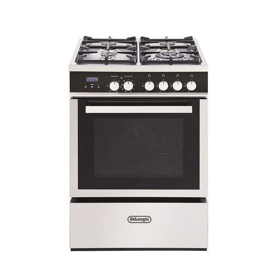
- Page 1 D E’ LO N G HI C OO KIN G INSTALLATION and SERVICE INSTRUCTIONS USE and CARE INSTRUCTIONS D EF6 08GW D UA L F U EL C OO K ER distributed by DeLonghi Australia Pty Ltd DeLonghi New Zealand Ltd...
-
Page 3: Product Label
Dear Customer, Thank you for having purchased and given your preferen- ce to our product. The safety precautions and recommendations reported below are for your own safety and that of others. They will also provide a means by which to make full use of the fea- tures offered by your appliance. -
Page 4: First Use Of The Oven
Important: This appliance is designed and manufactured solely for the coo- king of domestic (household) food and is not suitable for any non domestic application and therefore should not be used in a com- mercial environment. The appliance guarantee will be void if the appliance is used within a non domestic environment i.e. -
Page 5: Important Precautions And Recommendations
IMPORTANT PRECAUTIONS AND RECOMMENDATIONS After having unpacked the appliance, check to ensure that it is not damaged and that the oven door closes correctly. In case of doubt, do not use it and consult your supplier or a professionally qualified technician. - Page 6 However special care should be taken around the rear or the underneath of the appliance as these areas are not designed or intended to be touched and may contain sharp or rough edges, that may cause injury. ■ Do not line the oven walls with aluminium foil. Do not place ba- king trays or the drip tray on the base of the oven chamber.
-
Page 7: Installation
INSTALLATION CAUTION: ■ This appliance must be installed in accordance with these installation instructions. This appliance shall only be serviced by authorized personnel. ■ ■ This appliance is to be installed only by an authorised person in compliance with the current electrical regulations and in observation of the instructions supplied by the manufacturer. - Page 8 CLEARANCES Installation clearances and protection of combustible surfaces shall comply with the current local regulations eg. AS5601 / NZS5261 Gas Installations code. Installation shall comply with the dimension in Fig. 1 bearing in mind that. Overhead Clearances In no case shall the clearances between the highest part of the cooker be less than 600 mm or for an overhead exhaust fan 750 mm.
-
Page 9: Levelling The Cooker
LEVELLING THE COOKER The cooker is equipped with 4 levelling feet and may be levelled by screwing or unscrewing the feet with a spanner (fig. 3). It is important to observe the prescriptions of figures 4a, 4b. Figure 2 Figure 3 Figure 4b Supplied with the cooker Figure 4a... - Page 10 ANTI-TILT BRACKET Dotted line showing the position of Figure 5a the cooker when installed Important! To restrain the appliance and prevent it tipping accidentally, fit a bracket to its rear to fix it securely to the wall. Make sure you also fit the supplied lock pin to the anti-tilt bracket.
-
Page 11: Gas Supply
GAS SUPPLY ■ The connection must be performed by an authorised person according to the relevant standards. ■ Before connecting the appliance to the gas main, mount the brass conical adaptor onto the gas inlet pipe, upon which the gasket has been placed (figs. 6a - 6b). Conical adaptor and gasket are supplied with the appliance (packed with conversion kit for use with Natural gas or ULPG). - Page 12 INSTALLATION WITH A FLEXIBLE HOSE ASSEMBLY ■ If this appliance has to be installed with a hose assembly, the installer shall refer to the network operator or gas supplier for confirmation of the gas type, if in doubt. ■ When used with a flexible hose, the connector on the wall should be between 450 mm to 500 mm from the floor and 200 mm to 300 mm from the left-hand side of the appliance as viewed from the front.
- Page 13 Customer Service Centre should be called to obtain the nearest authorized Delonghi Service Agent. CONVERSION PROCEDURE (TO CONVERT TO NATURAL GAS OR TO ULPG) REPLACING THE INJECTORS This appliance is suitable for use with Natural gas or ULPG (check the “gas type”...
- Page 14 IMPORTANT ■ If the cooker is suitable for use with Natural gas and must be converted for use with ULPG, before connecting to gas main remove the appliance gas regulator and replace with test point adaptor (see figs. 6a - 6b) ■...
-
Page 15: Lubrication Of The Gas Taps
TABLE FOR THE CHOICE OF THE INJECTORS Natural gas ULPG Test Point Pressure [kPa] 2.75 Injector Injector BURNER Orifice Dia. Consumption Orifice Dia. Consumption [mm] [MJ/h] [mm] [MJ/h] Auxiliary (A) 0.85 3.60 0.53 3.60 Semi-rapid (SR) 1.12 6.30 0.70 6.30 Triple ring (TR) 1.60 12.70... - Page 16 USE AND CARE CAUTION: ■ This appliance must be used only for the task it has explicitly been designed for, that is for domestic cooking of foodstuffs. Any other form of usage is to be considered as inappropriate and therefore dangerous. ■...
-
Page 17: Grease Filter
GREASE FILTER Figure 14 ■ A special screen is provided at the back of the oven to catch grease par- ticles, mainly when meat is being roa- sted (fig. 14). ■ Clean the filter after any cooking! The grease filter can be removed for cleaning and should be washed regu- larly in hot soapy water (fig. -
Page 18: Control Panel
CONTROL PANEL Figure 15 MODE Controls description Front right burner control knob Rear right burner control knob Rear left burner control knob Front left burner control knob Multifunction oven function selector control knob Multifunction oven temperature control knob Clock and timer with “touch control” keys Pilot lamp Oven temperature indicator light Please note:... - Page 19 GAS HOB Figure 16 GAS BURNERS Natural Gas ULPG MJ/h MJ/h 1. Auxiliary burner (A) 2. Semi-rapid burner (SR) 3. Semi-rapid burner (SR) 4. Triple ring burner (TR) 12.7 11.9...
- Page 20 ■ If the flame is still not correct, turn the burner off and call our Customer Service center for your nearest Authorized Delonghi Service Agent. ■ In the case of a mains failure light the burner with a match or lighted taper.
- Page 21 CHOICE OF BURNER The burner must be chosen according to the diameter of the pans and energy required. For optimum efficiency uso a wok or pan no smaller than 230 mm diameter. Figure 18 do not use pans with concave or convex bases Burners Pan diameter Auxiliary...
- Page 22 CORRECT USE OF TRIPLE-RING BURNER ■ The flat-bottomed pans are to be placed directly onto the pan-support. ■ To use the WOK, you must place the wok stand in the CORRECT position as shown in figs. 20 - 21. IMPORTANT The special grille for wok pans (fig.
-
Page 23: Cooking With Multifunction Oven
COOKING WITH MULTIFUNCTION OVEN OPERATING PRINCIPLES Attention: The oven door becomes Heating and cooking in the MULTIFUN- very hot during operation. CTION oven are obtained in the following Keep children away. ways: a. by normal convection GENERAL FEATURES The heat is produced by the upper and lower heating elements. -
Page 24: Thermostat Knob
Figure 22 THERMOSTAT KNOB To turn on the heating elements of the oven, set function selector knob to the required po- sition and the thermostat knob to the desired temperature. To set the temperature, turn the thermostat control knob indicator mark to the required temperature. -
Page 25: Defrosting Frozen Foods
GRILLING The infra-red heating element is switched on. The heat is diffused by radiation. Use with the oven door closed and the thermostat knob must be regulated between 50°C and 200°C maximum. For correct use see chapter “USE OF THE GRILL”. Always grill with the oven door closed. -
Page 26: Cooking Advice
MAINTAINING TEMPERATURE AFTER COOKING OR SLOWLY HEATING FOODS The upper element and the circular element connected in series, are switched on; also the fan is on. The heat is diffused by forced convection with the most heat being produced by the upper ele- ment. -
Page 27: Use Of The Grill
SIMULTANEOUS COOKING OF DIFFERENT FOODS The MULTIFUNCTION oven set on position gives simultaneous heterogeneous cooking of different foods. Different foods such as fish, cake and meat can be cooked toge- ther without mixing the smells and flavours. This is possible since the fats and vapors are oxidized while passing through the electrical element and therefore are not deposited onto the foods. - Page 28 RECOMMENDED COOKING TEMPERATURE Shelf Cooking Food °C °F Mark Position* Time (approx) CAKES Victoria sandwich 2 or 3 20-25 mins Small cakes/buns 1 and 2 15-20 mins Maidera cake 2 or 3 20 mins Fruit cake hours Rich fruit cake 3 or 4 hours Scones...
-
Page 29: Clock And Timer With " Touch Control" Keys
CLOCK AND TIMER WITH “ TOUCH CONTROL” KEYS Keys: Touched simultaneously (for more than 2 seconds): ■ setting the clock; ■ setting the timer vo- lume touching once, along with the “MODE” key); ■ to cancel automatic cooking at any time. Function selection (tou- Figure 23 ched for more than 2 se-... -
Page 30: Setting The Clock
“TOUCH-CONTROL” KEYS The “touch-control” keys shall be operated by the fingers (just by touching the key). When using touch controls it is best to use the ball of your finger rather than the tip. The keys are automatically deactivated: ■ 8 seconds after the last selection;... -
Page 31: Automatic Cooking
SETTING THE TIMER VOLUME You can select from three volume levels. ■ Touch the “ ” and “ ” keys simultaneously for more than 2 seconds. ■ Touch the “ MODE ” key; you can read on the display the current timer volume (“ton1”, “ton2”... -
Page 32: Cleaning And Maintenance
CLEANING AND MAINTENANCE Maintenance Period Description Daily ■ Clean gas cooktop as per instructions below ■ Remove burner caps, burner rings & base and clean using non abrasive detergent & rinse in cold water & dry thorou- ghly Monthly before replacing back on hob Monthly ■... -
Page 33: Glass Control Panel
GAS TAPS If the gas taps are not working properly, call our Customer Service Centre to obtain the nearest Authorized Delonghi Service Agent. GRILL HEATING ELEMENT ■ The heating element is self-cleaning and does not require maintenance. - Page 34 REPLACING THE HALOGEN OVEN LIGHT WARNING: Ensure the appliance is switched off before replacing the lamp to avoid the possibility of electric shock. ■ Let the oven cavity and the heating elements to cool down. WRONG ■ Switch off the electrical supply. ■...
- Page 35 Figure 25a Figure 25b Figure 26a Figure 26c Figure 26b...
-
Page 36: Storage Drawer
STORAGE DRAWER ■ The drawer comes out like a normal drawer. A safety catch stops it from sliding out. ■ The handle is concealed at bottom of front panel. ■ To remove the drawer proceed as per figure 28. ■ To replace the drawer repeat the steps in reverse order. - Page 37 REMOVING AND REPLACING THE INNER DOOR GLASS PANE FOR CLEANING If you wish to clean the inner glass of the door, make sure you follow the precautions and instructions very carefully. Replacing the glass pane and the door incorrectly may result in damage to the appliance and may void your warranty.
-
Page 38: Removing The Oven Door
REMOVING THE OVEN DOOR The oven door can easily be removed as follows: ■ Open the door to the full extent (fig. 30a). ■ Open the lever “A” completely on the left and right hinges (fig. 30b). ■ Hold the door as shown in fig. 29. ■... - Page 39 CLEANING THE PANES OF GLASS The oven door is fitted with no. 2 panes: ■ no. 1 outside; ■ no. 1 inner. To clean the panes on both sides it is ne- cessary to remove the inner pane as fol- lows.
- Page 40 REPLACING THE INNER PANE OF GLASS Make sure the door is locked open (see fig. 30c). Replace the inner pane: ■ Check that the four rubber pads are in place (“D” in Fig. 32a). Figure 32a ■ Check that you are holding the pane the correct way.
-
Page 41: Service And Maintenance
SERVICING THE APPLIANCE Service may be obtained by contacting our Customer Service Centre to locate the nearest Authorised Delonghi Service Agent: Servicing shall be carried out only by authorized personnel. The appliance shall not be modified. -
Page 42: Electric Diagram
ELECTRIC DIAGRAM Figure 33... - Page 43 ELECTRIC DIAGRAM KEY Oven switch Oven thermostat Safety thermostat Oven lamp Oven programmer Cooling fan motor Oven fan motor Oven top element Oven grill element Oven bottom element Oven circular element Thermal overload Thermostat pilot lamp Ignition switches group Ignition coil Terminal block Earth connection...
- Page 44 .au ww w.de lo nghi.co .nz...