
Related Manuals for DeLonghi DEL6038D


Summary of Contents for DeLonghi DEL6038D
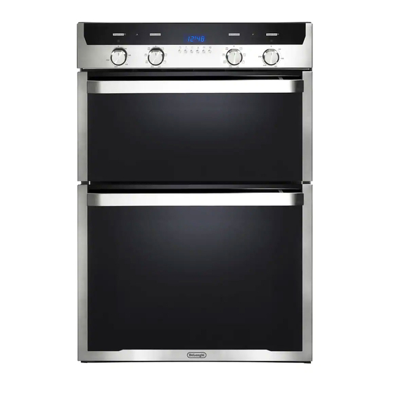
- Page 1 D E’ LO N G HI C OO KIN G INSTALLATION and SERVICE INSTRUCTIONS USE and CARE INSTRUCTIONS D EL603 8 D B UI LT- I N DOUBL E OVEN distributed by DeLonghi Australia Pty Ltd DeLonghi New Zealand Ltd...
-
Page 2: Product Label
Dear Customer, Thank you for having purchased and given your preference to our product. The safety precautions and recommendations reported below are for your own safety and that of others. They will also provide a means by which to make full use of the features offered by your appliance. -
Page 3: Important Safety Precautions And Recommendations
IMPORTANT SAFETY PRECAUTIONS AND RECOMMENDATIONS IMPORTANT: This appliance is designed and manufactured solely for the cooking of domestic (household) food and is not suitable for any non domestic application and therefore should not be used in a commercial environment. The appliance guarantee will be void if the appliance is used within a non domestic environment i.e. - Page 4 ■ Do not use a steam cleaner because the moisture can get into the appliance therefore making it unsafe. ■ Do not touch the appliance with wet or damp hands (or feet). ■ Do not use the appliance whilst in bare feet. ■...
- Page 5 ■ WARNING: When correctly installed, your product meets all safety requirements laid down for this type of product category. However special care should be taken around the rear or the underneath of the appliance as these areas are not designed or intended to be touched and may contain sharp or rough edges, that may cause injury.
-
Page 6: Installation
■ Do not seal the double oven into the cabinetry with silicone or glue; this makes future servicing difficult. Delonghi will not cover the costs of removing the double oven, or of damage caused by this removal. The walls surrounding the double oven must be made of heat-resistant material. - Page 7 Dimensions Oven Housing (mm) Height Width Depth 555 min. Figure 1...
- Page 8 FIXING THE DOUBLE OVEN Introduce the double oven into the furniture opening and fix it with 8 screws (not supplied) as figure 2. It is essential that the double oven rests on a surface which will support its weight, as the screw fixing is only complementary. Note It is essential that when installing your double oven adequate air circulation is allowed for within the installation.
- Page 9 Figure 3 OVEN DOOR LOWER TRIM AIR FLOW IMPORTANT: Please take extra care not to damage the lower trim of the double oven. Ensure the double oven sits on wooden blocks or similar supports when it is removed from the carton as shown in above diagram.
-
Page 10: Electrical Requirements
ELECTRICAL REQUIREMENTS ■ The appliance must be connected to the mains checking that the voltage corresponds to the value given in the rating plate and that the electrical cable sections can withstand the load specified on the plate. ■ A suitable isolating switch providing full disconnection from the mains power supply shall be incorporated in the permanent wiring, mounted and positioned to comply with the local wiring rules and regulations. - Page 11 – The wire which is coloured GREEN AND YELLOW must be connected to terminal which is marked with the letter “E” or by the Earth symbol or coloured GREEN or GREEN AND YELLOW. – The wire which is coloured BLUE must be connected to the terminal which is marked with the letter “N”...
-
Page 12: Wiring Diagram
WIRING DIAGRAM Figure 6... - Page 13 ELECTRIC DIAGRAM KEY Cooling fan motor Thermal overload Terminal block Earth connection MAIN OVEN Oven switch Oven thermostat LF/LF1 Oven lamps Thermostat pilot lamp Oven programmer Oven fan motor Oven top element Oven grill element Oven bottom element CIR1 Oven circular element TOP OVEN Oven switch Oven thermostat...
-
Page 14: Using The Ovens For The First Time
USE AND CARE CAUTION: ■ This appliance must be used only for the task it has explicitly been designed for, that is for domestic cooking of foodstuffs. Any other form of usage is to be considered as inappropriate and therefore dangerous. ■... -
Page 15: Bottom Main Oven
TOP OVEN BOTTOM MAIN OVEN Figure 7a Figure 7b Figure 8a Figure 8b Stop notch Guard rail Stop notch Guard rail Stop notch Stop notch... - Page 16 GREASE FILTER Figure 9 ■ special screen provided at the back of the ovens to catch grease particles, mainly when meat is being roasted (fig. ■ Clean the filters after any cooking! The grease filters can be removed for cleaning and should be washed regularly in hot soapy water (fig.
- Page 17 TELESCOPIC SLIDING SHELF SUPPORTS The telescopic sliding shelf supports make it safer and easier to insert and remove the oven shelves and trays. They stop when they are pulled out to the maximum position. Important! When fitting the sliding shelf supports, make sure that you fit: ■...
- Page 18 To remove the telescopic sliding shelf supports: ■ Remove the side racks and the catalytic liners by unscrewing the fixing screws (fig. 13). ■ Lay down the telescopic sliding shelf support and side racks, with the telescopic sliding shelf support underneath. ■...
-
Page 19: Control Panel
CONTROL PANEL Figure 15 Controls description Oven temperature control knob (Top oven) Function selector control knob (Top oven) Digital electronic programmer (Bottom main oven only) Function selector control knob (Bottom main oven) Oven temperature control knob (Bottom main oven) Pilot lamps Main oven temperature indicator light Line pilot light (Main oven) Line pilot light (Top oven) -
Page 20: General Features
COOKING WITH MULTIFUNCTION OVENS OPERATING PRINCIPLES Attention: The oven door becomes Heating and cooking in the very hot during operation. MULTIFUNCTION oven are Keep children away. obtained in the following ways: a. by normal convection GENERAL FEATURES The heat is produced by the upper and lower heating elements. -
Page 21: Thermostat Knob
Figure 16 Figure 17 THERMOSTAT KNOB To turn on the heating elements of the oven, set function selector knob to the required position and the thermostat knob to the desired temperature. To set the temperature, turn the thermostat control knob indicator mark to the required temperature. -
Page 22: Defrosting Frozen Foods
GRILLING The infra-red heating element is switched on. The heat is diffused by radiation. Use with the oven door closed and the thermostat knob must be regulated between 50°C and 225°C maximum. For correct use see chapter “USE OF THE GRILL”. Always grill with the oven door closed. -
Page 23: Cooking Advice
MAINTAINING TEMPERATURE AFTER COOKING OR SLOWLY HEATING FOODS The upper element and the circular element connected in series, are switched on; also the fan is on. The heat is diffused by forced convection with the most heat being produced by the upper element. -
Page 24: Use Of The Grill
SIMULTANEOUS COOKING OF DIFFERENT FOODS The MULTIFUNCTION oven set on position gives simultaneous heterogeneous cooking of different foods. Different foods such as fish, cake and meat can be cooked together without mixing the smells and flavours. This is possible since the fats and vapors are oxidized while passing through the electrical element and therefore are not deposited onto the foods. - Page 25 RECOMMENDED COOKING TEMPERATURE Shelf Cooking Food °C °F Mark Position* Time (approx) CAKES Victoria sandwich 2 or 3 20-25 mins Small cakes/buns 1 and 2 15-20 mins Maidera cake 2 or 3 20 mins Fruit cake hours Rich fruit cake 3 or 4 hours Scones...
- Page 26 ELECTRONIC CLOCK/PROGRAMMER (Bottom main oven only) The electronic clock/programmer is a device which groups together the following functions: • 24 hours clock with illuminated display. • Timer (up to 23 hours and 59 minutes). • Program for automatic oven cooking. •...
-
Page 27: Electronic Timer
ELECTRONIC CLOCK ELECTRONIC TIMER (fig. 19) The programmer is equipped with an The timer program consists only of a electronic clock with illuminated numbers buzzer which may be set for a maximum which indicates hours and minutes. period of 23 hours and 59 minutes. Upon immediate connection of the oven or If the AUTO symbol is flashing push the after a power cut, three zeros will flash on... -
Page 28: Automatic Oven Cooking
AUTOMATIC OVEN COOKING Set the temperature and the cooking program by using the switch and To cook food automatically in the oven, it is thermostat knobs of the oven (see necessary to: specific chapters). Set the length of the cooking period. oven programmed Set the end of the cooking time. -
Page 29: Semi-Automatic Cooking
SEMI-AUTOMATIC COOKING At the end of the cooking time the oven will turn off automatically, the symbol This is used to automatically switch off the will turn off, AUTO will flash and a buzzer oven after the desired cooking time has will be sound, which can be turned off by elapsed. -
Page 30: Cleaning And Maintenance
CLEANING AND MAINTENANCE GENERAL ADVICE Before you begin cleaning, you must ensure that the appliance is switched off ■ and disconnected from the electrical power supply. ■ It is advisable to clean when the appliance is cold and especially when cleaning the enamelled parts. -
Page 31: Grease Filter
INSIDE OF OVENS The oven should always be cleaned after use when it has cooled down. The cavity should be cleaned using a mild detergent solution and warm water. Suitable proprietary chemical cleaners may be used after first consulting with the manufacturers recommendations and testing a small sample of the oven cavity. -
Page 32: Replacing The Oven Lights
REPLACING THE OVEN LIGHTS WARNING: Ensure the appliance is switched off before replacing the lamp/s to avoid the possibility of electric shock. ■ Let the oven cavity and the heating elements to cool down. ■ Switch off the electrical supply. LEFT LAMP (BOTTOM MAIN OVEN ONLY) ■... - Page 33 REMOVING AND REPLACING THE INNER DOOR GLASS PANES FOR CLEANING If you wish to clean the inner panes of glass of the doors, make sure you follow the precautions and instructions very carefully. Replacing the glass panes and the doors incorrectly may result in damage to the appliance and may void your warranty.
-
Page 34: Removing The Oven Doors
REMOVING THE OVEN DOORS The oven doors can easily be removed as follows: ■ Open the door to the full extent (fig. 27). ■ Open the lever “A” completely on the left and right hinges (fig. 28). ■ Hold the door as shown in fig. 31. Figure 27 ■... - Page 35 TOP OVEN DOOR (WITH TWO PANES OF GLASS) CLEANING THE PANES OF GLASS The oven door is fitted with no. 2 panes: ■ no. 1 outside; ■ no. 1 inner. To clean all panes on both sides it is necessary to remove the inner pane as follows.
- Page 36 TOP OVEN DOOR - REPLACING THE INNER PANE OF GLASS Make sure the door is locked open (see fig. 29). Replace the inner pane: ■ Check that the four rubber pads are in place (“D” in fig. 34). Figure 34 ■...
- Page 37 BOTTOM OVEN DOOR (WITH THREE PANES OF GLASS) CLEANING THE PANES OF GLASS The oven door is fitted with no. 3 panes: ■ no. 1 outside; ■ no. 1 inner; ■ no. 1 in the middle. Figure 39 To clean all panes on both sides it is necessary to remove the inner and the middle panes as follows.
- Page 38 BOTTOM OVEN DOOR - REPLA- CING THE MIDDLE AND INNER PANES OF GLASS Make sure the door is locked open (see fig. 29). Replace the middle pane: ■ Check that the four rubber pads are in place (“M” in fig. 43). ■...
- Page 39 Replace the inner pane: ■ Check that the four rubber pads are in place (“D” in fig. 46). ■ Check that you are holding the pane the correct way. You should be able to read the wording on it as it faces you. ■...
-
Page 40: Service And Maintenance
The controls are switched on. Bottom oven only: none semi-automatic or automatic cooking program has been selected. Both the fuse and the mains fuse are intact. Should you still require assistance please contact our Customer Service Centre for your nearest Authorised Delonghi Service Agent. - Page 44 .au ww w.de lo nghi.co .nz...