Table of Contents
Advertisement
Advertisement
Table of Contents

Related Manuals for Invacare Electra


Summary of Contents for Invacare Electra
- Page 1 Invacare® Electra Scooter Service Manual...
-
Page 2: Service Manual
® Invacare Electra Service Manual ® How to get in touch with INVACARE If you have any questions, or need help, you can reach us using the following addresses and telephone numbers within Europe: Invacare® Deutschland GmbH Invacare® A/S Dehmer Str. 66 Sdr. -
Page 3: Table Of Contents
® Invacare Electra Service Manual Contents GENERAL INFORMATION TRANSPORT IMPORTANT SYMBOLS USED IN THIS MANUAL SAFETY INFORMATION Before working During work: After work: TOOL LIST LAYOUT OF COMPONENTS AND DISPLAYS AND CONTROLS MAINTENANCE PLAN TROUBLESHOOTING General Fault causes Fault and diagnosis codes 8.3.1... - Page 4 ® Invacare Electra Service Manual 9.4.2 Components involved: 9.4.3 Reassembly information for "replacing anti-tipper wheels Steering fork / front wheel 9.5.1 Components: 9.5.2 Components involved: 9.5.3 Preparation forreassembly 9.5.4 Reassembly sequence for "replacing steering head bearings / steering fork 9.5.5 Reassembly information for "replacing steering head bearings"...
- Page 5 ® Invacare Electra Service Manual 12.1 Charging of fully discharged batteries 12.2 Connecting the programming device 12.2.1 Preparation 12.2.2 Connecting the programming device As at: 15.04.02 Page 5...
-
Page 6: General Information
• We reserve the right to make any alterations on the grounds of technical improvements. 2 Transport If the Scooter or Scooter components need to be sent to INVACARE for major repairs, please observe the following information: • Pack the Scooter or its components so they cannot be damaged during transport. If possible, use the original packaging which the Scooter or its components were sent in. -
Page 7: Safety Information
® Invacare Electra Service Manual 4 Safety information 4.1 Before working Note: • Mark the current settings on the Scooter (seat, armrest, backrest etc.). This makes rebuilding the Scooter much easier. • Before disassembling electrical components, mark the plug connections corresponding to the cables This makes reassembly easier. -
Page 8: After Work
• flat-nosed pliers • pointed pliers • plumber's wrench • cable lug pliers • plastic hammer • wheel bearing puller • Multimeter with probes and various cable clips • drive wheel hub puller (available from INVACARE Service) Page 8 As at:15.04.02... -
Page 9: Layout Of Components And Displays And Controls
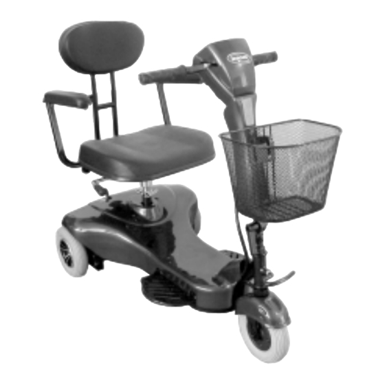
® Invacare Electra Service Manual 6 Layout of components and displays and controls The following illustrations show the general arrangement of the Electra Scooter's subassemblies, components and control elements. 1. Seat element with armrest and backrest "Electra Scooter" standard configuration 2. -
Page 10: Maintenance Plan
® Invacare Electra Service Manual 7 Maintenance plan Carry out an inspection on the Scooter using the maintenance plan. You can make this inspection easier by copying the maintenance plan and noting any defects found in the plan. Defec Item:... - Page 11 ® Invacare Electra Service Manual Defec Item: Checks Remedy Drive unit: Check functioning and smooth running of motor and gearbox Check motor clutch for push mode Replacing components chapt.: 9.6 page: 23 Check connection between drive unit and chassis for tight fit...
-
Page 12: Troubleshooting
® Invacare Electra Service Manual 8 Troubleshooting 8.1 General You can determine the reason for faults in the Scooter in drive mode, on the server motors or in the power supply by carrying out the following steps: Schritt 1: Limit fault causes as per table in chapter: 8.2 page: 12. -
Page 13: Fault And Diagnosis Codes
® Invacare Electra Service Manual 8.3 Fault and diagnosis codes Status display If there is an electrical fault, this is displayed by the fact that the power pilot light (11; status display) in the operating unit blinks. This displays an error code which allows an approximate fault diagnosis. -
Page 14: Maintenance And Repair
® Invacare Electra Service Manual 9 Maintenance and repair Seat unit Detail: Backrest Detail: Seat: 9.1.1 Components: Backrest and seat Item Qty. Description Item Qty. Description Seat S232, black Bottom backrest tube S232 3.01 3.07 Seat plate Knob, black 3.02 3.08... -
Page 15: Components: Seat Unit
® Invacare Electra Service Manual 9.1.2 Components: Seat unit Item Qty. Description Item Qty. Description Bolt, M6 X 30 Bolt, M6 X 16 3.05 3.20 3.08 Knob, black 3.21 Washer, M6 X 1 Nut M8, self-locking Nut, M6 with plastic cap 3.13... -
Page 16: Components Involved
® Invacare Electra Service Manual 9.1.3 Components involved Panelling (chapter: 9.3 page: 19 9.1.4 Reassembly information Before disassembling the seat unit, mark the height of the seat attachment (3.4), the backrest and the armrest width settings. 9.1.5 Reassembly information for "removing seat unit"“... -
Page 17: Steering Column
® Invacare Electra Service Manual Steering column Detail: connection to steering fork 9.2.1 Components: Item Qty. Description Item Qty. Description Handlebar S533 Steering cover, top 4.01 4.13 Handle, LH Drive lever 4.03 4.20 Handle, RH Steering cover, bottom 4.04 4.39... -
Page 18: Reassembly Information For "Removing Steering Column
® Invacare Electra Service Manual 9.2.3 Reassembly information for "removing steering column" Connecting plugs • Remove seat unit (see chapter9.1.5). • Carefully pull the chassis panelling upwards off the Velcro connectors. • Interrupt power supply. Battery cable (1). • Disconnect the power supply connecting plug at the operating unit (2) and the connecting plug at the controller (3). -
Page 19: Panelling
Qty. Description Velcro loop strip 50 X 25 Reflector 1.11 2.03 Snap buckle Reflector, red 1.18 2.04 Panelling "ELECTRA" sticker 2.01 2.05 2.02 "INVACARE" sticker 2.06 Velcro strap 50 X 25 "Battery wiring circuit" sticker 2.07 9.3.2 Components involved: Seat unit (chapter: 9.1 page: 14) As at: 15.04.02... -
Page 20: Chassis
® Invacare Electra Service Manual Chassis Detail: antitipper (1.2 / 1.3) 9.4.1 Components: Item Qty. Description Item Qty. Description Chassis unit, complete Fixing for anti-tipper wheel 1.01 1.19 1.02 Fixing for rear panelling 1.20 Anti-tipper wheel, 40 mm Bolt, M6 X 30 Bolt, M6 X 36,5 1.15... -
Page 21: Steering Fork / Front Wheel
® Invacare Electra Service Manual Steering fork / front wheel 9.5.1 Components: Item Qty. Description Front wheel fork 5.01 5.02 Wheel rim 200 X 50 5H, black Wheel rim 200 X 50 6H, black 5.03 5.04 Bolt, M6 X 30 Nut M6 self-locking 5.05... -
Page 22: Reassembly Sequence For "Replacing Steering Head Bearings / Steering Fork
® Invacare Electra Service Manual 9.5.4 Reassembly sequence for "replacing steering head bearings / Replacing the steering steering fork head bearings • Remove the steering column (chapter: 9.2.3 page: 18). • Remove the steering fork and replace the steering head bearings. -
Page 23: Drive Unit
® Invacare Electra Service Manual Drive unit 9.6.1 Components: Item Qty. Description Item Qty. Description Drive unit Bolt, M8 X 55 5.23 5.29 5.24 Reduction gears 5.30 Nut M8, self-locking 5.25 Rubber bumper 5.31 Washer, M8 X 1,6 5.26 5.32... -
Page 24: Preparation Forreassembly
® Invacare Electra Service Manual 9.6.3 Preparation for reassembly Battery plug • Remove seat unit (see chapter9.1.5). • Remove clamp and seat tube (see chapter 9.1.6) • Carefully pull the chassis panelling upwards off the Velcro connectors. • Interrupt power supply. Battery cable (1). -
Page 25: Drive Wheels
® Invacare Electra Service Manual Drive wheels 9.7.1 Components: Item Qty. Description Item Qty. Description Rear wheel unit Nut M8, self-locking 5.22 5.18 Wheel rim (B) 7" Nut M8, self-locking 5.19 Wheel rim rear wheel Washer, M8 5.20 Tyre 200 X 50, puncture-proof 5.21... -
Page 26: Service And Repair - Electrics And Electronics
® Invacare Electra Service Manual 10 Service and repair - electrics and electronics 10.1 Batteries / main fuse / controller Detail: Cable clamp position 10.1.1 Components: Item Qty. Description Item Qty. Description Electronics, RHINO DS 72 K01 Battery, complete 1.07 1.08... -
Page 27: Preparations Forreassembly
® Invacare Electra Service Manual 10.1.3 Preparations forreassembly • Remove seat unit (see chapter9.1.5). • Remove clamp and seat tube (see chapter 9.1.6) • Carefully pull the chassis panelling upwards off the Velcro connectors. Battery plug 10.1.4 Reassembly information for "removing the battery pack"... -
Page 28: Operating Unit
® Invacare Electra Service Manual 10.2 Operating unit Detail: Drive lever 10.2.1 Components: Item Qty. Description Item Qty. Description Main wiring harness "INVACARE" sticker 4.02 4.48 Steering cover, top 4.13 4.49 Wiring harness, steering PCB top Sticker S532 Wiring harness, steering PCB 4.14... -
Page 29: Preparations Forreassembly
® Invacare Electra Service Manual >Battery charge display Drive lever 4.17 4.20 "ON/OFF" pilot light Nut M3, self-locking 4.18 4.21 4.33 Buzzer 4.22 Drive lever rubber Nut M3, self-locking 4.34 4.23 4.35 Spacer, 6,4 X 4 X 19,47 4.24 Restoring spring... -
Page 30: Reassembly Information For "Replacing The Drive Regulator Potentiometer
® Invacare Electra Service Manual • Open the operating unit Open the operating unit. Two Phillips screws (6 + 7). • Disconnect the wiring harness connecting plug (8) in the operating unit. • Replace the wiring harness. 10.2.4 Reassembly information for "replacing the drive regulator Replacing the potentiometer"... -
Page 31: Test Sequences - Electrics / Electronics
® Invacare Electra Service Manual 11 Test sequences - electrics / electronics 11.1 Checking the battery voltage CAUTION: • Risk of short circuit.Take care with tools.Do not bridge battery terminals • Only use the gel batteries indicated in the spare parts catalogue as replacement batteries. -
Page 32: Check Drive Motor
® Invacare Electra Service Manual 11.1.3 Testing the individual voltage of the batteries Test the individual voltage U on the batteries that have been taken out by means of a Multimeter (measuring range 50 V / 25 V DC (see chapter 10.1 page: 26). -
Page 33: Magnet Brake
® Invacare Electra Service Manual 11.2.2 Magnet brake Drive unit connector plug • Remove drive unit panelling (see chapter 9.3 page: 19). • Remove the drive unit connecting plug at the controller (3). • Engage motors. • Set the Multimeter to resistance measuring. -
Page 34: Checking Power Supply To Operating Unit
® Invacare Electra Service Manual 11.3 Checking power supply to operating unit Connector plug in operating unit • Open operating unit (see chapter 10.2.3 page: 29). • Disconnect the wiring harness connector plugs (8) from the controller in the operating unit. -
Page 35: Appendix
Do not fully charge batteries using an unregulated charger. • Put batteries back into the vehicle. • Fully charge battery using the Invacare charger via the Scooter charging socket . The charging procedure should last for at least 48 hours. 12.2 Connecting the programming device 12.2.1 Preparation •... -
Page 36: Connecting The Programming Device
® Invacare Electra Service Manual 12.2.2 Connecting the programming device Remove the cover cap • Switch off the Scooter. • Remove the chassis panelling (see chapter 9.3 page: 19). • Remove the cover cap (1) next to the remote plug on the controller.