
Related Manuals for Invacare Comet Series


Summary of Contents for Invacare Comet Series
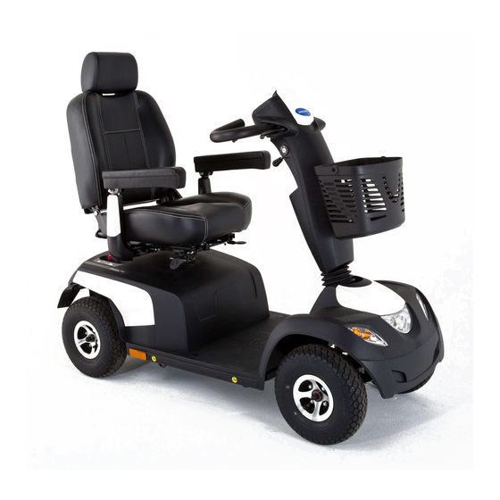
- Page 1 Invacare® Comet Series ALPINE+ ULTRA Comet , Comet , Comet en Scooter Service Manual DEALER: Keep this manual. The procedures in this manual MUST be performed by a qualified technician.
- Page 2 All rights reserved. Republication, duplication or modification in whole or in part is prohibited without prior written permission from Invacare. Trademarks are identified by ™ and ®. All trademarks are owned by or licensed to Invacare Corporation or its subsidiaries unless otherwise noted.
-
Page 3: Table Of Contents
Contents 1 General ......... 4 1.1 General information . -
Page 4: General
• Spare parts MUST match original Invacare parts. Only in minor or slight injury if it is not avoided. use spare parts which have been approved by Invacare. • We reserve the right to make any alterations on the IMPORTANT grounds of technical improvements. -
Page 5: Safety
Safety 2 Safety CAUTION! Injury hazard if the vehicle starts moving unintentionally during repair work 2.1 Safety and fitting instructions – Switch the power supply off (ON/OFF key). – Engage the drive. These safety instructions are intended to prevent accidents –... - Page 6 To release the dealers. connecting plugs the safety devices must be pressed – Invacare supplies all mobility devices with a in. When reassembling ensure that these safety standard drive program ex-works. Invacare can devices are correctly engaged.
-
Page 7: Hygiene
Use saturated Cleaning and reconditioning disinfectant wipes disinfection and clean* the device surface. *Invacare uses detergent "Nücosept special" 1.5% in water ml/ml Disinfection tools • One way wipes (fleece) • Brushes to clean difficult to access areas Further information For more information contact your Invacare Service department. -
Page 8: Service
Comet 4.2 Troubleshooting 4 Service 4.2.1 Operational faults 4.1 General safety information on installation Proceed as follows if you have any problems: work 1. First assess the possible cause of the problem using the Risk of damage to mobility device following table. -
Page 9: Error Codes And Diagnostic Codes
Ensure that the disengaging lever is in the engaged position. • There is a defect in the braking coil or in the cabling. Check the magnetic brake and cabling for open or short-circuited circuitry. Contact your Invacare provider. No neutral position Stops driving •... -
Page 10: Service Plan (1X Annually)
Comet Thread Tightening torque in Thread Tightening torque in Nm ±10% Nm ±10% 10 Nm 80 Nm 25 Nm 120 Nm 49 Nm 180 Nm 4.4 Service plan (1x annually) Component Notes Check Remedy Seat Check welded Tighten screws, seams, fixings and replace parts if upholstery damaged... -
Page 11: Controls
Service Component Notes Check Remedy Drive controls Check status display Evaluate flash code (flashing) Check fixing Tighten or replace fixing Check cable, Replace cable, connecting plug connecting plug Check drive lever Replace drive lever function Check power supply Replace cable, connecting plug or console Drive program... -
Page 12: Replacing Circuit Board
Comet 1. Unplug battery connector. Remove screws A below operating console. Remove operating console as described in chapter 4.5.1 6. Remove operating console and fold upwards. Replacing operating console, page 11. 7. Remove screws C on drive lever B and remove drive 3. -
Page 13: Replacing Lifter/Lifter Controls
Service Remove top shroud A from steering column B. Fig. 4-5 Fig. 4-6 Reconnect potentiometer plug A with operating console. Connect potentiometer A and drive lever mounting B: Remove screws A below operating console. • Tighten screw C. 6. Remove operating console and fold upwards. 7. -
Page 14: Replacing Power Module
– Changes to drive program may only be carried out by trained Invacare® specialist providers. Replacing lifter controls – Invacare® can only give a warranty for safe mobility device driving behaviour - especially tipping stability - for unaltered standard drive programs. -
Page 15: Setup Settings
Service 4.5.6 Setup settings Operating console (LED version) Arrangement Disconnect battery cable (1). 6. Remove rear wheel fixing screws. 7. Remove rear wheels. 8. Remove drive unit. See 4.10.1 Replacing drive unit, page 9. Remove screws (1) on power module (2). •... - Page 16 Comet Status display Reduced driving range. Battery capacity: Recharge the batteries at the end <25% of your journey. Battery reserve = severely Battery capacity: restricted driving range. <20% Recharge batteries immediately! A Speed indication B Fault indication C Curve control indication Battery capacity D Maintenance indication >80%...
- Page 17 Service 1. Turn key to switch mobility device off. Press key to increase value. Press and hold keys. 3. Turn key to switch mobility device on. Press key to decrease value. Mobility device enters setup mode after two seconds. Press key to save and enter next page. Enter next display with Setting battery gauge key.
-
Page 18: Shrouds
Comet AGM battery Gel battery (1) big size (2) small (3) small size (4) big size batteries (> size batteries batteries (< batteries (> 50 A) (< 50 A, 50 A) 50 A) default) Press key to increase value. Press key to change settings. 2. -
Page 19: Lighting Unit
Service 1. Remove rear shroud. See 4.6.1 Removing shroud, page Remove headlight. Remove four caps A. 8. Remove screws (1) on headlight glass. 3. Loosen and remove screws B. 9. Remove headlight glass. 4. Take off front shroud. 10. Replace bulb (2) in headlight. 5. -
Page 20: Replacing Center Brake Light
Comet Remove screws (3) on indicator glass. 7. Remove indicator glass. Disconnect plug (4). 8. Loosen screws (4) on orange-colored cap (5) and remove cap. 9. Replace lightbulb. 10. Install parts in reverse order. 11. Test functions. 4.7.3 Replacing center brake light CAUTION! Risk of burns if power cable is shorted –... -
Page 21: Wheels
Service • Phillips screwdriver 1. Remove seat. 2. Remove shroud. Remove rear light glass (1). 10. Replace lightbulbs (2). 11. Install parts in reverse order. 12. Test function. Disconnect battery cable A. 4.8 Wheels 4.8.1 Replacing wheel suspension CAUTION! Risk of accident Accidental rolling can lead to accidents. -
Page 22: Replacing Shock Absorber
Comet Replacing rear shock absorber Loosen wheel suspension screw (1). 6. Loosen screw (2). 7. Replace wheel suspension. 8. Install parts in reverse order. Remove top screw (1) on shock absorber (2). 2. Remove both screws (4) from motor bracket (5). Tighten screw (1) to 25 Nm. -
Page 23: Replacing Steering Column
Service 6. Remove and replace swing arm. Loosen and remove screw A that attaches swing arm to chassis on left and right side of the mobility device. Install parts in reverse order. When reinstalling, tighten screw A to 15 Nm. 4.8.4 Replacing steering column CAUTION! Risk of accident... -
Page 24: Replacing Front Wheel Suspension 4-Wheel
Comet Replacing steering column Remove screws A on front steering column shroud. 12. Remove front steering column shroud. 13. Loosen brake cable. See 4.9.1 Replacing hand brakes, Remove drive lever screws C. page 26. 2. Remove drive lever B. 3. Loosen and remove screwsA on operating console. 4. -
Page 25: Replacing And Adjusting Central Rear Shock
Wooden block • 45/50 hook wrench • Vise To adjust central rear shock absorber to user weight, Invacare recommends removing central rear shock absorber. Removing Loosen screws on cross members B on left and right Fig. 4-10 side. 1. Remove wheel (see user manual). -
Page 26: Repairing Tire Punctures
– Always use new bolts with an undamaged Problems when removing wheel? coating. – It may be necessary to use a special tool. Ask your Invacare provider to help you. 4.9 Brakes Repairing flat tire 4.9.1 Replacing hand brakes •... -
Page 27: Replacing Brake Cable
Service 4.9.2 Replacing brake cable When disassembling, note the position of small parts such as screws and washers. Put small parts down so CAUTION! that they can be reassembled in the right sequence. Risk of accident Accidental rolling can lead to accidents. •... -
Page 28: Replacing Curve Control Device
Comet 3. Install parts of steering link and/or coupling rod in reverse order. 4. Test all functions (trial run). 4.9.4 Replacing curve control device CAUTION! Risk of accident Accidental rolling can lead to accidents. – Secure mobility device against rolling away. When disassembling, note the position of small parts such as screws and washers. -
Page 29: Drive Components
Service 6. Remove screw B that fixes shroud between front 3. Install parts in reverse order. wheels. 4. Check functions (trial run). 4.10 Drive components 4.10.1 Replacing drive unit CAUTION! Risk of accident When parking mobility device on antitippers it is no longer slowed by motor brake. - Page 30 Comet Disconnect plugs from power module. • Disconnect motor plug. • Disconnect plug for electromagnetic brake. • Disconnect speedometer plug. Remove screws (1) on disengaging lever (2). 15. Remove disengaging lever (2). 16. Place supporting wooden block under swing arm. Replacing drive motor Remove screws A on mud guard.
-
Page 31: Replacing Carbon Brushes
Service Installation 4. Loosen and remove all four plastic caps B. Note the fixing position and location of the 1. Install parts in reverse order. carbon brushes. Used carbon brushes need to the refitted exactly in the same position from which they were taken in order to guarantee optimum contact to the collector. -
Page 32: Replacing Seat Support Tube
• Covers: Storage cover (Full scooter cover), Seat Cover (Rain & Dirt protection) The installation instructions for additional accessories are available at your Invacare® provider or directly from Invacare®. Firmly tighten securing bolt of seat support tube. 14. Reposition seat. - Page 33 Notes...
- Page 34 Notes...
- Page 35 Notes...
- Page 36 Invacare representatives/distributors Australia: Canada: Ireland: New Zealand: Invacare Australia PTY. Ltd. Invacare Canada LP Invacare Ireland Ltd, Invacare New Zealand Ltd 1 Lenton Place, North Rocks NSW 570 Matheson Blvd E. Unit 8 Unit 5 Seatown Business Campus 4 Westfield Place, Mt Wellington 1060...