
Related Manuals for Smooth Fitness VT-3.4


Summary of Contents for Smooth Fitness VT-3.4
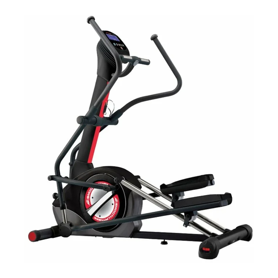
- Page 1 OWNER’S MANUAL VT-3.4 VERTICAL TRAINER Product May Vary Slightly From Picture MADE IN TAIWAN CAUTION: WEIGHT ON THIS PRODUCT SHOULD NOT EXCEED 136KG / 300LBS. VERSION: 20130108...
- Page 2 “S AFETY NSTRUCTION” WARNING: To reduce the risk of serious injury, read the following safety instructions before using the Climber. 1. Read all warnings posted on the equipment 2. Read this Owner's Manual and follow it carefully before using the equipment. Make sure that it is properly assembled and tightened before use 3.
- Page 3 “A SSEMBLY ARTS” Unpack the box in a clear area. Follow the List of Assembly Parts below to check and make sure all assembly parts are present and in good condition. Do not dispose of the packing material until the assembly process is completed. Assembly tools and hardware kit have included for you to use when assembling the product Console Upper Cover Console Bottom Cover...
- Page 4 “H ARDWARE DENTIFICATION HART” Unpack the box in a clear area. Follow the List of Hardware Kit below. This chart is provided to help identify the hardware used in the assembly process. Place the washers, the end of bolts, or screws on the circles to check for the correct diameter.
-
Page 5: Hardware Kit
“H ARDWARE DENTIFICATION HART” 109 Carriage Bolt (M8xp1.25x90mm) 2 pcs Q’TY Part No. and Description HARDWARE KIT 112 Nylon Nut (M8xp1.25) 4 pcs 131 Self-Tapping Screw, Flat Head (M4x10mm) 6 pcs Q’TY Part No. and Description HARDWARE KIT 79 Lock Washer (M8) 1 pcs 80 Washer (8x16x2.0t) 1 pcs... - Page 6 “B EFORE EGIN” Thank you for choosing the Smooth Fitness Vertical Too often, our busy lifestyles limit our time and Trainer. We take great pride in producing this quality opportunity to exercise. This equipment provides a product and hope it will provide many hours of quality convenient and simple method to begin your journey exercise so that you may reach your fitness goals.
- Page 7 “A SSEMBLY NSTRUCTIONS” – TEP 1 Front Stabilizer To allow for Assembly easier assembly do not fully a. Attach the Front Stabilizer (2) to tighten the sliding rail the Main Frame (1). assembly bolts until step3 is NOTE: Insert all the screws and completed bolts from each step before fully tightening them.
- Page 8 “A SSEMBLY NSTRUCTIONS” – TEP 4 Upright Sleeve & Upright Post Assembly a. Slide the Upright Sleeve (37) onto the Upright Post (6). NOTE: For shipping purposes the 5pcs Nylon Nuts (M8xp1.25)(112) are preinstalled in the Main Frame (1) as pictured on the right. FIG.
-
Page 9: Step 8 - Pedal Assembly
“A SSEMBLY NSTRUCTIONS” – TEP 7 Pedal Support Arm Assembly a. Refer to the inset drawing FIG .2: Cut off the tie wrap (A) on the front end of the Right Pedal Support Arm (14). NOTE: Please be sure that the Shaft Sleeve (68) inside the Pedal Support Arm (14) does FIG. -
Page 10: Handlebar Assembly
“A SSEMBLY NSTRUCTIONS” – TEP 9 Handrail Base Cover Assembly To assemble the Handrail Base Cover (128, 129), place the Left Handrail Base Cover (128) on the inner side of the Right Middle Handlebar (11). FIG.4 Place the Right Handrail Base Cover (129) at the outer side of the Right Middle Handlebar (11). -
Page 11: Step 13 - Ac Adaptor
“A SSEMBLY NSTRUCTIONS” – TEP 12 Console Cover, Handlebar Sleeve & Upper Handlebar Assembly a. Attach the Right Console Cover (35) and the Left Console Cover (34) around the Upright Post Assembly (6). Bolt the Console Covers together (34, 35) by using the 4pcs Bolts (M5xp0.8x15mm)(91). -
Page 12: How To Adjust Console Angle
Transportation and Leveling I NSTRUCTIONS” OW TO ADJUST THE LLEVELING ENDCAPS ON THE REAR STABILIZER a. After placing the equipment in its intended location of use, check the stability of the equipment b. If the equipment has a rocking motion due to an unleveled floor. You must level the equipment by turning one or both of the Leveling End Caps (27) in the clockwise or counter-clockwise direction until the equipment sits on the floor without rocking... - Page 13 “O PERATION NSTRUCTIONS” OW TO ADJUST THE STRIDE LENGTH The Vertical Trainer is equipped with four adjustable stride length options ranging from 19’’ (483mm) to 22’’ (539mm) a. To adjust the stride length, loosen and pull the Spring Knob (48). Slide the Pivoting Arm (12) up or down to the proper desired position b.
-
Page 14: Computer Operation
To set up your account, refer to the instructions in the Getting Started Guide contained in your Smooth Fitness customer care kit or visit www.my smoothtrainer.com *Not all Smooth Fitness products include the Smooth Customer Care Kit... - Page 15 COMPUTER OPERATION MySmooth Bluetooth Compatible INTRODUCING MYSMOOTH VIRTUAL TABLET-BASED FITNESS CONTROLS, ALLOWING YOU TO IMMERSE THEMSELVES IN VIRTUAL OUTDOOR WORKOUT EXPERIENCES THROUGH FULL MOTION VIDOES AND INTERACTIVE CAPABILIATES BENEFITS: • The app is FREE. The app is available through the iTunes store and the Android Market. You must purchase the optional Bluetooth module •...
-
Page 16: Program List
COMPUTER OPERATION ake a few minutes to review the console layout. Below is an overview of the console’s features and functions e recommend that you use the console to help vary your workout routine and keep you focused on your progress toward your fitness goals. - Page 17 COMPUTER OPERATION onsole uttons START/PAUSE a. Press to begin your exercise START/PAUSE b. Press again to pause all functions during your exercise program. All the data on the display will then pause. START/PAUSE c. Press again to resume the program and all the data displayed will continue until the program has finished.
-
Page 18: C Onsole B Uttons
. Then sync your MY Smooth Virtual Fitness Trainer USB device. Once complete simply plug in the MY Smooth Virtual Fitness Trainer USB device to you compatible Smooth Fitness exercise machine. Displayed on the equipment will be your name, weight height and age. - Page 19 COMPUTER OPERATION onsole unctions CALORIES: Count Up: Measuring total calories your body burned during exercise. Display range: 0 ~ 9999. SPEED: Displays the current speed KM/MILE during exercise. RPM (Revolutions Per Minute): Display range: 0 ~ 999. TIME: ...
- Page 20 COMPUTER OPERATION GENDER: Display range: Male: Female: AGE: Display range: 10 ~ 99 years old; in 1 year increments NOTE: Although the console allows an age entry beginning at 10 years old, the product is not recommended for use by children. HEIGHT: ...
- Page 21 COMPUTER OPERATION “1” Press any button on the console to turn on the computer a. Make sure that the power cord is properly plugged into the socket. b. The computer would automatically shut off after 5 minutes of inactivity. c. Press any button on the console to turn on the computer. After a few seconds, the display will then light up with a short beep sound, indicating the computer is ready for use.
- Page 22 COMPUTER OPERATION “B. SET YOUR GENDER“ MANUAL PROGRAM press ENTER to Confirm UP or Down a. After pressing the buttons to enter into , the GENDER setting will appear with /Male icon display flashing. UP or DOWN b. Use the buttons to set your gender (Male: or Female: ENTER...
-
Page 23: Changing The Resistance
COMPUTER OPERATION “F. SET THE TIME“ a. The TIME setting will appear with “TIME” flashing on the display. UP or DOWN b. Use the buttons to set the desired TIME (00:00 TO 99:00; in 1 MINUTE INCREMENTS). ENTER c. Press the button to confirm. - Page 24 COMPUTER OPERATION “C NSTRUCTIONS – ONSOLE ROGRAM (P2 ~ P10)” “A.“ENTER THE PRESET PROGRAMS” To enter one of the nine preset programs. a. Press any button on the console to turn on the computer. After a few seconds, the display will then light up with a short beep sound, indicating the computer is ready for use.
- Page 25 COMPUTER OPERATION “D. SET YOUR HEIGHT“ a. The HEIGHT setting will appear with HEIGHT flashing on the display. UP or DOWN b. Use the buttons to set your HEIGHT (3 FEET 4 INCHES ~ 7 FEET; in 1 INCH INCREMENTS/ 101 ~ 214 CM; in 1 CM INCREMENTS). ENTER c.
- Page 26 COMPUTER OPERATION “G. START TO EXERCISE” START/ PAUSE Press to begin your exercise. “H. CHANGING THE RESISTANCE SETTING” UP or DOWN You can change the resistance level (from 1 to 16 levels) at any time during workout by pressing the button...
- Page 27 COMPUTER OPERATION P1 WEIGHT LOSS P2 NOVICE INTERVAL P3 INTERMEDIATE INTERVAL P4 MOUNTAIN CLIMB P5 HILL CLIMB P6 ROLLING HILLS P7 GRADUATING INTERVAL P8 PLATEAU P9 ADVANCED INTERVAL P10 LADDER...
- Page 28 COMPUTER OPERATION “C NSTRUCTIONS – ONSOLE ROGRAM (P11 ~ 12)” P11 USER 1 P12 USER 2 “1” To enter one of the 2 USER programs. a. Press any button on the console to turn on the computer. After a few seconds, the display will then light up with a short beep sound, indicating the computer is ready for use.
- Page 29 COMPUTER OPERATION “C NSTRUCTIONS – ONSOLE ROGRAM (P11 ~ 12)” C. SET YOUR AGE“ a. The AGE setting will appear with “AGE” flashing on the display. UP or DOWN b. Use the buttons to set your AGE (10 ~ 99 YEARS OLD; in 1 YEAR INCREMENTS). ENTER c.
- Page 30 COMPUTER OPERATION “C NSTRUCTIONS – ONSOLE ROGRAM (P11 ~ 12)” F. SET THE TIME“ g. The TIME setting will appear with “TIME” flashing on the display. UP or DOWN h. Use the buttons to set the desired TIME (00:00 TO 99:00; in 1 MINUTE INCREMENTS).
- Page 31 COMPUTER OPERATION “C NSTRUCTIONS – H.R.C. P ONSOLE ROGRAM (P13)” “1” Press any button on the console to turn on the console Press any button on the console to turn on the computer. After a few seconds, the display will then light up with a short beep sound, indicating the computer is ready for use.
- Page 32 COMPUTER OPERATION “C. SET YOUR AGE“ a. The AGE setting will appear with “AGE” flashing on the display. UP or DOWN b. Use the buttons to set your AGE (10 ~ 99 YEARS OLD; in 1 YEAR INCREMENTS). ENTER c. Press the button to confirm.
- Page 33 COMPUTER OPERATION “C H.R.C. P NSTRUCTIONS – ONSOLE ROGRAM (P13)” “G. SET THE TARGET HEART RATE a. The TARGET HEART RATE will appear with the value of the TARGET HEART RATE flashing on the display. UP or DOWN b. Press the buttons to set your desired TARGET HEART RATE (50 ~ 180 BPM (BEATS PER MINUTE;...
-
Page 34: Console Instructions
COMPUTER OPERATION “C H.R.C. I NSTRUCTIONS – ONSOLE NTERVAL ROGRAM (P14)” “1” Prior information: Press any button on the console or begin pedaling to turn on the console Make sure that the power cord is properly plugged into the socket. The console would automatically shut off after 5 minutes of inactivity. - Page 35 COMPUTER OPERATION “C H.R.C. I NSTRUCTIONS – ONSOLE NTERVAL ROGRAM (P14)” ““C. SET YOUR AGE“ a. The AGE setting will appear with “AGE” flashing on the display. UP or DOWN b. Use the buttons to set your AGE (10 ~ 99 YEARS OLD; in 1 YEAR INCREMENTS).
- Page 36 COMPUTER OPERATION “C H.R.C. I NSTRUCTIONS – ONSOLE NTERVAL ROGRAM (P14)” “G. SET THE HIGH TARGET HEART RATE“ Average Max./High Heart Rate 75% a. The HIGH TARGET HEART RATE setting will 150 beats per minute appear with the value of HIGH TARGET HEART 146 beats per minute RATE flashing on the display.
-
Page 37: Heart Rate
COMPUTER OPERATION H.R.C. I NSTRUCTIONS – ONSOLE NTERVAL ROGRAM (P14)” J. MUST-KNOWN HEART RATE PROGRAM INFO.” The CONSOLE MONITOR will help you reach your ideal LOW & HIGH TARGET HEART RATE a. 3 minute WARM UP time: After entering the H.R.C. Interval program, the program will begin with a 3 minute WARM UP period, during the WARM UP period, the console will detect the user’s heart rate through the hand pulse sensors or wireless chest belt. -
Page 38: Muscle Chart
MUSCLE CHART Targeted muscle groups: The exercise routine that is performed on this product will develop primarily lower body muscle groups. These muscle groups are shown in gray color on the chart below. MUSCLE GROUPS Shoulder muscles Calf muscles Pectoral muscles Trapezius muscles Bicep muscle Tricep muscles... -
Page 39: Stretching Routine
STRETCHING ROUTINE Warm up and cool down: A successful exercise program consists of a warm-up, aerobic exercise, and a cool-down. Do the entire program at least two and preferably three times a week, resting for a day between workouts. After several months, you can increase your workouts to four or five times per week. -
Page 40: Parts Drawing
“P RODUCT ARTS RAWING (A)”... - Page 41 “P RODUCT ARTS RAWING (B)”...
- Page 42 “P IST” NO. Part Name Q'ty NO. Part Name Q'ty Main Frame 36 Rotator Cuff Front Stabilizer 37 Upright Sleeve Rear Stabilizer 38 Hand Pulse Upper Cover Left Sliding Rail 39 Hand Pulse Bottom Cover Right Sliding Rail 40 Handlebar Decoration Cover Upright Post 41 Round Plug Fixed Handlebar...
- Page 43 “P IST” NO. Part Name Q'ty NO. Part Name Q'ty 72 Bearing (6300) 103 Bolt (M8×p1.25×20mm) 73 Spacer (10×14×2mm) 104 Bolt (M8×p1.25×50mm) 74 C-Ring 105 Bolt (M8×p1.25×65mm) 75 E-Ring 106 Bolt (M8×p1.25×90mm) 76 Eye Bolt 107 Bolt (M10×p1.5×85mm) 77 Tension Bracket 108 Bolt (M8×p1.25×16mm) Carriage Bolt 78 Wave Washer...
-
Page 44: Warranty
Hire and reimburse an independent service technician who will come into the home for the repair, In the event that there is not an available certified Smooth Fitness service technician, Smooth will send the part directly to the consumer and will pay $75 US per occurrence for the labor costs of such repair.