
Related Manuals for Smooth Fitness V2300


Summary of Contents for Smooth Fitness V2300
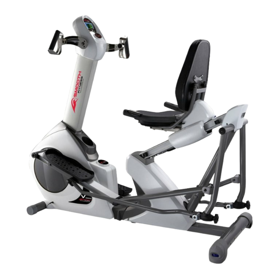
- Page 1 OWNER’S MANUAL www.smoothfitness.com 2300 RECUMBENT ELLIPTICAL / BIKE MAXIMUM USER WEIGHT LIMIT 300LBS. MADE IN TAIWAN V. II...
- Page 2 “S AFETY NSTRUCTION” WARNING: To reduce the risk of serious injury, read the following safety instructions before using the 2 in 1 Recumbent Elliptical / Bike 1. Read all warnings posted on the equipment 2. Read this Owner's Manual and follow it carefully before using the equipment. Make sure that it is properly assembled and tightened before use 3.
- Page 3 “A SSEMBLY ARTS” Unpack the box in a clear area. Follow the List of Assembly Parts below to check and make sure all assembly parts are present and in good condition. Do not dispose of the packing material. Assembly tools and hardware kit are included for assembling the product Handlebar Assembly Connection Cover...
- Page 4 “H ARDWARE DENTIFICATION HART” Unpack the box in a clear area. Follow the List of Hardware Kit below. This chart is provided to help identify the hardware used in the assembly process. Place the washers, the end of bolts, or screws on the circles to check for the correct diameter.
- Page 5 Part No. and Description Q’TY HARDWARE KIT 58 Screw Cap 2 pcs 121 Lock Washer (M8) 14 pcs 123 Washer (8x16x2.0t) 14 pcs 131 Self-Tapping Screw, Truss Head (M4x20mm) 1 pcs 138 Screw, Round Head (M5xp0.8x15mm) 2 pcs 153 Bolt, Button Head (M8xp1.25x20mm) 4 pcs 155 Bolt, Button Head (M8xp1.25x40mm) 2 pcs...
- Page 6 “B EFORE EGIN” 2 in 1 Recumbent Too often, our busy lifestyles limit our time and Thank you for choosing the Elliptical / Bike opportunity to exercise. This equipment will provide a . We take great pride in producing this convenient and simple way to begin your journey of quality product and hope it will provide you many hours of quality exercise to making you look and feel...
-
Page 7: Step 2 - Handlebar Assembly
“A SSEMBLY NSTRUCTIONS” USE HARDWARE KIT – TEP 1 Front Stabilizer Assembly a. Identify the correct direction of the Front Stabilizer (7), there is an “R” decal on the right side of the Front Stabilizer (7)(NOTE: Right and left orientation is from the seated position). b. -
Page 8: Step 4 - Leveler Assembly
“A SSEMBLY NSTRUCTIONS” USE HARDWARE KIT – TEP 3 Rear Stabilizer Assembly a. Attach the Rear Stabilizer (8) to the Rear Support Frame Assembly (2). “Helpful Hint: Only hand tighten the bolts and fasteners in each step. Wait until the step is completed before fully tightening the bolts and fasteners”... - Page 9 “A SSEMBLY NSTRUCTIONS” USE HARDWARE KIT – TEP 6 Seat Support Slider Assembly Slide the Seat Support Slider Assembly (5) into the Outer Seat Support Slider (4) and secure with four Washers (8x16x2.0t)(123), four Lock Washers (M8)(121), four Bolts, Button Head (M8xp1.25x20mm)(153) NOTE: Do not fully tighten the above washers, lock washers and bolts until Step.
- Page 10 “A SSEMBLY NSTRUCTIONS” USE HARDWARE KIT – TEP 8 Short Extension Pulse Wire & Rail Decoration Assembly a. Follow FIG.1 to plug the Short Extension Pulse Wire (183) into the connector located on the front bottom side of the Seat Rail (91). b.
- Page 11 “A SSEMBLY NSTRUCTIONS” USE HARDWARE KIT – TEP 10 Seat and Seat Handlebar Assembly a. Locate and secure the Seat Handlebar (11) on the Seat Frame (10) with two Carriage Bolts (M8xp1.25x50mm)(163) and two Nylock Nuts (M8x1.25)(171). NOTE: Be careful not to pinch the Pulse Sensor Wire 4 (184). b.
- Page 12 “A SSEMBLY NSTRUCTIONS” USE HARDWARE KIT Please be sure that Bolt (157) would screw through the Shaft Sleeve (106) inside the rear end of the Right Pedal Support Arm Assembly (14) during assembly – TEP 11 Pedal Support Arm Assembly NOTE: Two Washers (6x19x2.0t)(122) and two Bolts, Hex Head (M8xp1.25x16mm)(146) are pre-attached on the Rotation Stand (17) as the figure shows on the right.
-
Page 13: Step 13 - Ac Adaptor
“A SSEMBLY NSTRUCTIONS” After fully securing Bolt, USE HARDWARE KIT Button Head (155) and Nylock Nut (M8)(171), slightly loosen the Bolt (155) with ¼ turn in the counter-clockwise direction to release excess pressure from Pedal Linkage – TEP 12 Pedal Linkage and Pedal Assembly a. -
Page 14: How To Move The Item Safely
“O PERATION NSTRUCTIONS” OW TO ADJUST THE ADJUSTING ENDCAPS OF THE REAR STABILIZER a. After placing the equipment in the intended location for use, check the stability of the equipment. b. To level the equipment, turn one or both of the Adjusting Rear Stabilizer EndCaps (37) in clockwise or counter-clockwise direction until the equipment sets on the floor without rocking. -
Page 15: How To Adjust The Seat
“O PERATION NSTRUCTIONS” HOW TO ADJUST THE SEAT a. To adjust the seat distance from the pedals, it’s suggested to place your feet on each pedal. b. Use your right hand to lift up the Adjusting Handle (A) while using your feet to slide the seat distance forward or backward until the seat reaches to the proper position. -
Page 16: Step Mode
“O PERATION NSTRUCTIONS” HOW TO CHANGE THE WLLIPTICAL BIKE MOTION STEP MODE: The item can be used in the ELLIPTICAL mode or the STEP mode. Refer to the following process to set up the ELLIPTICAL mode or the STEP mode. a. - Page 17 ※ To change to ELLIPTICAL mode, make sure the Pedal Linkage (19) is attached to the Pivoting Arm (13)
-
Page 18: Console Buttons
“C ONSOLE NSTRUCTIONS” ower a. Make sure the item’s adaptor is correctly plugged into the socket b. Pedaling or pressing any keys to active the console. The console display will then light up with a short beep sound, indicating the console will be ready for use ower... -
Page 19: Program Descriptions
“C ONSOLE NSTRUCTIONS” CONSOLE FUNCTIONS Automatically scans TIME, SPEED, CALORIE, PULSE, and DISTANCE in sequence with a SCAN change every five seconds. Press and release the MODE button until the arrow points to "SCAN” TIME TIME: Count Up: If a target time was not selected, TIME will count up from 0:00 to maximum 99:59 minutes ... - Page 20 “C “ ONSOLE ROUBLE HOOTING UIDE PROBLEM POSSIBLE CAUSE SOLUTION 1. Motor Malfunction Replace Motor 2. Magnetic System Replace Magnetic System/Flywheel Malfunction or got stuck No Motor signal 3. Connection Wires are not Check whether the wires are well-connected or replace the well-connected or broken broke wires with the new wires 4.
-
Page 21: Troubleshooting Guide
“C “ ONSOLE ROUBLE HOOTING UIDE PROBLEM POSSIBLE CAUSE SOLUTION The connection between the Circuit Board and the LCD Membrane is loose. Verify that the Circuit Board is securely fastened to the Computer Case. Retighten the Gently press Screws. Take care NOT to over tighten the Screws as this may destroy the Circuit down on the LCD Board. - Page 22 “C ONDITIONING UIDELINES” How you begin your exercise program depends on your physical condition. If you have been inactive for several years, or are severely overweight, you must slowly and increase your time on the 2 in 1 Elliptical / Bike gradually: a few minutes per workout.
- Page 23 “W ARM- P AND OOL- OWN” Warm-up The purpose of warming up is to prepare your body for exercise and to minimize injuries. Warm up for two to five minutes before strength-training or aerobic exercising. Perform activities that raise your heart rate and warm the working muscles.
-
Page 24: Parts Drawing
“P RODUCT ARTS RAWING (A)”... - Page 25 “P RODUCT ARTS RAWING (B)”...
- Page 26 “P IST” Item Name Q'TY Item Name Q'TY Main Frame 34 Bearing Housing Rear Support Frame 35 Transportation Wheel (L&R) Rail Pivot 36 Round EndCap Outer Seat Support Slider 37 Adjusting Rear Stabilizer EndCap Inner Seat Support Slider 38 leveler Handlebar (L&R) 39 Bushing (60x10mm) Front Stabilizer...
- Page 27 IST” Item Name Q'TY Item Name Q'TY 67 Pivoting Arm Connector (L&R) 100 Spring for Fixing Pin 68 Locking Knob (L&R) 101 Spring for Adjusting Handle Stand 69 Bushing (25.4x12mm) 102 Bushing for Seat Wheel 70 Bushing (25.4x16.5mm) 103 Spacer (8×12×6.5mm) 71 Bushing (38.5x12mm) 104 Spacer (8×12×7.5mm) 72 Left Rail Connection Cap...
- Page 28 IST” Item Name Q'TY Item Name Q'TY Self-Tapping Screw, Truss Head 164 Carriage Bolt (M8×p1.25×90mm) (M5×18mm) Self-Tapping Screw, Truss Head 165 Bolt, Button Head (M6×p1.0×40mm) (M5×25mm) 166 Grub Screw Self-Tapping Screw, Button Head (M4×15mm) 167 Nut (M6×p1.0) 136 Screw, Pan Head (M5x12mm) 168 Nut (M8×p1.25) 138 Screw, Round Head (M5×p0.8×15mm) 169 Nylock Nut (M5×p0.8)
- Page 29 Hire and reimburse an independent service technician, who will come into the home for the repair, In the event that there is not an available certified Smooth Fitness service technician, Smooth will send the part directly to the consumer and will pay $75 US per occurrence for the labor costs of such repair.