Table of Contents
Advertisement
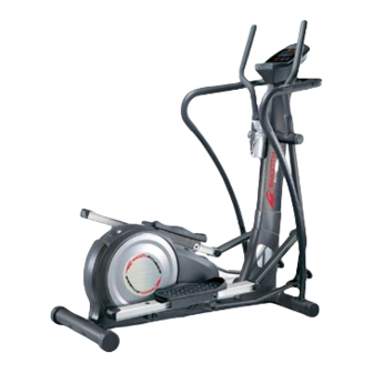
CE-3.0DS
Owners' Manual
WARNING
Exercise can present a health risk. Consult a
physician before beginning any exercise
program with this equipment.
If you feel faint or dizzy, immediately
discontinue use of this equipment. Serious
bodily injury can occur if this equipment is not
assembled and used correctly. Serious bodily
injury can also occur if all instructions are not
followed.
Keep children and pets away from
equipment. Always make sure all bolts and
nuts are tightened prior to each use. Follow
all safety instructions in this manual.
CAUTION: WEIGHT ON THIS PRODUCT
SHOULD NOT EXCEED 136KG / 300LBS.
Product May Vary Slightly From Pictures
Advertisement
Table of Contents

Related Manuals for Smooth Fitness CE-3.0DS


Summary of Contents for Smooth Fitness CE-3.0DS
- Page 1 CE-3.0DS Owners’ Manual WARNING Exercise can present a health risk. Consult a physician before beginning any exercise program with this equipment. If you feel faint or dizzy, immediately discontinue use of this equipment. Serious bodily injury can occur if this equipment is not assembled and used correctly.
- Page 2 SAFETY INSTRUCTIONS WARNING: To reduce the risk of serious injury, read the following Safety Instructions before using CE-3.0DS. 1. Read all warnings posted on the equipment 2. Read this Owner's Manual and follow it carefully before using the equipment. Make sure that it is properly assembled and tightened before use 3.
- Page 3 “B EFORE EGIN” Thank you for choosing the CE-3.0DS. We take Too often, our busy lifestyles limit our time and great pride in producing this quality product and hope opportunity to exercise. The equipment provides a it will provide many hours of quality exercise to make convenient and simple method to begin your journey you feel better, look better and enjoy life to its fullest.
- Page 4 “H ARDWARE DENTIFICATION HART” Unpack the box in a clear area. Use the List of Hardware below to check the contents of the hardware kit. This chart is provided to help identify the hardware used in the assembly process. Place the washers, the end of bolts, or screws on the circles to check for the correct diameter.
- Page 5 “A SSEMBLY NSTRUCTIONS” – TEP 1 Stabilizer Assembly a. Attach the REAR STABILIZER(2), the one with LEVELING CAP 76mm(76), onto the MAIN FRAME(1) with 2 x CARRIAGE BOLTS(M8x85mm)(104) and Nylon lock Nut (M8)(105). b. Attach the FRONT STABILIZER(3) onto the MAIN FRAME(1) with SOCKET HEAD BOLTS (M8x90mm)(94) and LOCK WASHERS(M8)(108).
- Page 6 “A SSEMBLY NSTRUCTIONS” Prior to assembling check that Bolt (100) properly fits through Shaft Sleeve (54) located on the Right and Left Pedal Arm Assembly (14). NOTE: Part (15) must have the rectangular portion facing the rear of the machine when installing pedal arm –...
- Page 7 “A SSEMBLY NSTRUCTIONS” – TEP 5 Wire & Stationary Handlebar Assembly a. Connect the MIDDLE PULSE SENSOR WIRE(41A) and the LOWER PULSE SENSOR WIRE (42A). b. Connect the MIDDLE PULSE SENSOR WIRE(41B) and the LOWER PULSE SENSOR WIRE (42B). NOTE: Be careful not to pinch the wires c.
- Page 8 “A SSEMBLY NSTRUCTIONS” – TEP 7 Handlebar Assembly a. There is an “R” decal on the RIGHT HANDLEBAR(10) and an “L” decal on the LEFT HANDLEBAR(9). Slide the HANDLEBAR SLEEVE(48) onto the RIGHT HANDLEBAR(10). b. Attach the RIGHT HANDLEBAR(10) into the RIGHT PIVOTING ARM(12) with 2 x SOCKET HEAD BOLTS(M6x35mm)(90) and 2 x NYLON LOCK NUTS(M6)(102).NOTE: Assemble the SOCKET HEAD BOLTS(M6x35mm)(90) by following the direction as shown by the drawing c.
- Page 9 “S P & PERATIONAL NSTRUCTIONS” LEVELING: Adjust the LEVELING CAPS(76) on the REAR STABILIZER(2) so that the item sets on the floor without rocking. Reposition the LEVELING CAPS(76) on the REAR STABILIZER(2) in order to level the item. MOVING: a. Before moving the CE-3.0DS, Make sure the unit is in Elliptical Mode Pictured below. b.
- Page 10 “C ONSOLE NSTRUCTIONS” ake a few minutes to review the console layout. Below is an overview of the console’s features and functions e recommend that you use the console to help vary your workout routine and keep you focused on your progress toward your fitness goals.
- Page 11 “C NSTRUCTIONS – ” ONSOLE ONSOLE UTTONS onsole uttons START/PAUSE a. Press to begin your exercise START/PAUSE b. Press again to stop and pause all functions during your exercise program. All the data on the display will then freeze. START/PAUSE c.
- Page 12 “C NSTRUCTIONS – ” ONSOLE ONSOLE UTTONS START/PAUSE During workout (after pressing ), pressing the mode button will scroll between Speed/Distance/Calories or RPM/ODO/Watts RPM, ODO, WATT will be displayed simultaneously SPEED, DISTANCE, CAL will be displayed simultaneously DISTANCE and ODO (ODOMETER) information: ...
- Page 13 “C ONSOLE NSTRUCTIONS”– ONSOLE UNCTIONS” onsole unctions PROGRAM: The console comes with 16 preset programs Displays programs from P1 ~ P16 during set up Displays the selected program during exercise LEVEL: Displays resistance level of the current program, from 1 to 16 resistance levels in 1 level increments TIME: ...
- Page 14 “C ONSOLE NSTRUCTIONS”– ONSOLE UNCTIONS” CALORIES: Count Up: If target calories were not selected, this measures total calories your body burned during exercise Count Down: If you have set the preference value of calories, the console will count down from that selected target calories down to 0 BMR: (calculations are estimated) ...
- Page 15 “C NSTRUCTIONS – ONSOLE ANUAL ROGRAM (P1)” “1” Press any button on the console or begin pedaling to turn on the console a. Make sure that the power cord is properly plugged into the socket. b. The console would automatically shut off after 4 minutes of inactivity c.
- Page 16 “C NSTRUCTIONS – ONSOLE ANUAL ROGRAM (P1)” “B. SET TIME or DISTANCE To avoid confusion the user can only set time or distance in any one program. TO ENTER TIME: TO ENTER DISTANCE: UP or DOWN ENTER UP or DOWN button: button and then button:...
- Page 17 “C NSTRUCTIONS – ONSOLE ANUAL ROGRAM (P1)” 2. Age Selection ENTER a. Press button to confirm the CALORIES value and enter the mode to set the AGE UP or DOWN b. Use buttons to set your AGE. Press ENTER to confirm (10 TO 99 YEARS OLD;...
- Page 18 “C NSTRUCTIONS – ONSOLE ANUAL ROGRAM (P1)” G. TARGET HEART RATE” The target heart rate is based on the Age that is set into the computer during setup. The TARGET HEART RATE calculation is based on 85% of the maximum heart rate. For example: For a 30-year-old user, the max.
- Page 19 “C NSTRUCTIONS – ONSOLE ROGRAM (P2 ~ P7)” “1” Press any button on the console or begin pedaling to turn on the console d. Make sure that the power cord is properly plugged into the socket. e. The console would automatically shut off after 4 minutes of inactivity Press any button on the console or begin pedaling to turn on the console.
- Page 20 “C NSTRUCTIONS – ONSOLE ROGRAM (P2 ~ P7)” “B. SET TIME or DISTANCE To avoid confusion the user can only set time or distance in any one program. TO ENTER TIME: TO ENTER DISTANCE: UP or DOWN ENTER UP or DOWN button: button and then button:...
- Page 21 “C NSTRUCTIONS – ONSOLE ROGRAM (P2 ~ P7)” “C. SET CALORIES and AGE” 1. Calories a. After confirming the TIME or DISTANCE UP or DOWN b. Use buttons to set the desired CALORIES press enter to confirm (10 TO 9990KCAL; 10 KCAL INCREMENT) NOTE for CALORIES: ...
- Page 22 “C NSTRUCTIONS – ONSOLE ROGRAM (P2 ~ P7)” “F. CHANGING THE RESISTANCE LEVEL” UP or DOWN he resistance Press the button to change t level (from 1 to 16 levels) at any time during the workout. G. TARGET HEART RATE” ...
- Page 23 “C NSTRUCTIONS – ONSOLE ROGRAM (P8)” “A.“ENTER BODY FAT PROGRAM (P8)” START/PAUSE button: BODY FAT PROGRAM (P8) UP or DOWN b. Press button to select BODY FAT PROGRAM (P8) ENTER c. Press button to enter the “B. SET THE PERSONAL INFORMATION ( GENDER, HEIGHT and AGE )”...
- Page 24 “C NSTRUCTIONS – ONSOLE ROGRAM (P8)” “C. START TESTING YOUR BODY FAT” START/ PAUSE Press to start the test. The testing time takes about 10 seconds, please review the information below that corresponds to the test results. “D. THE BODY FAT RESULT INFORMATION”...
- Page 25 “C NSTRUCTIONS – ONSOLE ROGRAM (P8)” “D. THE BODY FAT RESULT INFORMATION” 4. BODY TYPE: Refer to the following list to determine what your body type is: Type 1 5% ~ 9% Underweight Type 2 10% ~ 14% Slim Class (fat %) (fat %) Type 3...
- Page 26 “C NSTRUCTIONS – ONSOLE ROGRAM (P9 ~ P12)” T.H.R. 60% H.R.C. 75% H.R.C. 85% H.R.C. “3” H.R.C. PROGRAM (P9~P12) “A.“ENTER H.R.C. PROGRAM (P9~P12)” START/PAUSE a. Press button to activate the computer. H.R.C. PROGRAM (P9 ~ P12) UP or DOWN b. Press button to select H.R.C.
- Page 27 “C NSTRUCTIONS – ONSOLE ROGRAM (P9 ~ P12)” “ E. MUST-KNOWN HEART RATE PROGRAM INFO.” a. FORMULA OVERVIEW: BEGINNER: 60% of maximum heart rate; 60% of (220 – your age) TRAINER: 75% of maximum heart rate; 75% of (220 – your age) ACTIVE TRAINER: 85% of maximum heart rate;...
- Page 28 “C NSTRUCTIONS – ONSOLE ROGRAM (P9 ~ P12)” If you do not place your hands correctly, and a few seconds pass without a pulse input, the console will turn off the pulse circuit. The console will then display an error message “P”. Remove your hands from the sensor then replace your hands back on the Pulse Sensors correctly, the pulse readout will appear again “H.CHANGING THE RESISTANCE”...
- Page 29 “C NSTRUCTIONS – ONSOLE ETTING ROGRAM (P13 ~ P16)” “A.“ENTER USER MODE PROGRAM (P13~P16)” START/PAUSE a. Press button to activate the computer USER MODE PROGRAM (P13 ~ P16) UP or DOWN b. Press button to select USER MODE PROGRAM (P13 ~ P16) ENTER c.
- Page 30 “C NSTRUCTIONS – ONSOLE ETTING ROGRAM (P13 ~ P16)” TO ENTER TIME: TO ENTER DISTANCE: UP or DOWN ENTER UP or DOWN button: button and then button: User Program User Program e. After entering the the TIME function After entering the the TIME function mode will appear with the display flashing “0:00”.
- Page 31 “C NSTRUCTIONS – ONSOLE ETTING ROGRAM (P13 ~ P16)” “E. SET THE RESISTANCE LEVEL” The USER SETTING PROGRAM allows the user to manually set the resistance level, the console will divide the time into 10 intervals. a. Enter the program to set the EACH TIME INTERVAL RESISTANCE LEVEL (1 TO 16 RESISTANCE LEVELS), then press ENTER button to confirm and move to the next interval b.
- Page 32 “C NSTRUCTIONS – ONSOLE ETTING ROGRAM (P13 ~ P16)” “H.CHANGING THE RESISTANCE” UP or DOWN he resistance Press the button to change t level (from 1 to 16 levels) at any time during the workout. I. TARGET HEART RATE” The target heart rate is based on the Age that is set into the computer during setup. The TARGET HEART RATE calculation is based on 85% of the maximum heart rate.
-
Page 33: Troubleshooting
“C “ ONSOLE ROUBLE HOOTING UIDE PROBLEM POSSIBLE CAUSE SOLUTION 1. Motor Malfunction Replace Motor 2. Magnetic System Replace Magnetic System/Flywheel Malfunction or got stuck No Motor signal 3. Connection Wires are not Check whether the wires are well-connected or replace the well-connected or broken broke wires with the new wires 4. - Page 34 “C “ ONSOLE ROUBLE HOOTING UIDE PROBLEM POSSIBLE CAUSE SOLUTION Verify the gap between Speed Sensor and the Magnet is 5mm or less The Computer isn’t receiving a Verify that all the Wire Plugs are connected FIRMLY, correctly and are not signal from the Speed damaged The Speed...
- Page 35 “C ONDITIONING UIDELINES” How you begin your exercise program depends on your physical condition. If you have been inactive for several years, or are severely overweight, you must slowly and increase your time on the item gradually: a few minutes per workout. Initially, you may be able to exercise only for a few minutes in your target zone, however, your aerobic fitness will improve over the next six to eight weeks.
- Page 36 “W ARM- P AND OOL- OWN” Warm-up The purpose of warming up is to prepare your body for exercise and to minimize injuries. Warm up for two to five minutes before strength-training or aerobic exercising. Perform activities that raise your heart rate and warm the working muscles.
- Page 37 “P RODUCT ARTS RAWING”...
- Page 38 PARTS LIST PART NAME PART NAME CE-3.0-1 Main Frame CE-3.0-42 Lower Pulse Sensor Wire CE-3.0-2 Rear Stabilizer CE-3.0-43 Linkage Connector CE-3.0-3 Front Stabilizer CE-3.0-44 Locking Knob CE-3.0-4 Upright Post CE-3.0-45 Connector CE-3.0-5 Left AL Upright CE-3.0-46 Console CE-3.0-6 Right AL Upright CE-3.0-47 Foam Grip CE-3.0-7 Left Stationary Handlebar CE-3.0-48 Handlebar Sleeve...
- Page 39 PARTS LIST PART NAME CE-3.0-84 Screw, M4x16mm CE-3.0-85 Screw, M4x20mm CE-3.0-86 Bolt, Round Head M5x12mm CE-3.0-87 Screw, M5x10mm CE-3.0-88 Screw, M5x20mm CE-3.0-89 Screw, M6x10mm CE-3.0-90 Bolt, Socket Head, M6x35mm CE-3.0-91 Screw, M8x16mm CE-3.0-92 Bolt, Socket Head M8x25mm CE-3.0-94 Bolt, Socket Head M8x90mm CE-3.0-95 Bolt, M8x16mm CE-3.0-96 Bolt, M8x25mm CE-3.0-97 Bolt, Round Head M8x16mm...
- Page 40 Procedure for Obtaining Your Remedy Under This Warranty: To obtain service on a Smooth Fitness product, call Smooth Fitness. In the instance that service is not available in an area, Smooth Fitness, at its discretion, can either 1) find a service technician in your area to perform warranty service, 2) have a local dealer perform warranty service, or 3) send the warranty parts to you and reimburse as described above.