Nordyne JS5BD SERIES User's Manual & Installation Instructions
13 seer split system air conditioner, r-22
Hide thumbs
Also See for JS5BD SERIES:
Table of Contents
Advertisement
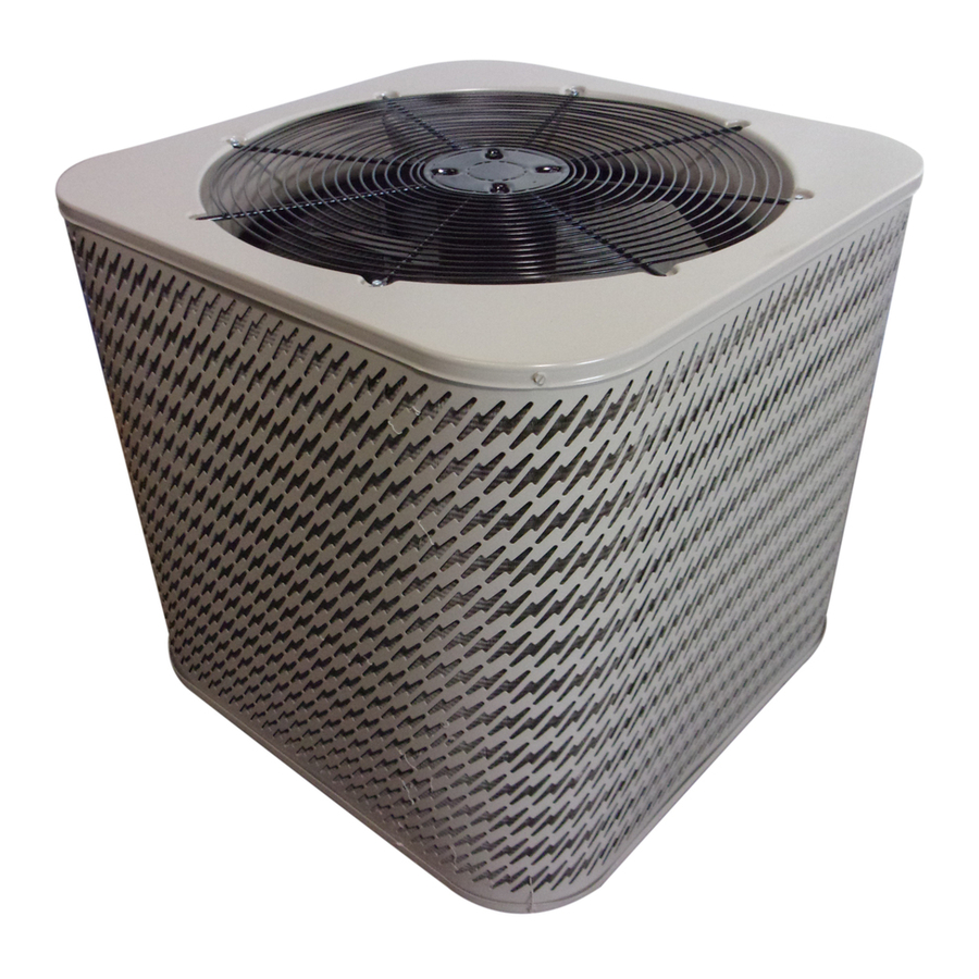
JS5BD SERIES
USER'S MANUAL / INSTALLATION INSTRUCTIONS
SPLIT SYSTEM AIR CONDITIONER - R-22
Please read this information thoroughly and become familiar with the capabilities and
use of your appliance before attempting to operate or maintain this unit. Keep this
literature where you have easy access to it in the future. If a problem occurs, check the
instructions and follow recommendations given. If these suggestions don't eliminate
the problem, call your servicing contractor.
The Installation Instructions are primarily intended to assist qualifi ed individuals
experienced in the proper installation of this appliance. Some local codes require licensed
installation/service personnel for this type of equipment. Please read all instructions
carefully before starting the installation.
IMPORTANT
DO NOT DESTROY. PLEASE READ CAREFULLY AND
KEEP IN A SAFE PLACE FOR FUTURE REFERENCE.
13 SEER
Advertisement
Table of Contents

Related Manuals for Nordyne JS5BD SERIES


Summary of Contents for Nordyne JS5BD SERIES
- Page 1 JS5BD SERIES 13 SEER USER’S MANUAL / INSTALLATION INSTRUCTIONS SPLIT SYSTEM AIR CONDITIONER - R-22 IMPORTANT Please read this information thoroughly and become familiar with the capabilities and use of your appliance before attempting to operate or maintain this unit. Keep this literature where you have easy access to it in the future.
-
Page 2: Table Of Contents
USER INFORMATION WARRANTY INFORMATION Important Safety Information ........3 A warranty certifi cate with full details is included with the Operating Instructions ..........3 air conditioner. Carefully review these responsibilities with Cooling Operation .............3 your dealer or service company. The manufacturer will not Heating Operation .............3 be responsible for any costs found necessary to correct Operating the Air Conditioner for Automatic... -
Page 3: Important Safety Information
USER INFORMATION IMPORTANT SAFETY INFORMATION The continuous indoor blower operation can be obtained with the thermostat system mode set in any position, Safety markings are used frequently throughout this including OFF. manual to designate a degree or level of seriousness and should not be ignored. -
Page 4: Important Safety Information
INSTALLER INFORMATION IMPORTANT SAFETY INFORMATION CAUTION: INSTALLER: Please read all instructions before servicing this equipment. Pay attention to all safety warnings and This unit uses refrigerant R-22. DO NOT use any other special notes highlighted in the manual. Safety any other refrigerant in this unit. Use of another markings are used frequently throughout this manual to refrigerant will damage the unit. -
Page 5: Air Conditioner Installation
• Survey the job site to determine the best location for General Information mounting the outdoor unit. See Figure 5 (page 12) for The JS5BD series air conditioner is designed only for unit dimensions. outdoor rooftop or ground level installations. This unit has •... -
Page 6: Connecting Refrigerant Tubing Between The Indoor & Outdoor Unit
Connecting Refrigerant Tubing Between the Indoor • Installing a fi lter dryer is optional. However it is good & Outdoor Unit practice to install a fi lter dryer when replacing the evaporator and/or condensor of a system. The fi lter CAUTION: dryer must be installed in strict accordance with the manufacturer’s installation instructions. -
Page 7: Grounding
• The outdoor unit requires both power and control circuit • The thermostat should be mounted about 5 feet electrical connections. Refer to the wiring diagram / above the fl oor on an inside wall. DO NOT install the schematic for identifi cation and location of outdoor thermostat on an outside wall or any other location unit fi... -
Page 8: Startup & Adjustments
• Refrigerant charging charts are applicable only to 2. Verify blower wheel is spinning in direction indicated matched assemblies of NORDYNE equipment and by arrow. Feel the air being circulated by the indoor listed airfl ows for the indoor coil. Refer to Figures 5 -... -
Page 9: Charging R-22 Units In Ac Mode With Outdoor Temperatures Above 55° F
(in psig) at the outdoor REPLACEMENT PARTS unit service valve. Replacement parts are available through all Nordyne distributors. Please have the complete model and serial number of the unit 2. Measure the liquid refrigerant temperature (in when ordering replacement parts. -
Page 10: Figures & Tables
FIGURES & TABLES REFRIGERANT CHARGING TABLES Shaded boxes indicate fl ooded conditions. Rated design values. The suction pressure will vary from design value if indoor air fl ow, entering dry bulb, or entering wet bulb temperatures are lower than design. 1. - Page 11 REFRIGERANT CHARGING TABLES Shaded boxes indicate fl ooded conditions. Rated design values. The suction pressure will vary from design value if indoor air fl ow, entering dry bulb, or entering wet bulb temperatures are lower than design. 1. All pressures are listed in psig and all temperatures in ° F 2.
- Page 12 REFRIGERANT CHARGING TABLES Shaded boxes indicate fl ooded conditions. Rated design values. The suction pressure will vary from design value if indoor air fl ow, entering dry bulb, or entering wet bulb temperatures are lower than design. 1. All pressures are listed in psig and all temperatures in ° F 2.
-
Page 13: Refrigerant Charging Charts
OUTDOOR TEMPERATURE (° F) Suct. Press. Liq. Dis. Liq. Dis. Liq. Dis. Liq. Dis. Liq. Dis. Liq. Dis. Liq. Dis. Liq. Dis. Press. Temp. Press. Temp. Press. Temp. Press. Temp. Press. Temp. Press. Temp. Press. Temp. Press. Temp. Table 11. Charging Table for JS5BD-060 Series (5 Ton Units) TXV COOLING CHARGING CHARTS JS5BD-018 SERIES CHARGING CHART Remove refrigerant when above curve... - Page 14 JS5BD-024KB SERIES CHARGING CHART Remove refrigerant when above curve Add refrigerant when below curve Liquid Temperature (F) Figure 6. Charging Chart for 2 Ton Units (with Microchannel Coil) JS5BD-030KB SERIES CHARGING CHART Remove refrigerant when above curve Add refrigerant when below curve Liquid Temperature (F) Figure 7.
- Page 15 JS5BD-036KB SERIES CHARGING CHART Remove refrigerant when above curve Add refrigerant when below curve Liquid Temperature (F) Figure 8. Charging Chart for 3 Ton Units (with Microchannel Coil) JS5BD-042 SERIES CHARGING CHART Remove refrigerant when above curve Add refrigerant when below curve Liquid Temperature (F) Figure 9.
- Page 16 JS5BD-048 SERIES CHARGING CHART Remove refrigerant when above curve Add refrigerant when below curve Liquid Temperature (F) Figure 10. Charging Chart for 4 Ton Units JS5BD-060 SERIES CHARGING CHART Remove refrigerant when above curve Add refrigerant when below curve Liquid Temperature (F) Figure 11.
-
Page 17: Figure 12. Js5Bd Wiring Diagram
WIRING DIAGRAM Split System Air Conditioner (Outdoor Section) Single Phase NOTES: Optional Hard Start Kit 1. Couper le courant avant de faire letretien. 1. Disconnect all power before servicing. 2. Employez uniquement des conducteurs 2. For supply connections use copper conductors only. to “H”... - Page 20 ¢709234&¤ Specifi cations & illustrations subject to change without notice or incurring obligations. O’ Fallon, MO | Printed in U.S.A. (08/10) 7092340 (Replaces 7088500)