Table of Contents
Advertisement
Quick Links
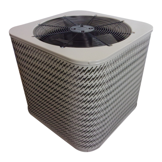
Outdoor Air Conditioner
User's Information and Installation Instructions
13+ SEER Extra High Efficiency Split System
These units have been designed and tested for
capacity and efficiency in accordance with A.R.I.
Standards. Split System Air Conditioning units
are designed for use with a wide variety of fossil
fuel furnaces, electric furnaces, air handlers, and
evaporator coil combinations.
These instructions are primarily intended to
assist qualified individuals experienced in the
proper installation of heating and/or air condi-
tioning appliances. Some local codes require
licensed installation/service personnel for this
type of equipment. Read all instructions carefully
before starting the installation.
USER'S INFORMATION
IMPORTANT
Read this owner information to become familiar
with the capabilities and use of your appliance.
Keep this with literature on other appliances
where you have easy access to it in the future.
FAN SWITCH
TEMPERATURE SCALES
If a problem occurs, check the instructions
and follow recommendations given. If these
suggestions don't eliminate your problem, call
your servicing contractor.
OPERATING INSTRUCTIONS
To Operate Your Air Conditioner for
Cooling —
1. Set the thermostat system switch to COOL
2. Set the thermostat temperature to the
SYSTEM SWITCH
Figure 1. Typical Thermostat
or AUTO and the thermostat fan switch to
AUTO. (See Figure 1)
desired temperature level using the
temperature selector. Please refer to the
separate thermostat user's manual for
complete instructions regarding ther-
mostat programming. The outdoor unit
and indoor blower will both cycle on and
off to maintain the indoor temperature at
the desired cooling level.
TEMPERATURE
SELECTOR
Advertisement
Table of Contents

Related Manuals for Nordyne DS5BD


Summary of Contents for Nordyne DS5BD
- Page 1 Outdoor Air Conditioner User’s Information and Installation Instructions 13+ SEER Extra High Efficiency Split System These units have been designed and tested for If a problem occurs, check the instructions and follow recommendations given. If these capacity and efficiency in accordance with A.R.I. Standards.
-
Page 2: General Information
To Operate Your Furnace for 1. Regularly: Heating — a. Clean or replace the indoor air filter at the start of each heating and cooling season, 1. Set the thermostat system switch to HEAT and when an accumulation of dust and dirt or AUTO and the thermostat fan switch to is visible on the air filter. -
Page 3: Safety Considerations
Condensing Unit Section — Each condens- WARNING: ing unit is shipped with a refrigerant charge adequate to operate the outdoor section with an indoor matching coil or air handler, and 15 Ensure all electrical power to the unit feet of refrigeration line. is off prior to installing or servicing the equipment. -
Page 4: Installing The Indoor Unit
ference between the indoor and outdoor sections not subject to erosion. The slab should be level should not exceed 20 feet. and anchored (if necessary) prior to placing the equipment on the slab. Filter Dryer Installation — A filter dryer is provided with PS series models only and must Cantilever Mount —... -
Page 5: Startup And Checkout
the current provisions of the National Electrical temperature setpoint to its highest setting. Prior Code (ANSI/NFPA 70) and with applicable local to applying electrical power to the outdoor unit, codes having jurisdiction. ensure that the unit has been properly and securely grounded, and that power supply con- Thermostat Connections —... - Page 6 Comfort Alert Diagnostics (Select Models) TRIP LED (Red): indicates there is a demand — The Comfort Alert diagnostics is a break- signal from the thermostat but no current to the through innovation for troubleshooting heat compressor is detected by the module. The TRIP pump and air conditioning system failures.
- Page 7 NOTE: Linesets over 15 feet in length may Listen for any unusual noises. If present, locate require additional refrigerant charge. NORDYNE and determine the source of the noise and cor- recommends 0.6 oz. of refrigerant per foot for rect as necessary.
- Page 8 Status LED Description Status LED Status LED Troubleshooting Information Green “POWER” Module has power Supply voltage is present at module terminals 1. Compressor protector is open Red “TRIP” Thermostat demand signal 2. Outdoor unit power disconnect is open Y is present, but the 3.
- Page 9 Miswired Module Indication Recommended Troubleshooting Action Green LED is not on, Determine if both R and C module terminals are module does not power up connected. Verify voltage is present at module’s R and C terminals. Review 24VAC Power Wiring (page 4) for R and C wiring.
- Page 10 Refrigerant Metering Device for 13 SEER Split System Air Conditioner with ZRKA Compressor Model Restrictor Bore System Charge Number Size (inches) R-22 (oz.) 1.5 ton 0.053 2.0 ton 0.060 2.5 ton 0.065 3.0 ton 0.075 3.5 ton 0.078 4.0 ton 0.089 5.0 ton 0.099...
- Page 11 Restrictor Refrigerant Charging Charts Legend For Cooling Mode of Operation *Note all pressures are listed in psig. and all temperatures in deg. °F. - Shaded Boxes indicate flooded conditions - Rated Design Values. Suction Pressure will be lower than design value if indoor air flow, entering dry bulb, or entering wet bulb temperatures are lower than design.
- Page 12 Restrictor Refrigerant Charging Charts with ZRKA Compressors Continued OUTDOOR TEMPERATURE (°F) 2-1/2 Suc. Dis. Dis. Dis. Dis. Dis. Dis. Dis. Dis. Dis. Dis. Dis. Dis. Dis. Dis. Dis. Dis. Press. Press. Temp. Press. Temp. Press. Temp. Press. Temp. Press. Temp. Press.
- Page 13 Restrictor Refrigerant Charging Charts with ZRKA Compressors Continued OUTDOOR TEMPERATURE (°F) Suc. Dis. Dis. Dis. Dis. Dis. Dis. Dis. Dis. Dis. Dis. Dis. Dis. Dis. Dis. Dis. Dis. Press. Press. Temp. Press. Temp. Press. Temp. Press. Temp. Press. Temp. Press. Temp.
- Page 14 Restrictor Refrigerant Charging Charts with CRK7 Compressors Continued 2-1/2 OUTDOOR TEMPERATURE (°F) Suction Dis. Dis. Dis. Dis. Dis. Dis. Dis. Dis. Dis. Dis. Dis. Dis. Dis. Dis. Dis. Dis. Press. Press. Temp. Press. Temp. Press. Temp. Press. Temp. Press. Temp. Press.
- Page 15 TXV Refrigerant Charging Charts with ZRKA Compressors 1.5 Ton AC TXV Charging Chart 1.5 Ton AC TXV Charging Chart Remove refrigerant when above curve Add refrigerant when below curve Liquid Temperature (F) 2.0 Ton AC TXV Charging Chart 2.0 Ton TXV Charging Chart Remove refrigerant when above curve Add refrigerant when below curve Liquid Temperature (F)
- Page 16 TXV Refrigerant Charging Charts with ZRKA Compressors Continued 2.5 Ton AC TXV Charging Chart 2.5 Ton AC TXV Charging Chart Remove refrigerant when above curve Add refrigerant when below curve Liquid Temperature (F) 3.0 Ton AC TXV Charging Chart 3.0 AC TXV Charging Chart 2.5 AC TXV Charging Chart Remove refrigerant when above curve Remove refrigerant when above curve...
- Page 17 TXV Refrigerant Charging Charts with ZRKA Compressors Continued 3.5 Ton AC TXV Charging Chart 3.5 Ton AC TXV Charging Chart Remove refrigerant when above curve Add refrigerant when below curve Liquid Temperature (F) 4.0 Ton AC TXV Charging Chart 4.0 Ton AC TXV Charging Chart Remove refrigerant when above curve Add refrigerant when below curve Liquid Temperature (F)
- Page 18 TXV Refrigerant Charging Charts with ZRKA Compressors Continued 5.0 Ton AC TXV Charging Chart 5.0 Ton AC TXV Charging Chart Remove refrigerant when above curve Add refrigerant when below curve Liquid Temperature (F) TXV Refrigerant Charging Charts with CRK7 Compressors 2.0 Ton AC CRK7 TXV Charging Chart 2.0 Ton AC CRK7 TXV Charging Chart Remove refrigerant when above curve...
- Page 19 TXV Refrigerant Charging Charts with CRK7 Compressors Continued 2.5 Ton AC CRK7 TXV Charging Chart 2.5 Ton AC CRK7 TXV Charging Chart Remove refrigerant when above curve Add refrigerant when below curve Liquid Temperature (F) 3.0 Ton AC CRK7 TXV Charging Chart 3.0 Ton AC CRK7 TXV Charging Chart Remove refrigerant when above curve Add refrigerant when below curve...
- Page 20 INSTALLER: PLEASE LEAVE THESE INSTALLATION INSTRUCTIONS WITH THE HOMEOWNER. Specifications & illustrations subject to change without notice or incurring obligations (05/15). O’Fallon, MO, © Nortek Global HVAC LLC 2015. All Rights Reserved. 708451A (Replaces 7084510)