Table of Contents
Advertisement
Quick Links
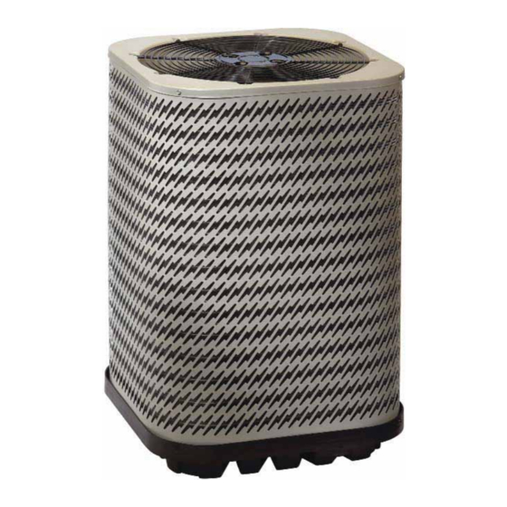
JS6BD SERIES
USER'S MANUAL / INSTALLATION INSTRUCTIONS
SPLIT SYSTEM AIR CONDITIONER
Please read this information thoroughly and become familiar with the capabilities and
use of your appliance before attempting to operate or maintain this unit. Keep this
literature where you have easy access to it in the future. If a problem occurs, check the
instructions and follow recommendations given. If these suggestions don't eliminate
your problem, call your servicing contractor.
The Installation Instructions are primarily intended to assist qualifi ed individuals
experienced in the proper installation of this appliance. Some local codes require licensed
installation/service personnel for this type of equipment. Please read all instructions
carefully before starting the installation.
IMPORTANT
DO NOT DESTROY. PLEASE READ CAREFULLY AND
KEEP IN A SAFE PLACE FOR FUTURE REFERENCE.
13 SEER
Advertisement
Table of Contents

Related Manuals for Nordyne JS6BD Series


Summary of Contents for Nordyne JS6BD Series
- Page 1 JS6BD SERIES 13 SEER USER’S MANUAL / INSTALLATION INSTRUCTIONS SPLIT SYSTEM AIR CONDITIONER IMPORTANT Please read this information thoroughly and become familiar with the capabilities and use of your appliance before attempting to operate or maintain this unit. Keep this literature where you have easy access to it in the future.
-
Page 2: Table Of Contents
USER INFORMATION WARRANTY INFORMATION Important Safety Information ........3 A warranty certifi cate with full details is included with the Operating Instructions ..........3 air conditioner. Carefully review these responsibilities with Cooling Operation .............3 your dealer or service company. The manufacturer will not Heating Operation .............3 be responsible for any costs found necessary to correct Operating the Air Conditioner for Automatic... -
Page 3: Important Safety Information
USER INFORMATION IMPORTANT SAFETY INFORMATION The continuous indoor blower operation can be obtained with the thermostat system mode set in any position, Safety markings are used frequently throughout this including OFF. manual to designate a degree or level of seriousness and should not be ignored. -
Page 4: Important Safety Information
INSTALLER INFORMATION IMPORTANT SAFETY INFORMATION CAUTION: INSTALLER: Please read all instructions before servicing this equipment. Pay attention to all safety warnings and This unit uses refrigerant R-410A. DO NOT use any other special notes highlighted in the manual. Safety any other refrigerant in this unit. Use of another markings are used frequently throughout this manual to refrigerant will damage the unit. -
Page 5: Air Conditioner Installation
• Survey the job site to determine the best location for General Information mounting the outdoor unit. See Table 3 (page 10) for The JS6BD series air conditioner is designed only for unit dimensions. outdoor rooftop or ground level installations. This unit has •... -
Page 6: Connecting Refrigerant Tubing Between The Indoor & Outdoor Unit
Connecting Refrigerant Tubing Between the Indoor ELECTRICAL WIRING & Outdoor Unit WARNING: CAUTION: To avoid risk of electrical shock, personal injury, This system uses R-410A refrigerant with POE or death, disconnect all electrical power to the unit oil. When servicing, cover or seal openings to before performing any maintenance or service. -
Page 7: Grounding
rating label and according to applicable local codes. Thermostat Connections See the unit rating plate for minimum circuit ampacity • Thermostat connections should be made in accordance and maximum overcurrent protection limits. with the instructions supplied with the thermostat and •... -
Page 8: Startup & Adjustments
If insuffi cient • Refrigerant charging charts are applicable only to air is detected, examine ductwork for leaks or matched assemblies of NORDYNE equipment and obstructions. listed airfl ows for the indoor coil. Refer to Figures 7 - 3. -
Page 9: Air Conditioner Maintenance
REPLACEMENT PARTS Proper maintenance is important to achieve optimum Replacement parts are available through all Nordyne distributors. performance from the air conditioner. The ability to properly Please have the complete model and serial number of the unit when ordering replacement parts. -
Page 10: Figures & Tables
FIGURES & TABLES DO NOT OBSTRUCT TOP OF UNIT Allow adequate clearance for airflow Model Number Height -H- Width -W- Depth -D- JS6BD- 27" 22 3/4" 22 3/4" 27" 22 3/4" 22 3/4" 35" 22 3/4" 22 3/4" 27" 30 3/4" 30 3/4"... - Page 11 Model No. JS6BD Volts-Cycles-Phase 208/230-60-1 Total Amps 11.6 18.1 23.5 24.3 30.7 Electrical Data Delay Fuse Max. Min. Circuit Ampacity 12.9 14.5 20.1 26.2 27.0 34.2 Area 13.3 15.3 15.3 17.8 Coil Rows-FPI 1-22 1-22 1-22 1-16 1-16 1-16 Tube Dia. Type Fan Motor Amps...
- Page 12 WIRING DIAGRAM Split System Air Conditioner (Outdoor Section) Single Phase NOTES: 1. Disconnec t all power before servicing. 1. Couper le courant avant de faire letretien. 2. For supply connections use copper conductors only. 2. Employez uniquement des conducteurs to “H” on 3.
- Page 13 Figure 5. JS6BD Wiring Diagram (3 Ton Units)
- Page 14 Split System Air Conditioner (Outdoor Section) Single Phase NOTES: 1. Couper le courant avant de faire letretien. 1. Disconnect all power before servicing. 2. Employez uniquement des conducteurs en cuivre. 2. For supply connections use copper conductors only. 3. Ne convient pas aux installations de plus de 150 volt a la terre. 3.
-
Page 15: Cooling Charging Charts
JS6BD CHARGING CHARTS - COOLING ONLY Application Notes on the Use of Charging Charts • This equipment’s cooling system contains refrigerant under high pressure. Always use safe and environmentally sound methods when handling refrigerant handling or servicing the unit. Review the factory literature and safety warnings prior to servicing. - Page 16 S6BD024 K TXV Charging Chart Remove refrigerant when above curve Add refrigerant when below curve Liquid Temperature ( ° F) Figure 7. Charging Chart for 2 Ton Units NOTE: Do not add or remove refrigerant if pressure reading is between the curves. S6BD030 TXV Charging Chart Remove refrigerant when above curve Add refrigerant when below curve...
- Page 17 S6BD036TXV Charging Chart Remove refrigerant when above curve Add refrigerant when below curve Liquid Temperature ( ° F) Figure 9. Charging Chart for 3 Ton Units NOTE: Do not add or remove refrigerant if pressure reading is between the curves. S6BD042 K TXV Charging Chart Remove refrigerant when above curve Add refrigerant when below curve...
- Page 18 S6BD048 K TXV Charging Chart Remove refrigerant when above curve Add refrigerant when below curve Liquid Temperature ( ° F) Figure 11. Charging Chart for 4 Ton Units NOTE: Do not add or remove refrigerant if pressure reading is between the curves. S6BD060K TXV Charging Chart Remove refrigerant when above curve Add refrigerant when below curve...
-
Page 20: Installation / Performance Checklist
INSTALLATION/PERFORMANCE CHECK LIST REFRIGERATION SYSTEM: INSTALLATION ADDRESS: Was unit given 24 hr warm up period for crankcase heaters? CITY ________________________ STATE ________________ Stage-1 Liquid Pressure (high side) ________________________ UNIT MODEL # ________________________________________ Stage-1 Suction Pressure (low side) ________________________ UNIT SERIAL # _______________________________________ Has the owner’s information been Unit Installed Minimum clearances per reviewed with the customer?