Table of Contents
Advertisement
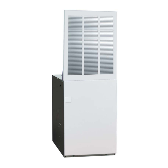
Downfl ow, Upfl ow Electric Furnaces
Owners Manual & Installation Instructions
E3 Series (Air Conditioner / Heat Pump Air Handler)
IMPORTANT
User, please read this information thoroughly and become familiar with the capabilities and
use of your appliance before attempting to operate or maintain this unit. Keep this literature
where you have easy access to it in the future. If a problem occurs, check the instructions and
follow recommendations given. If these suggestions don't eliminate your problem, call your
servicing contractor.
The Installation Instructions are primarily intended to assist qualifi ed individuals experienced
in the proper installation of this appliance. Some local codes require licensed installation/
service personnel for this type of equipment. Please read all instructions carefully before
starting the installation.
DO NOT DESTROY. PLEASE READ CAREFULLY AND
KEEP IN A SAFE PLACE FOR FUTURE REFERENCE.
Advertisement
Table of Contents

Related Manuals for Nordyne Air Conditioner / Heat Pump Air Handler


Summary of Contents for Nordyne Air Conditioner / Heat Pump Air Handler
- Page 1 Downfl ow, Upfl ow Electric Furnaces Owners Manual & Installation Instructions E3 Series (Air Conditioner / Heat Pump Air Handler) IMPORTANT User, please read this information thoroughly and become familiar with the capabilities and use of your appliance before attempting to operate or maintain this unit. Keep this literature where you have easy access to it in the future.
-
Page 2: Table Of Contents
TABLE OF CONTENTS USER INFORMATION IMPORTANT SAFETY INFORMATION .......3 UNIT MAINTENANCE ..........4 Furnace Filter ............4 OPERATING INSTRUCTIONS ........3 Coil Filter ..............4 Cooling Operation ...........3 Blower Compartment ..........4 Heating Operation ...........3 Operating the Blower Continuously ......3 TROUBLESHOOTING ..........4 Turning the Heater OFF ..........4 INSTALLER INFORMATION Standard Duct Connector Installation ....10 IMPORTANT SAFETY INFORMATION .......5... -
Page 3: Important Safety Information
USER INFORMATION IMPORTANT SAFETY INFORMATION Safety markings are used to designate a degree or level of seriousness and should not be ignored. WARNING WARNING: indicates a potentially hazardous situation that if not Do not use this furnace if any part has been under avoided, could result in personal injury or death. -
Page 4: Turning The Heater Off
USER INFORMATION renovated homes may require more frequent changing Turning the Heater OFF until the construction dust has minimized. Filter sizes Change the thermostat’s system mode to OFF and the fan shown in Table 6 (page 19) are available at most local mode to AUTO (See Figure 1). -
Page 5: Important Safety Information
INSTALLER INFORMATION IMPORTANT SAFETY INFORMATION INSTALLER: Please read all instructions before servicing Minimum Installation Clearances this equipment. Pay attention to all safety warnings and • Access for positioning and servicing the unit must be any other special notes highlighted in the manual. Safety considered when locating unit. -
Page 6: Circulating Air Requirements
fl ushed to it. This installation provides Standard for Installation of Air Conditioning Systems an access door for future installation of NORDYNE air (NFPA 90A), Standard for Installation of Residence Type conditioning or heat pump coils on top of the furnace. -
Page 7: Unconditioned Spaces
Unconditioned Spaces Frame All duct work passing through unconditioned space must be properly insulated to minimize duct losses and prevent Fasteners (4) condensation. Use insulation with an outer vapor barrier. Refer to local codes for insulation material requirements Top of Furnace Closed-Off Spaces Living space not served by, and closed off from the return air... -
Page 8: Furnace Installation
local building codes. If there is any question concerning the power supply, contact the local power company. 24 3/4” (628 mm) Verify the air delivery of the furnace is adequate to handle the static pressure drop of the coil, fi lter, and duct work. -
Page 9: Locating & Cutting Floor Openings
REAR WALL OF CLOSET OR ALCOVE REAR WALL OF CLOSET OR ALCOVE 1 3/4" MIN. 2 3/8" MIN. FLOOR CUT-OUT FLOOR CUT-OUT 14 1/2” X 14 1/2” 17 1/2” X 14” FOR DOWNFLOW FOR UPFLOW FURNACES WITH FURNACES WITH STD. DUCT STD. -
Page 10: Standard Duct Connector Installation
8. Bend both tabs on the mounting plate up 90° as shown Duct Connector in Figure 9. If Floor Cavity Type & Part Number “X” is: 9. Seal all connections with industrial grade sealing tape Standard Duct Screw Down or liquid sealant. 7/8”... -
Page 11: Round Duct Connector Installation
Alcove Installation Staples or sheet metal screws Duct connector tabs 1. Cut alcove rough openings to minimum dimensions shown in Figure 13 (page 12). 2. Attach frame assembly with four fasteners (provided or equivalent) into pre-punched holes on top of furnace. Narrow Duct Narrow... -
Page 12: Upfl Ow Furnaces
4. Secure front of unit with one or more fasteners at Upfl ow Furnaces mounting hole(s) provided or at tie-down tab. See The following steps describe installation instructions for Figure 21 (page 18). an overhead supply duct system with a return air system 5. -
Page 13: Through The Floor Return Air (Ducted)
ELECTRICAL WIRING Upflow Duct Connector WARNING: ELECTRICAL SHOCK, FIRE OR EXPLOSION Furnace HAZARD Failure to follow safety warnings exactly could result in serious injury or property damage. Improper servicing could result in dangerous Filter (one obtained operation, serious injury, death or property from furnace) Upflow Stand damage. -
Page 14: Connecting Supply Service Wires
• -010 model is factory-wired for single-branch supply 5. To install optional single-circuit kit: circuit only. a. Loosen lugs at supply side of circuit breakers. • -012 models are factory-wired for single-branch supply b. Remove cover from single-circuit kit (if supplied). circuit (single-circuit kit factory installed). -
Page 15: Changing Blower Speed
Plug/Receptacle Position Pin1 Pin2 Pin3 Pin4 Pin5 4 Speed Blower Med-LO Med-Hi High Control Box Blower Lead Yellow Blue Black Table 3. Furnace Blower Speed Data proper color-coded blower lead located inside the control Blower Installation box. The speed(s) set by the factory may be different from 1. -
Page 16: Start-Up & Adjustments
5-Wire Thermostat 4-Wire Thermostat Y RC RH G Wire Wire To A/C To A/C nuts nuts E3EB FURNACE Control Wiring E3EB FURNACE Control Wiring 2-Wire Thermostat Heat Pump Thermostat Unstripped Wire Wires nuts Wire nuts E3EB FURNACE Control Wiring E3EB FURNACE Control Wiring Figure 19. -
Page 17: Figures & Tables
FIGURES & TABLES Capacitor Motor Blower Strap Wheel Filter Filter Retainer Circuit Adapter Transformer (012 Models Only) Control Door Circuit Control Door (Right Side) Breaker (Left Side) Limit Blower Grounding Switch Relay Element Contactor 5 Ton Blower Motor Capacitor Blower Strap Wheel Figure 20. - Page 18 13 1/2” 17” VIEW VentilAire Knockout VentilAire Knockout (1 1/2” X 5”) (1 1/8” X 4 1/2”) T-Stat (Ø 5/8”) 20” 24 1/2” T-Stat RIGHT LEFT FRONT (Ø 5/8”) SIDE SIDE VIEW Electric Ø 1 1/8” 29” Ø 2” Ø 7/8” 2 1/4”...
-
Page 19: Table 6. Unit Specifi Cations
ELECTRICAL INFORMATION Furnace Models E3EB- 010H 012H 015H 017H 020H 023H 023H 5-Ton Rated Heating Output, Btuh (see note 1) 35,000 41,000 53,000 57,000 70,000 75,000 75,000 Watts (Total kw, Heating Elements & Blower) 10.4 12.0 15.4 16.6 20.4 22.0 22.0 Supply Voltage 240 Volts/60Hz/1-Phase... - Page 20 Model Maximum Minimum Low Voltage Supply Total Number Over-current Circuit Thermostat Circuit Amperes E3EB- Rating Ampacity Wire Size 010H Single 44.6 Single 51.2 2-Wire system 012H Dual "A" 27.1 maximum wire lengths: Dual "B" 24.2 24 Ga. = 55' 22 Ga. = 90' Single 65.4 20 Ga.
-
Page 21: Wiring Diagram
WIRING DIAGRAM Optional 4-Speed WARNING Blower Switch circuit breakers to the “off” Model: E3EB-010H position before servicing the furnace. NOTES: 1. Supply wire size must be in accordance to the applicable revision of the NEC and all other applicable codes. 2. - Page 22 WIRING DIAGRAM Optional 4-Speed WARNING Blower Switch circuit breakers to the “off” Models: E3EB-012H position before servicing the furnace. NOTES: 1. Supply wire size must be in accordance to the applicable revision of the NEC and all other applicable codes. 2.
- Page 23 WIRING DIAGRAM Optional 4-Speed WARNING Blower Switch circuit breakers to the “off” Models: E3EB-015H, 017H position before servicing the furnace. NOTES: 1. Supply wire size must be in accordance to the applicable revision of the NEC and all other applicable codes. 2.
- Page 24 WIRING DIAGRAM Optional 4-Speed WARNING Blower Switch circuit breakers to the “off” E3EB-020H, 023H, 023H-5 Ton; E2EB-015HBR position before servicing the furnace. NOTES: 1. Supply wire size must be in accordance to the applicable revision of the NEC and all other applicable codes.
-
Page 28: Installation Performance Checklist
INSTALLATION / PERFORMANCE CHECK LIST ATTENTION INSTALLERS: ELECTRICAL SYSTEM: Electrical connections tight? It is your responsibility to know this product better than your customer. This includes being able to install the product according to strict Line voltage polarity correct? safety guidelines and instructing the customer on how to operate and maintain the equipment for the life of the product.