Table of Contents
Advertisement
Quick Links
Advertisement
Table of Contents

Related Manuals for EverFocus EPTZ2700


Summary of Contents for EverFocus EPTZ2700
- Page 1 Speed Dome EPTZ2700/EPTZ2700I USER MANUAL Date: Oct. 2008...
-
Page 2: Table Of Contents
Feature ......................9 1.3.1. Profile of EPTZ2700/EPTZ2700I ............9 1.3.2. EPTZ2700/EPTZ2700I Base Board ............ 10 1.4. EPTZ2700/EPTZ2700I Quick Operation Guide (Work with EKB500) ..12 2. EPTZ2700/EPTZ2700I INSTALLATION ..........13 2.1. Packing List ....................13 2.2. Cable Needed .................... 14 2.3. - Page 3 3.2.1. EXPOSURE ..................33 3.2.2. FOCUS MODE ..................35 3.2.3. DIGITAL ZOOM ................... 35 3.2.4. WHITE BALANCE ................35 3.2.5. BACKLIGHT ..................36 3.2.6. DAY/NIGHT ..................36 3.2.7. COLOR ....................37 3.2.8. NEGATIVE ..................37 3.2.9. WIDE DYNAMIC RANGE ..............37 3.2.10 EXIT ....................
- Page 4 EXIT ....................57 3.7. SYSTEM ..................... 58 3.8. INFO ......................59 3.9. EXIT ......................60 4. EPTZ2700/2700I FUNCTION SETUP AND OPERATION ..... 61 4.1. Manual Control Mode ................61 4.2. Auto Pan Mode ..................61 4.3. Position Setting ..................62 4.4.
-
Page 5: Eptz2700/Eptz2700I Overview
1. EPTZ2700/EPTZ2700I OVERVIEW 1.1. Introduction EPTZ2700 series has 2 types, EPTZ2700 is outdoor type whereas EPTZ2700I is indoor type, using high sensitivity and high resolution CCD to display high quality image. The design of ICR (IR cut filter removable) can provide real color even under strong sunlight in day time. - Page 6 Furthermore, the micro control unit enables camera a nimble and exact movement from minimal 0.01°/sec to maximal 360°/sec. It can go to every preset position in 1 second. It also has other advantages such as: 192 preset positions are available. 16 cruise tours can be set, and each tour contains up to 16 positions.
-
Page 7: Specifications
1.2. Specifications Product Model EPTZ2700 (outdoor) EPTZ2700I (indoor) Pickup Device 1/4” CCD Video Format NTSC or PAL Scanning System NTSC: 525 TV lines, 60 fields/sec PAL: 625 TV lines, 50 fields/sec. Picture Elements 768 x 494 (NTSC) 752 x 582 (PAL) - Page 8 Horizontal Rotation Range 360° unlimited rotation Tilt Rotation Range 90° pendulum motion Auto Zoom Speed Control Control speed auto-adjusted according to zoom length changing Auto Pan, 2 points Can set freely scanning 1-255 grade available Auto Pan Speed 1-99 second available Dwell Time (2 points) Preset Positions 192 positions...
-
Page 9: Feature
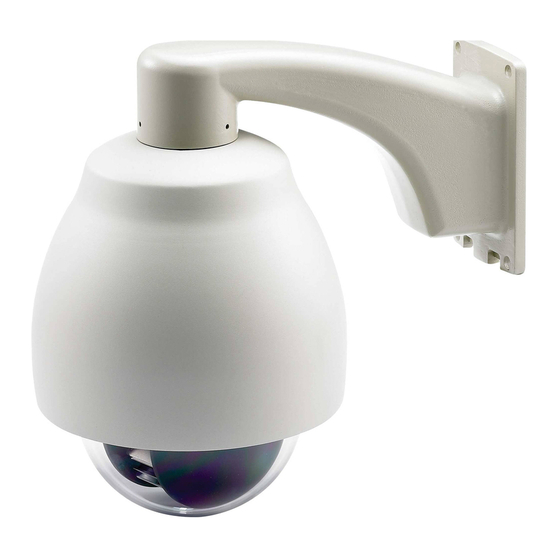
1.3. Feature 1.3.1. Profile of EPTZ2700/EPTZ2700I EPTZ2700 Wall Mount Bracket Top housing Outer housing Sun shield (optional) Camera main body Bubble Camera module EPTZ2700I Top housing Camera Outer housing main body Bubble Camera Module... -
Page 10: Eptz2700/Eptz2700I Base Board
1.3.2. EPTZ2700/EPTZ2700I Base Board The base board that is inside the top housing connects to power cable, video cable, control cable, alarm cable and fan. In order to connect to cables, the board needs to be taken off, and put back after finishing connecting to all cables. The connectors of cable names are marked on the board in white text. - Page 11 Pin # Function ALM_NO_B (Alarm Output Normal Open B) ALM_COM_B (Alarm Output Common B) ALM_NC_B (Alarm Output Normal Close B) ALM_NO_A (Alarm Output Normal Open A) ALM_COM_A (Alarm Output Common A) ALM_NC_A (Alarm Output Normal Close A) ALMIN1 (Alarm Input 1) GND (Ground) ALMIN2 (Alarm Input 2) ALMIN3 (Alarm Input 3)
-
Page 12: Eptz2700/Eptz2700I Quick Operation Guide (Work With Ekb500)
2. Connect a video cable from EPTZ2700/EPTZ2700I to a monitor. 3. Connect the power to the EPTZ2700/EPTZ2700I and a keyboard (EKB500). After the EPTZ2700/EPTZ2700I finishes the self-test mode, you can start to operate the EPTZ2700/EPTZ2700I via the keyboard. To operate the EPTZ2700/EPTZ2700I:... -
Page 13: Eptz2700/Eptz2700I Installation
2. EPTZ2700/EPTZ2700I INSTALLATION 2.1. Packing List There are 3 boxes that are camera main body with a camera module, top housing with a base board & pin connector and outer housing with bubble, plus one tool packet in the package. The detail accessories are listed below:... -
Page 14: Cable Needed
Note: The input AC voltage range of an adapter depends on different area. Please make sure the voltage range before installing. Video Cable A BNC cable is used for connecting an EPTZ2700/EPTZ2700I to a DVR or a monitor. An amplifier may be needed if the video cable is too long. RS485 Cable Yellow wire represents RS485+, orange wire represents RS485-. -
Page 15: Initial Setup
EPTZ2700/EPTZ2700I to enable a new value after changing. 2.3.1. Address Setting The address code of the EPTZ2700/EPTZ2700I should be set to correspond properly with a control device to control multiple dome cameras. The address codes are made up by the dipswitch on the camera main body. The 8 bits dipswitch indicates the binary coded of the address, and there are 256 addresses can be selected (0 ~ 255). - Page 16 1 2 3 4 5 6 7 8 1 2 3 4 5 6 7 8 Protocol/Baud rate/ Terminal resistance ID address...
- Page 17 Switch Address Switch Switch Switch Address Address Address Switch Switch Switch Switch Address Address Address Address Switch Switch Switch Switch Switch Address Address Address Address Address...
- Page 18 Switch Address Switch Switch Switch Address Address Address Switch Switch Switch Switch Address Address Address Address Switch Switch Switch Switch Switch Address Address Address Address Address...
-
Page 19: Communication Protocol Setting
Notice: Please make sure the power is off before setting, and restart the EPTZ2700/EPTZ2700I to enable a new value after changing. Set all of protocol switches to ON; the speed dome EPTZ2700/EPTZ2700I will enter a self-test mode. 2.3.3. Transmission Speed Setting (Baud Rate Setting) -
Page 20: Bracket And Speed Dome Installation
Service personnel should expect potential problems such as surface strength, surface material, falling objects, outer breaches, building vibration or other similar conditions. 2. Check for all necessary materials, and ensure if the selected installation location is suitable for the EPTZ2700/EPTZ2700I. Bracket Bracket base Top housing... -
Page 21: Eptz2700 Dome Camera Installation
2.4.2. EPTZ2700 Dome Camera Installation Note: Installation location that is a wall, a pole or a ceiling needs to support above five times the total weight of the camera assembly (about 16 kg) to avoid shaken images, and dropping. 1. Pull the hole of the base board to open it. Detach the power and RS485 wires first by using a screw driver. - Page 22 2. Apply the adhesive stripe at back of desiccant pack to the inner side of the top housing. There are totally 3 desiccant packs to be applied. 3. When all the desiccant packs are pasted and alarm cables are connected properly, put the base board back to its original place, you will need to pull open the switch in order to have the base board fitted to the top housing.
- Page 23 4. Connect the cable you detached from base board to the RS485 cable, Power cable and video cable you tread from the wall or ceiling. RS485 cable has to be connected via a terminal block. If you need to connect alarm cable, thread the alarm cable through the second hole.
- Page 24 6. Thread the cable through the bracket. 7. Screw the top housing to bracket by using a hexagon wrench.
- Page 25 8. Screw in 4 long screws to fix the bracket to bracket base. 9. Pull the hole of base board to open it again. Connect the power and RS485 wires back to power pin and RS485 pin. If you need to connect alarm, connect alarm cable to alarm pin.
- Page 26 a. Locate the hook first. Hook b. Clasp the rope to the hook firmly.
- Page 27 c. Done!
- Page 28 11. Hold and push the main body toward the bracket until it is firmly fixed to the bracket. To release it, press orange buttons at both sides of the body. 12. Twist the cover of main body to top housing clockwise until it is firmly fixed to top housing.
- Page 29 13. Turn on the power, and start to operate the EPTZ2700. Note: When turning on the power, EPTZ2700 will enter self-inspection mode, and carry out a self-testing program. After finishing self-inspection, you can start to operate the...
-
Page 30: Accessories
2.5. Accessories 2.5.1. EPTZ-CPMA: Ceiling Pendant Mount Adapter The ceiling pendant mount adapter is used for installing a speed dome on the ceiling indoors or outdoors. The extension poles are available for the pole mount. 2.5.2. EPTZ-PMA: Pole Mount Adapter The pole adapter is used for installing a wall mount bracket to a pole indoors or outdoors. -
Page 31: Eptz- Cma: Corner Mount Adapter
2.5.3. EPTZ- CMA: Corner Mount Adapter The corner mount are used for installing a wall mount bracket to a 270° corner of walls indoors or outdoors. -
Page 32: Eptz2700/Eptz2700I Camera Setup Menu
3. EPTZ2700/EPTZ2700I CAMERA SETUP MENU In this section, setup and operation guide of EPTZ2700/EPTZ2700I will be introduced. There are 8 items of the setting menu. 3.1. Structure of the Setup Menu Press MENU to enter camera setup menu. Turn the Joystick up/down to change subentries, and right/left to change the setting. If there is an arrow at the end of selection, it means that selection has a sub-menu, please press Enter key of keyboard to enter sub-menu. -
Page 33: Video Settings
3.2. VIDEO SETTINGS In main menu, turn joystick Up / Down to select VIDEO SETTINGS. Turn joystick Left / Right to enter VIDEO SETTINGS sub-menu (see diagram 3.2). EXPOSURE VIDEO SETTINGS <┘ POSITIONS FOCUS MODE ONE PUSH OSD/AREAS DIGITAL ZOOM AUTO MODES WHITE BALANCE AUTO... - Page 34 There are 4 options in Exposure: EL. SHUTTER, SLOW SHUTTER, IRIS MODE, and AE SPEED. EL.SHUTTER: Select electronic shutter mode from the options of the menu. There are AUTO, A.FLK , 1/50, 1/125 , 1/250 , 1/1000 , 1/2000 and 1/10000. AUTO: Auto electrical shutter A.FLK: Anti-Flicker.
-
Page 35: Focus Mode
NOTE: If EL. SHUTTER is selected, SLOW SHUTTER will be disabled. IRIS MODE: MANUAL: Manual Iris. AUTO: Auto Iris. EXIT: Select Exit to save settings and exit from current page. 3.2.2. FOCUS MODE In Focus mode, we define focus type from ONE PUSH, AUTO and Manual. ONE PUSH: Enable the one push trigger focus mode. -
Page 36: Backlight
AUTO: this mode computed the white balance value output using color information from the entire screen. It outputs the proper value using the color temperature radiating from a black subject based on a range of values. INDOOR: Camera’s white balance is fixed to indoor 3200 K. OUTDOOR: Camera’s white balance is fixed to outdoor 5100 K. -
Page 37: Color
3.2.7. COLOR In Color, we define color of the image. Select from ON and OFF. ON: Color image OFF: B/W image 3.2.8. NEGATIVE In Negative mode, it will switch ON/OFF the negative art image output. Select from ON and OFF. 3.2.9. -
Page 38: Positions
3.3. POSITIONS In main menu, turn joystick Up or Down to select POSITION option. Press Enter key or turn joystick Left / Right to enter POSITION sub-menu (See diagram 3.4). VIDEO SETTINGS POSITIONS OSD/AREAS SET POSITIONS <┘ AUTO MODES EXIT ALARM SYSTEM INFO... - Page 39 PRESET NO. 1 POSITION <┘ SPEED DWELL TIME (S) MOVE TO POSITION FOCUS MODE MANUAL IRIS+: SAVE AND RETURN WHITE BALANCE AUTO TITLE DEFAULT RETURN (diagram 3.6) POSITION: Select from SET and CLEAR. SET: Select SET and press Enter key of keyboard, you will be entered to a sub-menu. Turn the joystick to your desired position.
- Page 40 SPEED: Select the speed for the preset position. The value is from 1 to 255 and 255 is the highest speed. DWELL TIME (S): Select the dwell time (in second) for the preset position from 1 to 99. FOCUS MODE: Select focus mode for the preset position from MANUAL, ONE PUSH and AUTO.
-
Page 41: Osd/Areas
3.4. OSD/AREAS In main menu, turn joystick Up or Down to select OSD/AREAS. Turn joystick Left or Right to enter OSD/AREAS sub-menu (see diagram 3.8) VIDEO SETTINGS POSITIONS CAM. TITLE EPTZ2700__ OSD/AREAS AREAS <┘ AUTO MODES DIRECTIONS <┘ ALARM DISPLAY <┘... - Page 42 In zone menu, you can set a zone and name it, when the speed dome turns to the zone you set, it will display zone name on the screen (only if “OSD/AREAS->Display -> Zone” is set as “YES”). Turn the joystick to Up/Down to select the character. Turn the joystick Left or Right to select the character position.
-
Page 43: Directions
Turn joystick Right/Left to highlight the zone you have set and turn the joystick Up/Down to select another zone number. If you wish to clear the zone you have set, go to “CLR” and press Enter key. 3.4.3. DIRECTIONS Press Enter key of keyboard or turn joystick Left/Right to enter DIRECTIONS sub-menu (see diagram 3.12) DIRECTIONS NORTH CAM. - Page 44 3. Press IRIS+ key of keyboard to save and return. DIRECTIONS NORTH SET NORTH <┘ DEFAULT NORTH [PUSH ENT] RETURN (diagram 3.14) 4. Go to “DEFAULT NORTH” and press Enter key to set the north position as default north position. 5.
-
Page 45: Display
3.4.4. DISPLAY Press Enter key of keyboard or turn joystick Left/Right to enter DISPLAY sub-menu (see diagram 3.15) SHOW OSD CAMERA TITLE CAM. TITLE EPTZ2700__ DIRECTIONS AREAS <┘ ZONES DIRECTIONS <┘ PRESET TITLE DISPLAY <┘ ZOOM EXIT MOTION CAMERA STATUS RETURN (diagram 3.15) 1. -
Page 46: Exit
4. ZONES YES: show zones NO: do not show zones 5. PRESET TITLE YES: show preset title NO: do not show preset title 6. ZOOM YES: show zoom multiple when zoom in or zoom out. NO: do not show zoom multiple. 7. -
Page 47: Auto Modes
3.5. AUTO MODES In main menu, turn joystick Up/Down to select AUTO MODES. Turn joystick Left/Right to enter AUTO MODES sub-menu (See diagram 3.16) AUTOPAN VIDEO SETTINGS <┘ POSITIONS PRESET TOURS <┘ OSD/AREAS PATTERN <┘ AUTO MODES AUTO RESUME ALARM RESUME TO POS.1(H) SYSTEM... - Page 48 auto-pan. OFF: disable endless mode. The speed dome will perform auto-pan between position left and position right. b. SPEED Select speed from 1~255 and 255 is the highest speed. c. DWELL TIME L (S) Select dwell time of the left position from 1~99 seconds. d.
-
Page 49: Preset Tours
f. SET RIGHT POS. Press Enter key or turn the joystick Left/Right to enter SET RIGHT POS. menu. Turn the joystick to the position where you wish to set RIGHT position. Press IRIS+ key of keyboard to save setting and return to previous menu. (see diagram 3.19) AUTOPAN ENDLESS MODE SPEED... - Page 50 TOUR NO. 1 AUTOPAN <┘ DWELL SPEED PRESET TOURS <┘ PRE1 DEFAULT DEFAULT <┘ PATTERN <┘ PRE2 DEFAULT DEFAULT <┘ AUTO RESUME PRE3 DEFAULT DEFAULT <┘ RESUME TO POS.1(H) PRE4 DEFAULT DEFAULT <┘ POWER UP FUNC PREV MODE PRE5 DEFAULT DEFAULT <┘...
-
Page 51: Pattern
3.5.3. PATTERN Press Enter key of keyboard to enter PATTERN sub-menu (see diagram 3.21) AUTOPAN PATTERN SETUP <┘ PRESET TOURS PATTERN DURATION ACTION <┘ PATTERN <┘ PAT1 PLAY AUTO RESUME <┘ PAT2 PLAY RESUME TO POS.1(H) <┘ POWER UP FUNC PREV MODE PAT3 PLAY... -
Page 52: Auto Resume
e. When you return to PATTERN SETUP menu, turn the joystick Left/Right to PLAY. Press Enter key of keyboard. The camera starts to run the pattern tour you set. The camera keeps playing the pattern until you press IRIS- to cancel playing and it will return to PATTERN SETUP menu. -
Page 53: Power Up Func
3.5.6. POWER UP FUNC Turn the joystick Left or Right to select the mode to return to when power failure occurs. It is selectable from PREV MODE, POS.1 (H), TOUR1, PAT.1, AUTOPAN and OFF 3.5.7. AUTO FLIP Select ON to enable Auto Flip function or select OFF to disable Auto Flip. 3.5.8. - Page 54 number from 1 ~4. Type: Select Normal Close (NC), Normal Open (NO), NIGHT NC, NIGHT NO, or OFF for alarm type. NC: Enable a normal close alarm input. NO: Enable a normal open alarm input. NIGHT NC: Set camera at night mode with normal close alarm input. When there is event triggered, the camera will be changed to day mode.
- Page 55 joystick Left/Right to select on Pattern and press Enter key to select pattern number. Turn joystick Left/Right to make selection. It is selectable from1~4. Press Enter key again to confirm selection. TOUR: When the alarm is triggered, speed dome will run the tour. Turn the joystick Left or Right to select on Tour and press Enter key to select tour number.
-
Page 56: Alarm Outputs
3.6.2. ALARM OUTPUTS Press Enter key of keyboard to enter ALARM OUTPUTS sub-menu. (see diagram 3.26) ALARM OUTPUT TRIGGER ALARM INPUTS <┘ ALARM OUTPUTS <┘ OUTPUT NO EXIT INPUT1 INPUT2 INPUT3 INPUT4 SYSTEM ERROR NO REMOTE RETURN (diagram 3.26) a. OUTPUT NUM: Select Output number from 1~2. b. -
Page 57: Exit
Select NO to disable this function. i. RETURN: RETURN to the previous menu. 3.6.3. EXIT Exit from the current menu. -
Page 58: System
3.7. SYSTEM In main menu, turn joystick Up/Down to select SYSTEM. Turn joystick Left/Right to enter SYSTEM sub-menu (see diagram 3.27) VIDEO SETTINGS AUTO INIT POSITIONS LANGUAGE ENGLISH PASSWORD OSD/AREAS <┘ AUTO MODES LOAD DEFAULT [PUSH ENT] ALARM RESTART [PUSH ENT] SYSTEM EXIT INFO... -
Page 59: Info
PASSWORD ACTIVE: Select YES to activate password mode. Select NO to disable password mode. ENTER PASSWORD: Enter the password VERIFY PASSWORD: Enter the password again to confirm your input. Press IRIS+ key to save and return to previous menu. Press IRIS- key to cancel. d. -
Page 60: Exit
d. RS-485-ID: shows RS-485 ID of this speed dome e. PRESET-CNT: Preset counter. This counter counts the preset movement, and 1 is counted when the speed dome runs to preset position. f. X-CONT: X-axis counter. This counter counts the x axis movement, and 1 is counted when the speed dome pans 360°. -
Page 61: Eptz2700/2700I Function Setup And Operation
(1~239). Press Enter to start auto pan. In order to set the two points, press Set + A.Pan, and then enter the dwell time (1~127 seconds) of each point. EPTZ2700 begins to pan from point A to point B clockwise. -
Page 62: Position Setting
4.3. Position Setting Focus on a preset position: Press the number key, and then press Position to focus on the number of preset position; or you can press Position, then enter the preset position number, and then press Enter to focus on the number of preset position. -
Page 63: Tour Mode
setting dwell time of A pos or B pos. 99 => Auto scan (360 degree) Default speed is 32. It can be changed by EVF Keyboard (Shift + A.Pan setting speed). We can even set camera’s ICR Day/Night function with RS-485 command via keyboard. -
Page 64: Alarm Link To A Position/Tour
Tour, and input tour number 0. 4.5. Alarm Link to a Position/Tour EPTZ2700/EPTZ2700I have 4 alarm inputs that can be set to link to a position or a tour when an alarm is triggered. Set an alarm link: Press F1 to set an alarm link. -
Page 65: Other Operations
Note 2: After powering on the speed dome, it will detect alarm status automatically. 4.6. Other Operations The EPTZ2700/EPTZ2700I can work with a DVR that has PTZ control functions, and a matching protocol. The available control functions depend on different DVRs. - Page 66 Fax: 631-436-5027 TEL : +81-43-212-8188 FAX : +81-43-297-0081 www.everfocus.com www.everfocus.com Your EverFocus product is designed and Ihr EverFocus Produkt wurde entwickelt und manufactured with high quality materials and hergestellt mit qualitativ hochwertigen Materialien components which can be recycled and reused.